KI6ZHD
dranch at trinityos.com
06/09/24.0
Index:
Introduction:
Learning about the Hardware:
Initial OS setup:
Initial OS Security Hardening:
Initial OS Tuning:
Initial OS Management and Reporting:
System Cooling, Build Toolchain for Application Compiling:
Building up the AX.25 system:
Building up the Sound card system, PTT, and Software AX.25 TNC:
Connecting your Radio to the System:
Configuring the AX25 system and Linpac for Classic Packet Support:
Connect to an existing Wifi AP *or* have your RPi act as a Wifi AP to provide connectivity to other devices:
Raspberry Pi tricks for hardware monitoring, manage the onboard LEDs, using Bluetooth connectivity:
Accurate time and Location - Using Adding GPS location and GPS-based NTP time support:
Final things to review: Check your bootlogs:
Backing up your work - file and imaged-SD card based backups:
So you've probably been working on your Rasberry Pi this whole time just to get to this section
to do AX.25 packet radio. Right? If not and you're following this guide just to create secure,
reliable Raspberry Pi, then go ahead and skip a bunch of these sections!
If you are here for AX.25, read on!
So what are the Linux AX.25 packages and why do you really need them? If you plan on running AX.
25 packet radio on your Linux-based Raspberry Pi machine, you need these three core packages to
configure, enable, and link the complete AX.25 stack to packet enable your radio programs.
Here is a rough index of the required steps:
The first question many people ask me is "Why use the VE7FET AX.25 packages and not either the packages available from the OS repos or build the official AX.25 packages"? My reasoning is fully documented in my older AX.25 document for Centos Linux here:
Ultimately, the Official AX.25 repo is still out of date, is missing various critical fixes, etc. It's this repo that the stock Raspberry Pi OS / Debian packages are built from and as such.. Raspberry Pi OS's versions don't work well or outright crash all the time. The official AX.25 sources been getting some attention of the last few quarters but unless they make an official release, the Raspberry Pi OS / Debian packages will never get the fixes and thus continue to be broken. So.. we need to us better sources and compile them ourselves.
Page Views since 05/11/21:
0. Intro to setting up a Raspberry Pi and understanding it's quirks
Welcome to the world of the Raspberry Pi, Amateur Radio, and all the possibilities.  No doubt
there is an overwhelming amount of options and many people new to the Raspberry Pi, Linux, etc.
will get confused where to start.  This document hopes to provide some guidance here with a
specific application in mind (see the intro at the beginning of this document of it's goals).

Before you get started, a few thoughts:

   - SD cards: Only use quality, name brand SD cards supporting Class-10 speeds in your Pi.
     The use of quality cards will save you from countless amount lost time, anger of "stability
     issues with Raspberry Pis" and the overall setup will last a LOT longer (but it won't last
     forever without backups).  Also note that while a Class-4 speed card will work, the amount of
     slowness you'll experience is crazy and isn't worth it.  Only used a Class-10 or faster
     class card!

   - SD card size: As of Raspberry Pi OS Bookworm, even the 32bit Lite version is very tight
     on a 4GB card.  With a fully patched system, with the recommended tools and services running
     and an application or two installed, I'm at 73% full on the main / partition.  As such,
     I can only recommend an 8GB or larger card for Bookworm Lite or either GUI versions AT MINIMUM.

   - Power Supply: Only use a quality USB power supply and not just some old cellphone charger
     you had laying around the house.  The official Rpi power supply shipped with a 5.1volt (not 5.0v)
     @ 2.5Amp supply with a thick, short and quality made USB cable for many reasons. The new Rpiv4
     supply ships with a 3.0 amp supply and the Rpi5 ships with a 5.0A supply.  The use of random USB
     power bricks and cables will not work in your favor.. especially when the Rpi is under load.
     If you want to run your Raspberry Pi from a 12v battery, I've had good luck with these inexpensive
     UBEC DC to DC power bridges:
   - Operating System: Install the Raspberry Pi version of the Linux operating system on it ::
     This means NEWEST Raspberry Pi OS (was called "Raspbian" before) version to be specific

       - This specific document focuses and RECOMMENDS the use of the Raspberry Pi OS "Bookworm" aka Debiam 12
         release that came out on October 10, 2023.  That said, it also includes explicit support for previous OS
         releases like Bullseye aka Debian 11 released November 2021 but also covers unit points for say Buster,
         Stretch, Jessie, and even the Wheezy releases for some items.

       - I *highly* recommend you run the newest version of the Raspberry Pi OS available to get the best
         possible support, security fixes, etc.

         All older OS versions such as "Bullseye", "Buster", "Stretch", "Jessie", "Wheezy", etc. are either being
         phased out of getting any updates or have already stopped receiving any security patches from the Raspberry
         Pi Foundation or the Debian community.  In general, the previous OS release should continue to receive new
         kernel updates from the Rpi foundation for a few more months when a new release comes out.  Other OS package
         updates for non-core OS packages will also from the Debian community side for some quarters but without
         updated kernels, that doesn't mean your Rpi is secure.

       - New things in various Raspberry Pi OS releases:

            - Bookworm / Debian 12:
              ---------------------
                - Released October 10, 2023
                - Bookworm is the minimum OS version to Support the Raspberry Pi 5 hardware
                - Transition from X11 to Wayland window compositor by default
                  - It is reported that ONLY the Raspberry Pi 5, 4, CM4 and Pi 400 models will run Wayland for now
                    but it's possible a future Raspberry Pi OS Bookworm release might make the change to all SBC versions
                  - GTK and Qt, are now Wayland-compliant but other GUI tools using other UI interfaces that make legacy
                    X11 calls will automatically activate the new XWayland layer
                - Move from Mutter to Wayfire GUI compositor as part of the Wayland transition
                - Move from LXDE window manager to the new “wayfire panel" (wf-panel-pi)
                  - All existing lxpanel plugins were ported to the new Wayfire panel
                - OpenGL and Vulkan are both supported on Bookworm
                - Networking now defaults to use the previously optional NetworkManager subsystem; this all replaces the
                  quirky solution using dhcpcd for everything
                - Moved to Pipewire sound system from PulseAudio (lower latency, improved Bluetooth support)
                - Camera app raspistill will be entirely replaced by libcamera
                - new GUI power plugin shows power issues, throttling events, etc
                - RealVNC is currently not supported due to being incompatible with Wayland but this is evidently being
                  worked on.  Two workarounds are available:
                     1. Revert the default display system from Wayland back to the classic Xfree / Xwindows server
                     2. Use the TigerVNC client instead of the RealVNC client (still allows for authentication)
                     3. Disable encryption on RealVNC but continue to use RealVNC client (there is a potential security risk here)
                        https://forums.raspberrypi.com/viewtopic.php?t=357582
                        https://help.realvnc.com/hc/en-us/articles/14110635000221-Raspberry-Pi-5-Bookworm-and-RealVNC-Connect#statement-0-0

                - Python3 modules installed via pip require a new virtualized sandbox method to function
                  or always use a dangerous sounding command line option
                - Other notable differences:
                     Raspberry Pi OS overview: https://www.raspberrypi.com/news/bookworm-the-new-version-of-raspberry-pi-os/
                     Debian overview:          https://www.debian.org/releases/bookworm/amd64/release-notes/ch-information.en.html


            - Bullseye / Debian 11:
              ---------------------
                - Released April 4, 2022
                - Display drier for GUI interface now using Linux KMS
                - The LXDE desktop was upgraded from GTK+2 to GTK+3
                - Dynamic window manager selection based on Rpi hardware
                    >2GB RAM: Mutter
                    <2GB RAM: OpenBox
                - All Rpi4/CM4 with the "C" revision SOC and the "tri" chip power rail now run each core at 1.8Ghz
                  vs.  the previous 1.5Ghz
                - New GUI notification system including patches, low voltage, etc
                - GUI tool for OS patching now included
                - Chromium web browser now runs hardware acceleration by default
                - The OS is now using libcamera library instead of previous Broadcom proprietary binary blob
                    - This is evidently a rather disruptive update and all previous commands, tools break
                - The OS has a bit more memory overhead compared to older releases like Buster and earilier
                - This release doesn't add any new hardware releases


            - Buster / Debian 10:
              -------------------
                - Released on 7/21/19
                - LXDE using GTK+2
                - Minimum OS version to Support the Raspberry Pi 4, CM4, 400 hardware and later the Zero 2W hardware


            - Stretch / Debian 9:
              -------------------
                - Released on 8/6/2017
                - Minimum OS version to support the 3+ hardware

            - Jessie / Debian 8:
              -------------------
                - Released on 8/6/2017
                - Minimum OS version to support the Rpi 3 hardware and later the Rpi Zero W hardware

            - Wheezy / Debian 7:
              -------------------
                - Released on 09/27/2013
                - Minimum OS version to support the Rpi1 hardware and later Rpi2 hardware


       - Code Bloat: It's also worth mentioning that older OS releases WILL perform better on older Raspberry Pi
         hardware versions but without bug fixes and security updates.  Unfortunately, it's just not a good idea
         to run old OS versions unless you can ensure your Raspberry PI isn't connected to any networks like the
         Internet, etc.

       - Pre-created SD cards: If you you're starting out with a pre-created microSD card image which was included
         say in a Raspberry Pi kit and the /etc/os-release file doesn't show Debian 12 or 11, please consider just
         re-imaging or replacing the image to have the newest Raspberry Pi OS version available.  Doing this imaging
         is easy to do as long as you have a micro-SD card reader on an already functioning Windows, Linux,
         or Mac machine, follow these instructions:

            https://www.raspberrypi.org/documentation/installation/installing-images/


       - Understanding the different versions of Raspberry Pi OS

          - "Desktop with Recommended Software" vs "Desktop" vs "Lite":

                 - The "Raspberry Pi OS with desktop and recommended software" or "full" version of Raspberry Pi OS
                   includes the full GUI and a full load of additional packages.  If you want a GUI with a desktop
                   and lots of example programs to use, this "full" version is what you want.  It should be noted
                   that any GUI version will consume a LOT more RAM and CPU cycles that the non-GUI "Lite" version.

                 - The "Raspberry Pi OS with desktop" or "standard" version of Raspberry Pi OS includes a complete GUI
                   interface but does not include a lot of additional packages that I personally find as pretty useless
                   for amateur radio needs.  If you want to run GUI programs via say VNC and what not, THIS IS THE VERSION
                   YOU'LL PROBABLY WANT.  It should be noted that any GUI version will consume a significant more RAM and CPU
                   cycles that the non-GUI "Lite" version.

                 - *RECOMMENDED* : The "Raspberry Pi OS Lite" or "Lite" version of Raspberry Pi OS is the much smaller
                   and lighter version.  There isn't any offer any GUI support included though it can be added later.
                   This version is best used for headless operations say running as a packet radio node, etc. and is
                   what I personally use to maximize available RAM, etc.


          - 32bit vs. 64bit:  Raspberry Pi OS Full and Lite versions were traditionally offered as 32bit (ARMHF) *only*
                              which is generally all that's needed on these Rpi boards with low memory capacity (512MB and
                              later 1GB).  Starting with the Rpi3, the ARM processor was upgraded to support 64bit (ARM64)
                              instructions.  The primary benefit/need for 64bit gives the computer the ability to address
                              more than 4GB of RAM (such as the 8GB version of the Rpi4 and RPi5) but using 64bit can also
                              offer some performance benefits for specific workloads. The downside of going to a 64bit OS
                              is that it actually increases the system's average RAM utilization compared to 32bit for the
                              same workload.

                              On the newest Raspberry Pi 5/4/400/CM4 models, you can get versions with up to 8GB of
                              RAM to help offset this increased memory usage.  On 02/03/2022, the Raspberry PI Foundation
                              released the 64bit version of Bullseye "production grade" from being in BETA for many
                              quarters.  Why did it take so long?  See the comments here for more details:

                                 https://www.raspberrypi.com/news/raspberry-pi-os-debian-bullseye/

                              From some of those comments in that thread, it's clear that the 32bit CPU era is ending
                              as many programs are dropping 32bit built binaries and are ONLY offering 64bit versions:

                                 - LibreOffice 7.0 and newer will only be 64bit for the versions released by
                                   The Document Foundation
                                 - Many published Docker container images are only 64bit now
                                 - Other programs are now only 64bit: Elastic Search, MongoDB, etc

                              I generally would now recommend to use the 64bit OS versions if your hardware supports it.
                              Why?  That code is getting a lot more use and testing by users so it should be more reliable
                              but there will be a performance penalty on slower generations of hardware.

                              Anyway, here are some download URLs for the 64bit OS images:

                                 Smaller 64bit GUI version:   https://downloads.raspberrypi.org/raspios_arm64/images/
                                 Lite 64bit CLI-only version: https://downloads.raspberrypi.org/raspios_lite_arm64/images/


               Benchmarks with Raspberry Pi OS 64bit from May 2020:
               https://www.tomshardware.com/news/raspberry-pi-4-8gb-tested

               Some performance benchmarks from Jan 2020:
               https://medium.com/@matteocroce/why-you-should-run-a-64-bit-os-on-your-raspberry-pi4-bd5290d48947


        - Why run the Raspberry Pi OS vs other alternative OSes?

          Yes, there are many other alternative Linux OSes that run on the Raspberry Pi but *none* of them
          match the performance focus, support and bug fix cadence of the Raspberry Pi OS for Raspberry Pi hardware.
          Maybe some distros claim focus on the Raspberry Pi like DietPi and they might come to a distant second
          but it's not going to be to the same level as any OS from the Raspberry Pi Foundation.

          You also might find other pre-made Rpi images from various people for say the DVMega project or other
          things and I say you should give them a try.  Going with the pre-made image approach makes it easy to
          try new software stuff by just swapping out different micro-SD flash cards.  Do be wary though...

           - What is the providence of these images?  Do you trust the creator of this image?  Why do you trust them?
               Are these pre-made images using the official Raspberry Pi OS to benefit from the patches and security?
           - Were those images built and and secured properly?
           - Are these images being kept up to date?

         It's hard to answer YES to all those questions but the decision is yours.


          A quick list of alternative distros (you can find many more here: https://elinux.org/RPi_Distributions ):
          ---------------------------------------------------------------------------------------------------------
          (Listed in Alphabetical order):

          Arch Linux : More of a advanced Linux distributions for experienced Linux users

          Debian : This is the basis for Raspberry Pi OS but without many of the useful tools like
                   rasp-config, vcgencmd, and the customized Linux kernel for the Broadcom SOC

          DietPi : This is a Debian based distro focused on the Raspberry Pi but focuses on dramaically reducing
                   it's running RAM utilization and storage requirements

          Devuan : This is debian but not using the SystemD system

          Fedora : A general desktop focused distro

          FreeBSD : FreeBSD for the Raspberry Pi OS

          Gentoo Linux : More of ab advanced Linux distributions for experienced Linux users

          Kali Linux : An advanced security toolkit focused Linux distribution

          OpenSuse: A general desktop focused distro

          RaspBSD : FreeBSD for the Raspberry Pi OS

          Risc OS: A non-Linux kernel based distro

          SARPi / Slackware: A general desktop focused distro

          Ubuntu : A general desktop focused distro

          Windows IOT : A stripped down base Windows kernel for IOT functions

          [There are many others as well]


        There are also other purpose built "appliance" images but I wouldn't call them Linux distributions:
        ---------------------------------------------------------------------------------------------------
           - Amateur Radio RoIP: HamVoIP, Allstar, etc
           - Kodi media player needs: OSMC, OpenElec
           - Retro gaming needs: Batocera, BMC64, Lakka, RetroPie
           - Home automation needs: Domoticz


        Pre-built HAM images:
        ---------------------
        - There are some good alternative / pre-configured images that you might consider.  Many of them are
          not properly maintained IMHO and most already quite old.  The benefit of using one of these images
          is that much of the work to get all the packages installed and configured is already done for you.
          Some even have tools to help with the configuration.


           .. but a word of Warning on pre-built HAM images:
           -------------------------------------------------
           I once downloaded a RPI packet radio image from a trustworthy HAM and yet noticed some strange log
           entries and behavior.  I then did some security investigation and it turns out his Rpi been
           compromised before he imaged it and then published that image on the Internet!  When I proved this
           compromise to the image owner, he was shocked and immediately took it down.  It was not intended by
           him to published a hacked image but it happened regardless.  There is no free lunch when it comes
           to easy to install vs.  good security here but I bet 95% of the Rpi images out there are good.
           Just watch for that last 5%.


   - Security and Patching:
      - If your Rpi setup is going to be directly connected to the Internet, PLEASE keep the OS patched
        every week (ideally every day).  Most Raspberry Pi OS and even older Raspbian OS releases will follow
        the official Debian LTS patching modeli per Peter Green's post on 11/8/21 @ 8:54pm at
        https://www.raspberrypi.com/news/raspberry-pi-os-debian-bullseye/ .  Debian's LTS schedule is here:

           https://wiki.debian.org/LTS

        With that understood, the Raspberry Pi kernel -=* does NOT follow *=- that cadence for it's kernels
        and tools.  Per the above "raspberry-pi-os-debian-bullseye" URL comments, it's understood that when a
        new Raspberry Pi OS version is released such as Bookworm, all previous OS's like Bullseye will see an
        immeadiate and significant slowdown on getting any new updates and will soon stop seeing ANY kernel
        updates.  This means that to receive the most up to date security and bug fixes, you MUST always run
        the newest OS release from the Raspberry Pi Foundation as soon as it's released.


      - Other recommended security recommendations:

        - Legacy versions only: Disable the "pi" account and install an IPTABLES firewall on it.  Modern
          Rpi OSes have already dropped the creation of the "pi" user

        - Don't expose say SSH (port 22) and other services directly to the Internet if you can help it.
          If you do need to offer external SSH, at least change the answering port from say TCP/22 to
          something like TCP/5353.  It's been said that you should NOT use any port number that includes
          "22" as the common portscaners will look for that.

         - Another good idea is to ONLY use SSH keys (ideally with passphrases) and disable all password
           authentication if you can compared to just using accounts with passwords.  These few steps alone
           greatly reduces your security attack surface.  This is covered in a different chapter in this
           document.


  - Safe Shutdown:
    I recommend to connect a shutdown button so it's easy to turn off your Raspberry Pi safely.  The Raspberry
    Pi 5 is the very version of Rpi HW to include this critical function by default.  It's very important that
    you *MUST NOT* just unplug the Raspberry Pi's power cord when you want to turn it off.  If you do this,
    you run the risk of eventually corrupting the OS on the SD card.  Adding a shutdown button on older Pis
    is very easy and only takes two wires, a resistor, a momentary button, and setting up a simple script).
    This is all covered later in this doc.


I could go on and on here in the intro but I won't.  Instead, that's what the following chapters in
this document is for!  Good luck with the project and if you're new to Linux.. take your time.  There
is lots to learn and it can be intimidating at times.  Do as much research on Google before becoming too
frustrated.  At that point, feel free to email me or join some of the various help lists like the
excellent RaspberryPi-4-HamRadio@groups.io list.   There are lots of helpful and patient Linux
HAMs there that are ready to help.

Anyway.. let's get down to it!
1. Differences in Raspberry Pi hardware versions, downloading the SD image and installing it
I want to highlight the key differences between the Rpi 5, 4, CM4, 400, 3+, CM3, 3, 2, 1, Zero W2,
and Zero W, and Zero versions of these boards.  I generally recommend people to either start with the
newest boards available due to many of it's substantial improvements for reasonable prices UNLESS they
have specific requirements (lower cost, lower power consumption, smaller formfactor, etc)
   +--------------------------------------------------------------------------------------------+
   | 09/30/23 - Thoughts on Rpi Limited Availability (updated from 09/17/22)                    |
   |                                                                                            |
   |    Buying a Raspberry Pi board is generally much easier to buy these days but few places   |
   |    can keep stock for long and it's only on select models.  You can try to monitor the Rpi |
   |    Locator website at:                                                                     |
   |                                                                                            |
   |       https://rpilocator.com/                                                              |
   |                                                                                            |
   |   to see if any stock becomes available but any available supply goes very quickly.        |
   |   Many groups have had to move on and use alternative hardware for their needs.  The       |
   |   following sites give some good overview of some of these hardware platforms but          |
   |   please note that they won't run Raspberry Pi OS and may or WILL have various hardware    |
   |   compatibility issues with generalized Linux:                                             |
   |                                                                                            |
   |      website:    https://kc7mm.com/wiki/doku.php?id=linux:devices:raspberrypi:alternatives |
   |      discussion: https://groups.io/g/linuxham/topic/91519954#49066                         |
   |      discussion: http://lists.hamvoip.org/pipermail/arm-allstar/2022-September/018155.html |
   |                                                                                            |
   +--------------------------------------------------------------------------------------------+
   - Boards: Overview of the big differences from generation to generation.  Read from the bottom up understanding
     the RPi v1 capabilities and then read about each newer generation with all of it's improvements:
     -----------------------------------------------------------------------------------------------------

     - Rpi 5B:
          - Announced September 28th, 2023 and to be released October 23 2023
          - An estimated 2-3x faster four-core CPU (compared to an Rpi4)
          - Two time faster LPDDR4X RAM I/O
          - Faster VideoCore VII GPU running at 1Ghz
          - New RP1 companion southbridge ASIC which integrates many things onto one chip
              - Connected to new BCM 2712 CPU via 4 lane PCIe 2.0 16Gbps interconnect
              - Dual Cortex-M3 CPUs (one CPU might be spare so it might be usable for other micro-controller like functions)
              - Four dedicated USB controllers (two USB3.0gen1, two USB 2.0)
              - the GE Ethernet controller connected via PCIe
              - the two four-lane MIPI transceivers for camera and display
              - Composite analogue video output
              - all GPIO and all GPIO-multiplexed low-speed interfaces (UART, SPI, I2C, I2S, and PWM)
              - One PIO block identical to the PIO engines found on the RP2040 microcontroller
              - built-in 12bit ADC
          - A single lane PCIe gen2 user I/O port
          - A higher-speed SDR104 Micro-SD card slot to support UHS-1 SD card speeds (104MB/s up from 25MBps raw)
          - 2x faster CSI/DSI camera and display ports merged into dual MIPI conncetors that can act as either function
            The connector is now the same as the one found on RPI0 models
          - Wifi / BT chip now has improved connectivity to the southbridge for ~2x more performance
          - New 3-pin JST serial console connector
          - New PWIC power IC for improved efficency, power monitoring
          - added USB-PD input support (only support 5 volt input at this time)
          - New built-in real-time clock (RTC) built into the PWIC power control chip with 2-pin JST battery connector
          - New built-in 4pin PWM fan controller+header
          - Uses the Raspberry Pi OS Bookworm / Debian 12 or newer OS - kernels 6.1.21, 6.1.69

     - Rpi 400:
          - Released: November 2020
          - A faster Raspberry Pi 4 within a complete keyboard.  I personally don't see this device being
            useful with this particular amateur radio project but it might be interesting for some people.
          - This is essentially a 1.8Ghz Rpi4 (stock clock is sped up from 1.5Ghz) with 4GB yet everything
            else is the same except:
               - one less USB 2.0 slot (used by the keyboard)
               - No DSI display or CSI2 camera ribbon connections
          - Uses the Raspberry Pi OS Buster / Debian 10 or newer OS - kernels 4.19

     - CM4 :
          - Released: October 2020
          - The Rpi4-compute model departs from the previous sparse offerings and now has much of the same functionality
            as the regular Rpi4-B (even Wifi, BT, and Gigabit Ethernet) with these notable changes:
             - PCI-Express: Instead of a pair of USB 3.3gen1 ports found on the Rpi4; the CM4+CM4 I/O board offers a
                            PCIe 2.0 x1 slot on the CM4 I/O board
             - Wifi: This board now has a a u.FL external antenna jack
             - Storage: Offers 0, 8, 16, or 32GB of eMMC onboard storage (faster than the CM3+ eMMC support)
             - I/O to Compute Module 4 I/O (CM4IO board): This module uses a new connector type to get external I/O
               (No more SO-DIMM connector)

             - CM4IO expansion board:
                 - PCIe 2.0 1x slot
                 - POE-capable Gigabit Ethernet with IEEE 1588 timing support
                 - 2 USB 2.0 ports
                 - An 8pin header for two more USB 2.0 ports
                 - A real-time clock with battery backup
                 - 2 full sized HDMI video ports (instead of the original Rpi4 micro-HDMI ports)
                 - 4pin 12v fan header connector (has PWM and TACH)
                 - 2x analog A2D inputs (AIN0 and AIN1) via a MXL7704 chip
                 - A 4pin PSU outbound power connector (similar to a classic 3.5" floppy power connector)
                 - 12-24v DC barrel-style power connector
          - Uses the Raspberry Pi OS Buster / Debian 10 or newer OS - kernels 4.19

     - Rpi4B :
          - Released: June 2019 (1, 2, 4GB and in May 2020 (8GB RAM)
          - The Rpi4 has a new USB controller that's directly connected to the SOC Chip via a PCI-Express
            instead of the previous slow USB 2.0 (480Mbps) link for much improved USB support
          - The Raspberry Pi 4 now has two USB 3.0 (now named USB 3.2 Gen 1) ports and two USB 2.0
            ports each served from their own controllers
          - The Rpi4 now has a true wire-speed wired Gigabit Ethernet via a connection directly from the SOC chip
          - The Rpi4 has added four ADDITIONAL serial port UARTS (but enabling them requires taking other functionality away)
          - The Rpi4 has Bluetooth 5.0 support
          - The Rpi4 has a newer generation video chip supporting dual HDMI displays
          - The Rpi4 now can come in 1GB, 2GB, 4GB, and 8GB of RAM
          - The Rpi4 now uses a USB-C connector for power in as well as OTG USB support
          - The Rpi4 has newer generation CPU cores that are clocked faster
          - The Rpi4 now places all Broadcom firmware on a dedicated EEPROM chip (firmware is no longer on the SD card)
          - Uses the Raspberry Pi OS Buster / Debian 10 or newer OS - kernels 4.19

     - Rpi3+B :
          - Released: March 2018
          - The Rpi3 now offers a Gigabit Ethernet (1000Mbps) port which is substantially faster
            than the previous generation board's FastEthernet (100Mbps) but it's still on a shared USB bus
          - The Rpi3+ has dual-band 2.4Ghz and 5.0Ghz Wifi-5 802.11AC Wifi
          - The Rpi3+ has Bluetooth 4.2 support
          - The Rpi3+ adds support for Power over Ethernet (PoE) when an additional HaT board is connected
          - The Rpi3+ has CPU cores that are clocked faster
          - Uses the Raspian Stretch / Debian 9 or newer OS - kernels 4.14, 4.19.66

     - Rpi3+A :
          - Released: March 2018
          - Same features as the Rpi3+B but
          -   smaller PCB
          -   wired Ethernet port is removed
          -   The Rpi3+B CPU cores are clocked faster
          -   faster Broadcom VideoCore IV clocked at 400Mhz instead of 250Mhz
          -   512MB of RAM instead of 1GB
          - Uses the Raspian Stretch / Debian 9 or newer OS - kernels 4.14, 4.19.66

     - Rpi3B :
          - Released: February 2016
          - The Rpi3 adds 2.4Ghz 802.11n Wifi
          - The Rpi3 adds Bluetooth 4.1 support
          - The Rpi3 now has 64bit processors
          - The Rpi3 has newer generation CPU cores that are clocked faster
          - Uses the Raspian Jessie / Debian 8 or newer OS - kernels 4.1, 4.14.71

     - Rpi2B (version 1.2):
          - Released: October 2016
          - Uses a declocked Broadcom BCM2837 SOC
          - Same as original Rpi2 in all other respects
          - Uses the Raspian Wheezy / Debian 7 or newer OS - kernels 3.18

     - Rpi2B (original version):
          - Released: February 2016
          - The Rpi2 now has four CPU cores and each core is clocked faster
          - The Rpi2 now has 1GB of RAM
          - Now has a 40pin GPIO header
          - Uses the Raspian Wheezy / Debian 7 or newer OS - kernels 3.18

     - RPi1B+ :
          - Released: July 2014
          - Has a 40pin GPIO header instead of the original Rpi1 26pin header
          - Has 4 USB 2.0 ports instead of 2 ports on original Rpi1
          - MicroSD friction-slot instead of larger SD card on orginal Rpi1
          - Better power regulators which lowers the power consumption compared to original Rpi1
          - dedicated RCA-style composite video output jack integrated into 3.5mm audio jack
            compared to original Rpi1
          - Uses the Raspian Wheezy / Debian 7 or newer OS - kernels 3.6, 3.10, 3.12, 3.18

     - Rpi Zero 2W :
          - Released: October 2021
          - Second cheapest / smallest Rpi available with the same 4core CPU and performance is
              similar to a Rpi3 but slower than a 3B+
          - RP3A0 / 2333 labeled chip has same 64bit capable BCM2710A1 chip as the Raspberry Pi 3
             - some mentione of overclocking to 1.4Ghz (stable)
          - Still with 512MB of RAM
          - Near physically identical to the Zero W
          - Rpi0 2w has improved Wifi and BT performance over the original 0w
          - Has 1 USB 2.0 ports via a micro-USB OTG port (requires an adapter cable)
          - The Bluetooth support on the Rpi0w has hardware flow control wired in so it can
              can go considerably faster than say the Rpi3 which doesn't have the flow control lines
          - 40pin GPIO header being installed is optional
          - Initial released versions don't come with a GPIO header pre-soldered on
          - Has a CSI camera ribbon input port
          - Nn wired Ethernet port
          - Uses the Raspian Wheezy / Debian 7 or newer OS
          - Uses the Raspberry Pi OS Buster / Debian 10 or newer OS - kernels 5.10.17, 5.10.63

     - Rpi Zero W :
          - Released: February 2017
          - Cheapest and smallest Rpi available with the same CPU and performance as a Rpi1
          - Has 1 USB 2.0 ports via a micro-USB OTG port (requires an adapter cable)
          - Rpi0w has Wifi and BT
          - The Bluetooth support on the Rpi0w has hardware flow control wired in so it can
            can go considerably faster than say the Rpi3 which doesn't have the flow control lines
          - 40pin GPIO header being installed is optional
          - No wired Ethernet port
          - Uses the Raspian Jessie / Debian 8 or newer OS - kernels 4.9, 4.17.71

     - Rpi Zero (version v1.2):
          - Released: November 2015 (original version) -- May 2016 (v1.3 board)
          - Cheapest and smallest Rpi available with the same CPU and performance as a Rpi1
          - Has 1 USB 2.0 ports via a micro-USB OTG port (requires an adapter cable)
          - 40pin GPIO header being installed is optional
          - v1.3 version of board Has a CSI camera ribbon input port
          - No wired Ethernet port
          - Uses the Raspian Jessie / Debian 8 or newer OS - kernels 4.9, 4.14.71

     - Rpi1B (original version):
          - Released: April 2012
          - Has 26pin header
          - Has 2 USB 2.0 ports
          - Uses classic / large SD card format
          - Uses the Raspian Wheezy / Debian 7 or newer OS - kernels 3.6, 3.10, 3.12, 3.18


     - Boards details not specifically covered in this document at the moment:
          - Rpi1A
          - Rpi1A+
          - CM1
          - CM3
          - CM3 Lite
          - CM3+
          - CM3+ Lite
          - CM4
          - CM4 Lite
          - CM4S
   Much deep details on the improvements in various categories
   -----------------------------------------------------------

   - CPU Cores:
     ----------
        Rpi5, 400, CM4, Rpi 4, 3B/A+, CM3, 3, 2, and Zero 2W : Four ARM cores
        Rpi Zero-W, Zero and v1 A/B                          : One  ARM core


   - CPU core and SOC technologies
     -----------------------------

        Clocking frequencies:
        ---------------------
        5                     : 2.4Gz per core
        400                   : 1.8Ghz per core (initial benchmarks say this is 18% faster than an original Rpi4)
        CM4, 4                : 1.8Ghz per core on newest "C" generation of the SOC with the new "triangle" chip complex / power rail
                                1.5Ghz per core on previous version SOCs
        3B+,3A+               : 1.4Ghz per core (below 70 degrees C and 1.2Ghz when above 70 degrees C)
        CM3+                  : 1.2Ghz per core
        3                     : 1.2Ghz per core
        Zero 2 W              : 1.0Ghz per core
        Zero W, Zero          : 1.0Ghz on a single core
        2 v1.2                : 900Mhz per core (underclocked)
        2 v1.1                : 900Mhz per core
        1,1+                  : 700Mhz on a single core


        CPU Generation:
        ---------------
        5                   : Cortex-A76   ARM8   cores (BCM2712 SOC chip) using 16nm fabrication process

        400,CM4             : Cortex-A72   ARM8-A cores (BCM2711C0T 28nm SOC chip)
                              - Other than a higher clock rate on the newer SOC revision, it's unclear what else is new here

        4                   : Cortex-A72   ARM8-A cores
                              - Newer Rpi4 boards revisions have the new BCM2711C0T 28nm SOC chip
                                - same chip as the one on the 400/CM4 which supports a higher default CPU clock

                              - Older Rpi4 board revisions have the BCM2711B0T 28nm SOC chip)

                              - Both RPI CPUs are a similar generation to the Qualcomm Snapdragon 650, Snapdragon
                                652 smartphone processors

        Rpi 3               : Cortex-A53   ARM8 cores   (BCM2710A1 cores in the BCM2837B0 SOC 40nm chip)
        Rpi 3A+/B+,CM3+     : Cortex-A53   ARM8 cores   (BCM2837B0 SOC 40nm chip)
        Rpi 2 v1.2          : Cortex-A53   ARM8 cores   (BCM2837   SOC 40nm chip) -- declocked
        Rpi 2 v1.0          : Cortex-A7    ARM7 cores   (BCM2836   SOC 40nm chip)
        Rpi Zero 2 W        : Cortex-A53   ARM8 cores   (same BCM2710A1 cores in the Raspberry Pi 3 RP3A0-AU custom SOC+RAM chip)
        Rpi Zero W          : ARM1176JZF-S ARM6L core   (BCM2835   SOC 40nm chip)
        Rpi 1 A/B and 1+    : ARM1176JZF-S ARM6L core   (BCM2835   SOC 40nm chip)


        CPU Cache details:
        ------------------
        Rpi5 cores                 : 32KB level 1 cache, 512KB per core Level 2 cache and new 2MB shared Layer 3 cache
        400, CM4, Rpi4 cores       : 32KB level 1 cache,   1MB Level 2 cache memory
        Rpi 3B+, 3A+, and 3 cores  : 32KB Level 1 cache, 512KB Level 2 cache memory
        Rpi 2 v1.2 cores           : 32KB Level 1 cache, 512KB Level 2 cache memory
        Rpi 2 v1.1 cores           : 16KB Level 1 cache, 256KB Level 2 cache memory
        Rpi 1,+, Zero,Zero-W cores : 16KB Level 1 cache, 128KB Level 2 cache memory


        CPU Instruction details
        -----------------------
        400, CM4, Rpi 4              * Cortex-A72 have a 15-instruction pipeline depth
                                     : Support for out-of-order instruction execution

        Rpi CM3+,3+,2 v1.2, Zero 2 W :  * Cortex-A53 have a  8-instruction pipeline depth


        64 vs 32bit:
        ------------
        5, 400, CM4, Rpi 4, 3B+, 3A+, 3, Zero 2 W  : 64bit CPU cores
        Rpi 2, Zero W, Zero, 1+, 1 A/B             : 32bit CPU cores

           The four cores on the 5, 4, 3B+, 3, and Zero 2 W support 64bit.  Raspberry Pi OS Buster through
           Jessie (8.0) kernels does support 64bit (ARM64) but the distro's binaries remain built only for
           32bit CPUs (ARMHF)as there there is questionable speed vs memory bloat benefit.  The Raspberry Pi v2,
           Zero W, and v1 only offer 32bit cores.  Please remember that even though a CPU is 64bit,
           it doesn't necessarily gain you much unless you have LOT more memory to compensate for
           the 2x larger data space requirements.  A little board like an Rpi used to not have a lot
           of RAM so didn't make much sense.

           See the "OS Version" section below about 32bit and 64bit OS distributions.


           64 vs 32bit kernel support:
           ---------------------------
           https://www.raspberrypi.org/documentation/configuration/config-txt/boot.md

           /boot/kernel.img supports 32bit-only and is used by RPi 1B, 1A, A+, B+, 2B (first version), Zero,
              Zero (with camera), Zero Wireless, ComputeModule1
              BCM2835

           /boot/kernel7.img supports 32bit-only and is used by the RPi2B2, RPi3B, ComputeModule3 and ComputeModule3L
              BCM2836 (RPi2) and BCM2837 (RPi3)

           /boot/kernel7l.img supports 32bit-only and is used by the RPi4
              BCM2711

           /boot/kernel8.img supports 64bit and can be used by the Pi4, Pi3, Pi2B rev1.2, and Zero 2 W boards
              BCM2837 (RPi3) or BCM2711 (RPi4)
        Thoughts on CPU performance differences
        ---------------------------------------
        5:        The Rpi5's A76 cores are said to be 2-3 times faster than the previous generation A72 cores

        400, CM4, Rpi4: Each of the Rpi 4 A72 cores are said to offer a 300% performance increase over the previous A53
                   based ARM cores due to the technology points mentioned above.  How is this possible?  The Rpi v3's
                   Cortex A72 CPUs improved pipeline depth and out-of-order instruction execution abilities make a
                   big difference.  This means that if the two CPUs were running at the same clock speed Cortex-A72
                   processors would still run significantly faster (and use more power) compared to their RPI3+ /
                   RPI3 A53-powered ancestors.

        Zero 2 W: Benchmark results differe on 64 vs 32bit where 64bit can be faster in some results at the cost
                  of increased memory usage.  Overall, the Zero 2 W is 3-7x faster than the Zero W due to the
                  new model having four cores that are of a newer generation.

        Older   The 3B+ A53 CPU cores have a 30% performance improvement in the CPU instruction set performance
        gen:    PER CORE compared to the Raspberry Pi 2 v1.1's Cortex-A7 4-core ARM7 cores.  These points alone
                show the substantial performance increase over the years and remember: count the cores.  For the
                older v3B+: that's 30% better performance x 4 cores or 120% faster than the first-gen Rpi2!

        Oldest  The Rpi Zero-W, Older non-wireless Zero, v1-B, and v1-A boards use the old and obsolete ARM
        gen:    ARM1176JZF-S CPU with the ARM v6L CPU instruction set.  While this CPU is still supported in
                the Raspbian distro, many other ARM-enabled Linux distributions have DROPPED support for it.
                Those ARM6L CPUs are substantially slower and is less efficient than even a Raspberry Pi v2.
                Raspbian is one of the last Linux distros to actively maintain this old CPU and instruction set.
                I generally only recommend people to use the Rpi 0-W if you need the lowest lower power consumption
                or the smallest physical footprint.  Don't get me wrong, I think the Zero-W is a great little
                board but it's very old technology wise compared to it's other Raspberry Pi cousins.
   - RAM Size
     --------
        5                                       : 8 or 4GB RAM for now but a 2GB version is expected later

        400                                     : 4GB of RAM

        CM4                                     : 1, 2, 4, or 8GB of RAM versions  (1GB version discontinued
                                                  in favor of 2GB being new baseline))

        4 (2nd gen)                             : 2, 4, or 8GB of RAM versions  (1GB version discontinued
                                                  in favor of 2GB being new baseline))

        4                                       : 1, 2, or 4GB of RAM versions

        CM3+,3B+/A+,v3,v2                       : 1GB  of RAM

        Zero, Zero W, Zero 2W, 3A, 1B+, 1B, 1A+ : 512MB of RAM

        1A, 1B,                                 : 256MB of RAM


   - RAM technology and clocking:
     ----------------------------
           5                         : 32-bit LPDDR4X SDRAM subsystem running at 4267MT/s
                                       - RAM is no longer within the main CPU SOC and is now an external chip on the PCB

           400, CM4, 4               : 3200Mhz LPDDR4-2400 RAM  (2000MT/s on Rpi4)

           CM3+, 3A+/B+              :  500Mhz LPDDR2 RAM

           3, Zero 2 W, Zero-W, Zero :  450Mhz DDR2 RAM
                                     : - The RAM on the 3A+, 3B+, 3, and Zero-W is clocked 50Mhz faster than the Rpi v2 and v1

           v2, 1+, 1                 :  400Mhz DDR2 RAM

        https://www.raspberrypi.org/documentation/configuration/config-txt/overclocking.md
   - GPU technology:
     ---------------
      5                              - VideoCore VII GPU supporting OpenGL ES 3.1, Vulkan 1.2 clocked at 1Ghz or 800Mhz
                                       (conflicting info)
                                       4Kp60 HEVC decoder

      400, 4, CM4                    * Video Core VI GPU @ 600Mhz
                                     - Openly ES 3.0 graphics
                                     - Supports H.265 (4KP60 decode) in hardware
                                     - Supports H.264 (1080p60 decode, 1080p30 encode)
                                     - 32bit

      CM3+,3+, 3, 2, 1+, 1, Zero 2 W : Video Core IV CPU
                                     - Openly ES 2.0
                                     - 32bit


   - GPU Clocking:
     -------------
        The GPU video chip used on all Raspberry Pi models is the VideoCore IV but the Rpi 3B+, 3 and Zero
        W run 50Mhz faster:

           5               : 800Mhz
           400, CM4, 4     : 500Mhz
           3+,             : 400Mhz
           3, Zero-W, Zero : 300Mhz
           v2, v1          : 250Mhz
   - HDMI display details
     --------------------
           5                       : two micro-HDMI 2.0 ports for dual display
                                      - both displays can run at max 4Kp60 (3840 x 2160) resolution at the same time

           CM4                     * Two full sized HDMI ports with the same display connectivity as the Rpi4 via the
                                     optional I/O board; no direct video connections on the CM4 itself

           400, 4                  : Two micro-HDMI 2.0 ports for dual displays
                                      - the micro-HDMI port closest to the USB-C power input is display#0, the other display #1
                                      - dual displays can run at max 4Kp30 (3840 x 2160) resolution
                                      - single display can run at max 4Kp60 (3840 x 2160) resolution
                                        with the other display at 1080p
                                      : 4Kp60 hardware decode of H.265 (HEVC) video
                                      : 1080p60 hardware decode and 1080p30 hardware encode of H.264 (AVC) video
                                      : There have been reports that different HDMI display resolutions
                                        might interfere with the 2.4Ghz wifi radio.  More research is being
                                        done here

           3+, 3, 2, 1+, 1         : One HDMI 1.3 port (full sized connector) running at
                                     max 2560 x 1600 resolution

           Zero 2 W, Zero W, Zero  : One HDMI 1.3 port (mini style connector)


   - Composite Video
     ---------------
        5                          : Can be made available from a pair of 0.1”-spaced pads on the bottom edge of the board
                                     but no connector is included or soldered on out of the box

        400                        : No composite video output available

        CM4                        : Composite video support is on the 14pin header on the CM4IO board

        4, 3+, 3, 2, 1+            : Composite video via the TRRS audio connection

        1                          : Composite video via RCA connector

        Zero 2 W, Zero W, Zero     : available on the Zero W and Zero via the secondary 4pin header
                                   : Zero 2 W offers composite video via solder pads on the bottom of the PCB


   - MIPI universal display /  camera
     --------------------------------
        5                          : Dual four-lane 1.5Gbps transceivers supporting either display output or camera input
                                     using the same HD "mini" cables as found on the Rpi0.  This is smaller than the ribbon
                                     cable used on other Rpi models


   - MIPI DSI display output
     -----------------------
        400                        : No ribbon connections available

        CM4IO                      : 2x MIPI dual-lane DSI output display 22pin via the optional CM4IO board
                                     no direct connections on the CM4 itself

        All Pi versions            : on-board two-lane MIPI DSI output display port
                                     except the Zero 2W, Zero W, and Zero which doesn't have the DSI display
                                     output port

   - MIPI CSI-2 camera input
     -----------------------
        400                        : No ribbon connections available

        CM4IO                      : 2x CSI-2 camera input - 22pin ribbon connections
                                     no direct connections on the CM4 itself

        4, 3+, 3, 2, 1+            : one 22pin ribbon connection to an external camera

        All Pi versions            : on-board two-lane MIPI DSI display port
                                     including the Zero 2 W, Zero W, and Zero
   - Wireless Wifi networking:
     -------------------------
        5, 400,CM4,4,3A+,3B+ * dual-band 2.4Ghz and 5.0Ghz Wifi-5 aka support for 802.11 B/G/N/AC(Wave1)
                               300Mbps Wifi using the Cypress CYW43455 chip with a new (superior) on-board Proant
                               resonance cavity antenna design
                             : Early reports say the Rpi5 has 2x the speed of the Rpi4 Wifi due to improved
                               I/O connection.
                             : Various reports gives the Rpi v4 Wifi connection running on the 5.0Ghz band
                               a 20% speed improvement over the Rpi v3+
                                : no U.FL external antenna solder pads available except on the CM4

        400,CM4,4         : There are reports that older wifi firmware doesn't allow some of the faster 802.11AC
                          : modes on the 5Ghz band.  Check your firmware version that comes with your Operating system
                          : https://www.raspberrypi.org/forums/viewtopic.php?f=117&t=291688

        CM4               : Same Wifi chip as the Rpi4 but it offers an electrically switchable u.FL connector
                            for external antenna support


        400,4             : There are reports that the 2.4Ghz wifi performance is impacted when using USB 3.0
                            devices

        4                 : There have been reports that different HDMI display resolutions might interfere with
                            the 2.4Ghz wifi radio.  More research is being done here

        3                 : single band 2.4Ghz 802.11 B/G/N 150Mbps Wifi via the Broadcom BCM43438 chip that's independent
                            of the USB bus so there is less network I/O contention here
                          : uses the older ceramic "chip" antenna design
                          : has U.FL external solder pads

        Zero 2 W, Zero W  : single band 2.4Ghz only 802.11 B/G/N 150Mbps Wifi : new (superior) antenna design w/
                            has U.FL external antenna solder pads.  The Zero 2 W has been seen to have about 50% better
                            Wifi performance compared to the original Zero W

        v2, 1+, 1         : No built-in wireless support


        More details on the Wifi:
        -------------------------
        5,400,CM4,4,3A+/3B+ - 2.4Ghz and 5.0Ghz 802.11AC Wifi via a Cypress CYW43455 chip
                            - Uses a similar antenna design as the Zero W which is evidently
                              significantly better than the ceramic chip antenna used on the Rpi3.
                              Unfortunately, this board removes the u.fl solder pads which could be
                              used to add an external Wifi antenna

        Zero 2 W          - 2.4Ghz only 802.11b/g/n  Wifi via the Broadcom BCM43438 chip
                             - The Zero 2 W has a new custom wireless chip which supposedly offers better WIFI and BT
                               performance compared to the original Zero W.  I've heard some conflicting details
                               on this point where it's possible the older Zero W might have better wifi performance

        v3, Zero 2 W, Zero W - 2.4Ghz only 802.11N  Wifi via the Broadcom BCM43438 chip
                             - the Zero W uses a new antenna design which is evidently
                               significantly better than the antenna used on the 3.  Unfortunately,
                               it also removes the u.fl solder pads which could be used to add
                               an external Wifi antenna
   - Wired Ethernet Connectivity:
     ----------------------------
        5, 400, 4, 3B+            : Gigabit Ethernet (1000Mbps)
                                  - Rpi5 has new PoE++ support via new HATT board which will fit within the
                                    official Raspberry Pi 5 case

        5, CM4IO                  * In addition to supporting Gigabit Ethernet, this support supports the in-band
                                    IEEE-1588 high precision timing standard


        400                       : The 400 doesn't include any link or activity LEDs on the connector (bad!)

        CM4                       : CM4 has the Ethernet chip onboard the CM4 but the RJ45 and magnetics are on the
                                    optional CM4IO board)

        3, 2, 1+, 1               : Fast Ethernet    ( 100Mbps)

        3A+, 1A, Zero 2 W, Zero W : No wired Ethernet option but you can always connect a USB-based Ethernet dongle

        CM4, 4        * Gigabit Ethernet (1000Mbps) using the Broadcom BCM54213 chip connected directly to
                        the Broadcom ASIC providing near wire-speed performance (945Mbps - 5 times that of an
                        Rpi 3B+)
                      - RJ45 and USB connections are flipped to opposite sides compared to previous Rpi
                        versions
                      - Power over Ethernet (PoE) support is available via the use of a PoE HAT board
                      - The CM4 compute module has the Gigabit Ethernet MAC and part of the PHY on the actual
                        module but the connector and magnetics are on the optional I/O board

                         NOTE: Neither the PCIe slot or FAN connector will function when the setup is powered
                               via PoE

        3B+           - Gigabit Ethernet (1000Mbps) using the Microchip LAN7515 chipset.
                        Performance is significantly limited due to still being connected via a shared 480Mbps
                        USB2.0 bus (roughly 330Mbps throughput max)

                      - The new 3B+ also supports Power over Ethernet (PoE) with the
                        addition of a PoE HAT board.  It's also worth noting that the
                        PXE LAN booting feature is now enabled by default on this new board

        3, 2, 1+, 1   - Fast Ethernet (100Mbps) using the SMSC LAN951x chipset (Rpi 3 and 2B)
   - Bluetooth (BT) wireless:
     ------------------------
        5, 4                  - BT v5.0 with BT-Low Energy (LE) support on the 2.4Ghz spectrum
                                via a Cypress CYW43455 chip : quadruple the range and roughly double the speed

        400, CM4              * Same Bluetooth support as the Rpi4 but it offers an electrically switchable u.FL connector
                                for external antenna support

        3A+, 3B+              - BT v4.2 with BT-Low Energy (LE) support on the 2.4Ghz spectrum
                                via a Cypress CYW43455 chip

        v3, Zero W            - BT v4.1 24Mbps with BT-Low Energy (LE) support on the 2.4Ghz spectrum
                                via the Broadcom BCM43438 chip

        Zero 2 W             - BT v4.2 24Mbps with BT-Low Energy (LE) support on the 2.4Ghz spectrum
                                via a custom wifi chip

        2, 1+, 1, Zero nonW   - No BT support
   - USB Connectivity
     -----------------
        5                 * Two USB3.0gen1 (5gbps) ports and two USB20 (480Mbps) ports where each USB port has it's
                            own dedicated USB controller (no USB hub used) so maximum per port performance is possible

        400               - Two USB 3.2gen1 5.0Gbps ports and one USB 2.0 port similar to the Rpi4 (see below)

        CM4               - Two USB 2.0 A-connector ports are available as well as an additional 2 USB ports can be
                            made available via a 10pin header connection via the optional I/O board.
                          - No USB 3.0 ports are available as that connection to the CPU was reused for the PCI-e slot
                          - the micro-USB adapter on the CM4IO board is only used to upgrade the firmware on the CM4 only

        Rpi 4             : Two USB 3.0 ports (aka USB 3.2gen1) running at 5.0Gbps via one VIA Lab VL805
                            (one controller) connected via PCI-Express.  Performance is said to be maxed out at
                            about 4Gpbs due to only having one PCI-Express line to feed the USB ASIC
                          : two USB 2.0 ports running at 480Mbps via the same VIA Lab VL805 (second controller)
                          : One USB 2.0 OTG port (USB-C power connector)

        3B+, 3, 2, 1+     : Four USB 2.0 ports connected to a single SMSC LAN9514 480Mbps USB 2.0 hub chip
                            via the the main BCM283x SOC chip; this connection to the SOC chip is also shared with the
                            wired Ethernet interface

        1B                : Two USB 2.0 ports connected to a single SMSC LAN9512 480Mbps USB 2.0 hub chip
                            from the main BCM2835 SOC chip; this connection to the SOC chip is also shared
                            with the wired Ethernet interface

        Zero 2 W, Zero W, : One  USB 2.0 port as On-the-Go (OTG) port via the single 480Mbps USB 2.0 controller
          Zero, 3A, 1A      directly connected to the SOC chip
   - Serial port connectivity
     ------------------------
        Rpi documentation   https://www.raspberrypi.org/documentation/configuration/uart.md

        5                 * Dedicated 3-pin JST connector intended for ARM debugging using the CMSIS-DAP protocol
                            but this doesn't seem to be available for serial console support.  That will still be via
                            the GPIO header

        400, CM4, Rpi 4   * The Rpi4 offers 4 additional PL011 hardware serial ports using alternative dtoverlay
                            setups with and without flow control support.  Enabling some of these overlays will take
                            over and impact other pinout functions such as the I2C-0 bus, etc.  The enabling
                            of flow control on these ports will consume additional GPIO ports.  See
                               https://www.raspberrypi.org/forums/viewtopic.php?f=107&t=244827&sid=9db91354b7e40132cb4f450bf8039f66
                            for more details as the standard Rpi UART documentation doesn't cover this yet.
                            The Rpi4 also has the other two serial ports as well.  See the below RPI models to
                            understand those port offerings

        3B+,3B+,3,Zero W  - All Rpi units that come with Bluetooth Low Energy (LE) support come with two serials ports
                            via the Broadcom BCM43438 chip.  The PL011-based serial port which supports hardware flow
                            control is mapped to support the BT system by default.  The second serial port called the
                            "mini-uart" is a software emulated which is mapped to supporting the serial console function
                            if enabled.  This emulated serial port has caveats as is variably clocked to the GPU part of
                            the chip which creates reliability problems.  This second port also doesn't support flow control.
                            You can swap which UART serves which function depending on what function is more important to you

        2,1+,1,Zero-nonW  - One hardware PL-011 hardware UART with flow control pins is included
   - Storage physical format
     -----------------------
        5                         : High speed microSD card with SDR104 aka UHS-1 speed support for 104MBps support from 25MBps

        CM4                       : With the CM4IO board, NVMe SSDs can be connected via an adapter though you cannot boot
                                    from this storage currently (as of 11/29/20) but I imagine this will change in time
                                  : Offers 0, 8, 16, or 32GB of eMMC onboard storage (faster than the CM3+ eMMC support)
                                  : Micro-SDXC card slot available on CM4-lite versions (without any eMMC storage installed
                                    - same SD card support as standard Rpi4 versions

        400, 4,                   : Micro-SDXC card; non-UHS-II connector (cards with double row of pins)

        CM3+                      : 0 or 8GB of eMMC onboard storage
                                  : No uSD slot but I/O pins are on SO-DIMM connector

        CM3                       : 0 or 4GB of eMMC onboard storage
                                  : No uSD slot but I/O pins are on SO-DIMM connector

        3+, 3, 2, Zero 2 W,       : Micro-SDHC card; non-UHS-II connector (cards with double row of pins)
             Zero W, Zero, 1+

        1                         : full-sized SD card

        Compute1, Compute3        : 4GB eMMC onboard

        Not sure what class/kind of SD card you have running in your Pi?  Try out these CSD decoders:
           CSD v1.0: https://goughlui.com/static/csdecode.htm
           CSD v2.0: https://goughlui.com/static/csdecode2.htm


   - Storage booting support
     -----------------------
        5                      : NVMe PCI Express M.2 booting is TBD

        5, 400, 4, 3+, 3       : Boot off built-in microSD, USB, Network PXE

        CM4                    : Same support as the Rpi4 - booting off an NVME SSD via the PCIe slot
                                 is not supported today

        2, Zero 2 W, Zero-W,   : Booting via a the SD card
           Zero, 1+, 1


   - Onboard MicroSD storage speed:
     ------------------------------
        5                      : Supports SDR104 UHS-1 cards for 104MBps or 4x the speed compared to say an Rpi4
                                 which operates at 25MBps raw.  You can get more details on your card's speed
                                 by running:

                                       rpi1 class hardware:        cat /sys/kernel/debug/mmc0/ios
                                       rpi0w, Rpi3 class hardware: cat /sys/kernel/debug/mmc1/ios


                                 If you have an external SD card reader, you can change the above sysdev path
                                 to see what it can support as well

                     +-----------+-----------+-----------+---------+-------------+--------------+
                     | Main Bus  | Sub speed | Maximum   |  Signal | Bus Max     | SD Forum     |
                     | Speed mode|   detail  | frequency | voltage | Performance | spec version |
                     +-----------+-----------+-----------+---------+-------------+--------------+
                     | Default   |           |   25 Mhz  |  3.3 v  |   12.5 MB/s |    1.01      |
                     | speed (DS)|           |           |         |             |              |
                     +-----------+-----------+-----------+---------+-------------+--------------+
                     | High      |           |   50 Mhz  |  3.3 v  |   25 MB/s   |    1.10      |
                     | Speed (HS)|           |           |         |             |              |
                     +-----------+-----------+-----------+---------+-------------+--------------+
                     | Ultra     |Mode:SDR12 |   25 Mhz  |  1.8 v  |   12.5 MB/s |    3.01      |
                     | High      |    :SDR25 |   50 Mhz  |  1.8 v  |   25 MB/s   |              |
                     | Speed     |    :SDR50 |  100 Mhz  |  1.8 v  |   50 MB/s   |              |
                     | (UHS-I)   |    :SDR104|  208 Mhz  |  1.8 v  |  104 MB/s   |              |
                     |           |    :DDR50 |   50 Mhz  |  1.8 v  |   50 MB/s   |              |
                     +-----------+-----------+-----------+---------+-------------+--------------+
                     | Ultra     |Mode:FD156 | 52Mhz x30 |  LVDS   |  156 MB/s   |    4.00      |
                     | High      |Mode:HD312 | 52Mhz x30 |  LVDS   |  312 MB/s   |    4.20      |
                     | Speed II  |           |           |         |             |              |
                     +-----------+-----------+-----------+---------+-------------+--------------+


        400, 4                 : Supports 400Mbps / 50Mbps transfer rates via SD "UHS-1" cards.  Performance
                                  varies wildly depending on SD card vendor (see URLs below)

                                 V-rated cards don't apply as that requires UHS-II or better cards

                                 Much higher performance can be had using USB 3.0 (625 Mbps) based flash
                                 pen drives but performance varies wildly depending on vendor

        CM4                    : Onboard eMMC storage is substantially faster than any SD card but is still
                                 much slower than a NVME-based SSD attached via the PCI-e slot or a SATA-base
                                 SSD attached via USB 3.0
                               - 8bit eMMC interface on CM4 is faster than the 4bit eMMC interface on CM3

        3+,3,2,Zero 2W,        : Supports 200Mbps / 25Mbps transfer rates via SD "High Speed" cards
          Zero W, Zero, 1+       by default (overclocking is possible for higher speeds at the risk of stability
                                 issues.  The Pi does not support 1.8V or U1 writes

        1                      : Supports 160Mbps / 20Mbps transfer rates via full-sized SD/MMC card


        Understanding which is the right SD technology for your Pi?  See
           http://stuffjasondoes.com/2018/07/26/raspberry-pi-3-b-sd-card-performance-for-value-analysis/

        Not all SD card manufacturers are equal read vs write speed wise.  Please see this URL for a good set
        of real world benchmarks:

           https://www.jeffgeerling.com/blog/2018/raspberry-pi-microsd-card-performance-comparison-2018
   - Firmware support
     ----------------
        400, CM4, 4            : All initial firmware startup is read from a dedicated EEPROM chip

        All older Rpi versions : All firmware files are read from the SD card
   - Audio Connections
     -----------------
        5, 400                 : Audio via HDMI; no TRRS 3.5mm jack

        CM4,4,3+,3,2,1+,1      : stereo audio out via TRS 3.5mm jack
                               : Audio can be via HDMI or dedicated audio output

        Zero 2 W, Zero-W, Zero : No TRS audio output
   - Buttons on the main board:
     --------------------------
        5                     : The Rpi5 has a soft power on / shutdown button

        All other boards      : No buttons are provided
   - GPIO connectivity and features:
     -------------------------------
        CM4                     * 40pin header from the optional CM4IO board with the same support as the Rpi4

        5, 400, 4               : Rpi5 evidently is 5.0 volt tolerant on it's GPIO pins due to them now coming
                                : from the RP1 ASIC.  Prior to this, putting 5v on a pin would fry it!
                                : 40pin header
                                : 5x SPI, 6x I2C, and 6x UART functions via the alternative pinout mappings
                                : Max GPIO switching speed of about 50.8 KHz

        CM3+                    : Full Broadcom connectivity available on SO-DIMM interface

        3+, 3, 2, Zero 2 W,     : 40pin header
              Zero W, Zero, 1+  : one SPI, one I2C, one Serial UART
                                : Max GPIO switching speed of about 16.1 KHz on the 3B+

        1                       : 26pin header
                                : one SPI, one I2C, one Serial UART
   - LEDs on the board
     -----------------

     Different Rpi boards have different fixed or programable settings for it's board LEDs as
     well as the Wired Ethernet jack LEDs.  Run the following command to see what your board and
     firmware support:

        ls -l /sys/class/leds

     to see what an LED is current assigned to do, use the command:

        cat /sys/devices/platform/leds/leds/led0/trigger
        cat /sys/devices/platform/leds/leds/led1/trigger


     See section 45.b later in this document for details of how to change various LED behaviors
     for these and possibly the Ethernet jack LEDs

        400                    : Numlock, Capslock and Red power LED
                               :   - No green activity LED or network link/activity LEDs

        CM4                    : (need to verify)

        5, 4, 3+, 3            : Red LED (power) and green LED (sd card access) are programmable

        Zero 2 W, Zero-W, Zero : Red LED (power) and green LED (sd card access) are programmable

        2                      : Red LED (power) and green LED (sd card access) are programmable

        1+, 1                  : Red LED (power) is NOT programable, green LED (sd card access) is programmable
   - Raspberry Pi Foundation Compute module I/O boards
     -------------------------------------------------
        CM4                : Pair of new high density connectors to the optional CM4IO board

        CM3+, CM3, CM2     : Uses the JEDEC DDR2 SO-DIMM connector


   - There are a LOT of 3rd party compute module I/O boards coming to the market these days
     especially for the CM4 board to do ALL kinds of things
   - PCI-e Expansion Slot support
     ----------------------------
        5                       * 1x PCI-e gen2 1-lane via new 16pin ribbon connector from the new RP1 southbridge
                                  chip.  By default, this is enabled as a PCIe Gen2 (5 GT/s) lane but configuration
                                  changes can be makde to enable it as a Gen3 lane (8 GT/s) via an unsupported change
                                  in /boot/config.txt file:

                                     dtparam=pciex1
                                     dtparam=pciex1_gen=3

                                  This default Gen2 setting is most likely due to a signal integrity issue.

                                - An Official Raspberry Pi Foundation M.2 K-key only NVMe HAT board is due out
                                  later in 2023/2024

        CM4                     : 1x PCI-e 2.0 1-lane slot via the optional CM4IO board
                                - Known to work with various USB3 controllers and NICs
                                - Known issues around not supporting video cards at the moment due to
                                  PCIe "BAR" parameters
   - RTC Support
     -----------
        5, CM4             : The Raspberry Pi 5 and optional CM4IO board used with the CM4 board has the PCF85063AT RTC
                             chip power chip with an integrated RTC chip with a coin-cell battery backup.  This chip is
                             programmable and can wake up the Rpi from sleep and other states
                           - The RTC chip is available via on i2c-10 address 0x51
   - Fan Connector
     -------------
        5, CM4             : 5 and optional CM4IO board has a 4pin fan connector that supports +5v fans
                             with PWM control and TACH speed monitoring via the I2C bus (i2c-10 address 0x2f)
   - Power Connection / PoE / and current requirements
     -------------------------------------------------
        5                  : USB-C connector using USB-PD to support 5.1v @ 5.0A providing 27 watts.
                             1.2A is dedicated to USB devices while under full load.  If powered with a
                             less powerful 5v @ 3A supply or a non-USB-PD power supply, USB devices can
                             only be powered to 600mA as the rest of the power is dedicated for the Rpi5
                             itself

                             NOTE: A 2.5A supply is *only* supported if any attached USB devices will
                                   consume less than 500mA

        CM4                : Uses a barrel connector via the optional CM4IO board supporting +12v to 26v
                             (lower or higher voltages than +12v forbids the use of the PCIe connector, PSU,
                             and fan headers)

        400, 4             : USB-C connector at 5.0v @ 3.0A providing 1.2A for USB devices.  The change
                             to a new connector is due to that the legacy USB2 Micro-USB connector is
                             aging and generally cannot supply the required 3.0A of current

                             NOTE: 2.5A is allowed if any attached USB devices consume less than 500MA

        5, CM4, 4, 3B+     : Support for Power over Ethernet using an additional PoE HAT board
                             - The Rpi5 has a new PoE setup and requires a new PoE sub-board (not a HATT)

          NOTE#2:  There was a known issue with the Rpi 4 v1.1 revision boards where this initial design
                   has an issue when using "E-type" USB-C cables which include built-in electronics
                   to negotiate voltage, current, and other capabilities.  These type of cables are
                   mostly found as new laptop charger power bricks + cable for say Chromebooks, Apple
                   Macs, etc.  Until a new version of the Rpi4 is released to fix this, the work around
                   here is to NOT use E-type power bricks and/or cables.  This was fixed in revision
                   v1.2 of the Rpi4 4GB only boards

        Rpi 5                                       : uses a USB-C connector and requires 5.1V @ 5A USB-PD enabled supply
                                                    :  when providing high power to several USB ports and HATT boards
                                                    :  - This is somewhat propritary as 5A at 5.1v is not a standard
                                                    :  - Without heavy USB port usage, a 5v volt / 3A non-PD supply
                                                    :    should be fine

           4, CM4, 400                              : Micro-USB at 5.1v volt / 3A non-PD supply

           3+, 3, 2, Zero 2 W, Zero W, Zero, 1+, 1  : Micro-USB
             3B+, 3, 2                                : Micro-USB at 5.0v @ 2.5A
             1+, 1                                    : Micro-USB at 5.0v @ 1.8A
             Zero 2 W                                 : Micro-USB at 5.0v @ 2.5A
             Zero-W, Zero, 1+, 1                      : Micro-USB at 5.0v @ 1.0A
   - Power consumption and management:
     ---------------------------------
        Different Rpi units consume different amounts of power depending on the number of CPU
        cores and other features the offer.

        Pi Zero: Generally speaking the Raspberry Pi Zero non-wireless is probably the lowest power consumer closely
                 matched with the Zero-W and then the v1-A version.  One set of measurements from Jeff Geerling
                 shows the Zero W with:

                      idle:
                            report #1 - 0.42W  ( .08A @ 5.20v ) with all services enabled
                            report #2 - 260mA at 32.6 C
                      busy:
                            report #1 - 0.83W  ( .16A @ 5.18v )
                            report #2 - 370mA at 44.4 C

         Zero 2W version consumes substantially MORE power than the Zero W due to it having four
                 CPU cores instead of just one.  Again, Jeff measured on the Zero 2 W:

                      idle:
                            report #1 - 0.10W  ( .10A @ 5.20v ) with HDMI and all wireless disabled
                            report #2 - 0.62W  ( .12A @ 5.20v ) with all services enabled
                            report #3 - 280mA at 36.5 C
                      busy:
                            report #1 - 2.12W  ( .41A @ 5.18v )
                            report #2 - no data with all services enabled
                            report #3 - 580mA at 63.4 C


        Those are also some of the slowest versions available so the compromise of performance vs. power vs.
        available features is up to you!  Some of the below URLs have good power consumption charts to help you
        learn more.

        Rpi 5: It's reported that the Rpi5 runs HOT and now REQUIRES a fan if you don't want any CPU throttling.
               It's also reported that the Rpi5 consumes significantly less power and is significantly
               cooler than the Rpi4 when running an identical *workload*.  The much higher performance of the
               Rpi5 means that for heavy workloads, the max power consumption will increases to around 12W versus
               8W for the Rpi4.

        Rpi 4/3+: The Rpi 4 and 3+ have the MXL7704 power management chip which should make these units more
                  stable at sustained high loads.  It's also mentioned that the power consumption of the 4 and
                  3B+ are notably HIGHER than the model 3 due to their CPUs.  A high quality 3.0A power supplies
                  is *required* for the Rpi v4 and 2.5A power supply for the 3+ is even *more required* than it
                  was before.

        Rpi4: The initial releases of the Rpi4 were reknown for thermal throttling due to high power consumption.
              New firmware releases in October and November 2019 have made significant improvements here.  You
              can read more about that here:

                 https://www.raspberrypi.org/blog/thermal-testing-raspberry-pi-4/

        Rpi3+: It's also mentioned that the 3B+ can be more successfully DECLOCKed to 600Mhz possibly lower
               the power consumption but this thread generally recommends to buy OLDER Rpi versions if
               power consumption matters to you:

                  https://www.raspberrypi.org/forums/viewtopic.php?t=139013
   - Operating temperatures / Cooling
     --------------------------------
        5                   : The Rpi5 is expected to REQUIRE a fan now (this is a first for the line of SBCs)
                              if you don't want common CPU throttling.  The Raspberry Pi Foundation now sells
                              both case with built-in fan and an alternative a metal heatsink + PWM fan
                              w/o a case

        400                 : The unit has a metal shield which acts like a large heatsink for the SoC chip
                              only (nothing for the RAM, Ethernet controller, etc.) and the bottom of the
                              keyboard case has vent holes.  Initial reports say the unit doesn't do any
                              CPU throttling with some level of overclocking but time will tell.  I'm also
                              curious how warm some the keys might get.

        CM4                 : Thermal requirements should be the same as the Rpi4

        4                   : The Rpi4 runs considerably hotter than the Rpi 3+ or earlier even at idle.
                              Some major power consumption improvements have been in the October and November
                              2019 firmware releases.  Real power draw and heat issues will depend on how you
                              use your Pi but see the power management section below for details on temperatures
                              and CPU throttling points.  Also review the benchmark links for more details on
                              thermal measurements

        4, 3+               : The CPU now has a heat spreader on the CPU chip to better support cooling
                              without a heat sink.  It also has an improved power management system for
                              being more stable at sustained high loads.  See the power management section
                              for more details

        3,2,Zero 2 W, Zero-W, : These versions don't generally have any unique cooling features so
                 Zero, +, 1     depending on the workloads, some people need to add heat sinks and/or fans
                                to avoid thermal throttling (the CPU slows down)
     Operating System support:
     -------------------------
     5, 400, CM4, 4, 3+, CM3+, CM3, 3, 2+, 2, 1+, 1, Zero 2 W, Zero W, and Zero:

        The officially supported Linux distro is "Raspberry Pi OS" (formally named "Raspbian")
        which supports *ALL* versions of the Raspberry Pi hardware from the Rpi v1, the compute
        modules, all the way to the new 8GB CM4.  As new Rpi hardware versions have been release,
        you must use the correct minimum version of the OS which includes the required drivers.
        See https://en.wikipedia.org/wiki/Raspbian to better understand those versions.
   - Basic cases for the Raspberry Pi
     --------------------------------
     Any Raspberry Pi really should be in a case to at least protect it from any potential physical
     damage as well as possible ESD (electro-static discharge) damage.  There are 100s if not 1000s
     of case options out there but MANY aren't very good from a cooling perspective.

     There are literally HUNDREDS of 3rd party cases out there for the various Raspberry Pi SBC versions
     but here are some thoughts at least from the Raspberry Pi Foundation but I find many of the 3rd
     party ones better across the board.  Here is a basic overview of the cases from the Raspberry Pi
     Foundation:

        5          : New official Raspberry Pi case with fan (but no heat sink included) to support the
                     new layout of moved RJ45 Ethernet vs USB ports (Rpi 2/3 orientation) yet still have
                     dual micro-HDMI video connectors, USB-C power connector
                   - New power on/off side button with clear LED plastic to better see LED color
                   - Case allows you to remove the micro-SD card w/o having to remove the SBC board
                     from the case (finally)
                   - The case also supports stacking of multiple Rpi5 on top of each other


        400        : The keyboard is the case

        CM4        : You won't find a case for the CM4 as it cannot be used without some form of additional
                     baseboard.  There are a LOT of different ones coming out so look at those baseboard
                     offerings for cases

        4          : new case design for the dual micro-HDMI video; USB-C power connector, swapped
                     RJ45 and 4xUSB connections; 40pin GPIO header

        3+,3,2,1+  : full size HDMI video, TRRS audio/video, 4xUSB, 1xRJ45, micro-USB power connector,
                    40pin GPIO header

        1          : full size HDMI video, TRS audio, RCA composite video, 2xUSB, RJ45 network,
                     micro-USB power connector, 20pin GPIO header

        Zero 2 W, Zero W, Zero : mini size HDMI video, OTG micro USB 2.0, power via micro USB 2.0 connector
                                 40 pin GPIO header
   - Advanced cases, heatsinks, fans:
     --------------------------------
     The first generation Raspberry Pi boards didn't need any special CPU cooling and/or heatsinks.
     This is true except when running with very high CPU loads (like compiling code) or operating in
     very high ambient air temperatures.  The Raspberry Pi 4 changed all that and it's higher performance
     CPU creates a lot more heat and really needs a fan to operate without slowing down the CPU.  The
     Raspberry Pi 5 then took this to another level where the Raspberry Pi Foundation now sells both a
     basic Raspberry Pi case with fan or a even better integrated heatsink and fan.


        - 100% enclosed cases with no ventalation:
          ----------------------------------------
          BAD: Some vendors offer fully enclosed cases made from plastic over even metal without ANY
               ventilation holes, any fans, etc.  If it's a plastic case such as the official Raspberry
               Pi Foundation's case, I find this is a terrible option as your Raspberry Pi will just
               bake inside it.  At minimum, running a Raspberry Pi in cases like this will shorten
               their overall lifespan.

               Metal cases might better dissipate some of the heat but not as much as you might think.
               For very low CPU loaded Raspberry Pi uses, maybe this is ok for your needs but your
               Raspberry Pi might be throttling it's CPU speed from time to time.  Some people argue
               that the gaps around the USB, RJ45 Ethernet jack, HDMI jack, and USB power ports will
               provide enough airflow in these types of cases but I would argue you can easily drill
               in a bunch of ventilation holes on the top cover (when the Pi isn't installed of course)
               to improve it's cooling as well.

               Here is on good video showing this terrible design choice with showing various measurements
               and how thermal throttling can dramatically slow the performance of your Rpi (4x slower!):

                  https://www.youtube.com/watch?v=AVfvhEJ9XD0


        - Cases with heatsinks but no fan:
          --------------------------------
          MAYBE   Little heatsinks attached to the main CPU and RAM can substantially help keep the chips
          BETTER: cooler.  Unfortunately many cheap cases that include these heat sinks include very cheap
                  thermal tape to hold the heatsinks down that these can actually HURT the overall chip's
                  cooling! Please also note that even if you have a heatsink installed but the case is
                  still fully enclosed (no ventalation holes), it essentially will NOT HELP much.  You really
                  need to have a case that has some level of ventalation to get rid of the heat.

                  Buy any case + heatsink from a quality vendor to hopefully avoid this poor tape situation.

                  Examples:

                     Rpi Zero W 2 - This case comes with two tops.  One without a heatsink hole, another
                                    with a cutout for a heatsink (but it doesn't include a heatsink)
                            https://coolcomponents.co.uk/collections/cases-enclosures/products/raspberry-pi-zero-2-w-case


        - Metal cases with no fan:
          ------------------------
          MAYBE   There are some nice metal cases out there that will be better than just a plastic case for
          BETTER: dissipating heat.  There are also some versions that extrude some of the top case metal all
                  the way down to make contact with the main CPU and other chips to make the entire case act
                  as a massive heat sink.


                  IMPORTANT Wifi   ANY metal case can have a SIGNIFICANT impact on your Wifi range as it's
                       note:       going to shield some RF signals.  Many amateur radio users WANT this shielding
                                   to avoid stray RF noise coming out of the Rpi but they might also depend on Wifi
                                   for connectivity.  if so, you will need to use the wired ethernet jack, an external
                                   USB-based Wifi dongle, or possibly hack your Rpi to add an external wifi antenna.
                                   Here is a URL with more scientific testing but it's not 100% conclusive:

                                   https://www.martinrowan.co.uk/2021/02/raspberry-pi-wifi-performance-revisited/

                  Some examples of this full-metal-heatsink type of case are:

                     - The FLIRC (No GPIO pin access - leave the top plastic cover OFF for better cooling)
                     - the Cooler Master Pi Case 40 (has GPIO pin access)

                  These type of cases can offer VERY good cooling with no noise *if* they make good thermal
                  contact with the RPI's chips.

                  NOTE: I recommend to use some good thermal paste on these extruded points, then assemble things
                        together, then disassemble it and inspect the paste spread on the chips to see how well
                        it actually made contact.  A good review of some of these cases and their thermal
                        performance can be found here:

                  https://www.martinrowan.co.uk/2021/03/cooler-master-pi-case-40-for-raspberry-pi-4-gpio-warning/

                     Rpi Zero W FLIRC case (works on the Zero W 2 too):  https://flirc.tv/more/flirc-raspberry-pi-zero-case


        - Cases with or without heatsinks but with a permanently-on fan
          -------------------------------------------------------------
          These all plastic or metal cases can really help keep a Rpi cool but all of the above ventilation comments
          above apply here still as the fan needs access to cooler air to really work.  A downside of many
          cheaper case+fan offerings is that many come with a cheap "sleeve" bearing fan.  If you run your Pi for
          long periods of time, the fan will fail to keep spinning after say a year of operation.  Better cases will
          come with either ball bearing, MagLev, or alternative designs and these fans can last a LOT longer.
          Next, the speed and resulting fan noise from these always-on fan / fans can sometimes be managed by
          connecting the fan's power leeds to either the +3.3v power pin instead of the +5v pin.

          Fan maintenance note:
          ---------------------
          Any device with a fan WILL accumulate dust and dirt over time it as air flows over the board.
          It's highly recommended to periodically clean out the inside of your Raspberry Pi's case
          and optional heatsinks.  I also recommend to carefully clean the individual fan blades with
          a q-tip if it's really dirty.


        - Cases with or without heatsinks with a temperature controlled fan (full speed or variable speed)
          ------------------------------------------------------------------------------------------------
          There are newer fan options for the Raspberry Pi that are temperature controlled where
          the fan will remain OFF until it exceeds a specific temperature.  Some options that used variable
          speed fans usually use a THREE pin fan type (power, ground, and PWM pin [not a TACH pin]) to
          control the fan speed.   This speed control isn't  directly done with the classic two-pin fans.
          These newer kind of PWM fans are not expensive and you can even make your own.  For example:

             - Official Raspberry Pi 4 Fan
                 25mm x 25mm x 8mm +5v fan with one low profile heatsink:
                 $5 US - https://www.raspberrypi.org/products/raspberry-pi-4-case-fan/

                NOTE:  This solution is intended to be used with the official Raspberry Pi Foundation's
                       Rpi4 case but ironically, this case design doesn't work very well.  If you plan on
                       getting this case+fan kit, plan on modifying the case to have several ventalation
                       holes .  Ultimately, you could just buy this kit to get the PWM controllable fan.
                       I do encourage you to watch the ETA Prime's YouTube video on why the unmodified
                       Offical Rpi4 case with fan is a poor solution (if left stock):

                          https://www.youtube.com/watch?v=mJtmQsptQvw

             - Another alternative offering
                  30mm x 30mm x 8mm +5v fan shim
                  $12 US - https://www.adafruit.com/product/4316


             - DIY temperature controlled fan with variable speed support (quieter)
               --------------------------------------------------------------------
               If you would like add this kind of control with your existing two-pin fans, you ideally
               need a small transistor, diode, and resistor for a solution.  See the next section in this
               doc on how to do this DIT style!


        - Case + Fans with TACH signals (RPM monitoring):
          -----------------------------------------------
          Starting with the Raspberry Pi 5, this board supports a fan support with both a TACH signal
          wire (usually a YELLOW wire) and variable speed PWM control.   The tach signal can show the
          fan's current spinning RPM rate which is useful to find out if a fan is slowing down (failing)
          or has outright has failed (no longer spinning).  Knowing this kind of information is hugely
          important for computers that run in high temperature environments.  There are ways to add TACH
          support:

           - EMC2101 fan controller chip:
             https://learn.adafruit.com/emc2101-fan-controller-and-temperature-sensor?view=all

           - TBD: DIY fan controller - add an Arduino, other required passive components, and an Arduino
                  sketch to communicate to the Raspberry Pi
   - Known hardware issues:
     ----------------------
     - Full list of Rpi board revisions
       https://www.raspberrypi.org/documentation/hardware/raspberrypi/revision-codes/README.md

     - Rpi 4 v1.0 PCB : not compatible with e-type USB-C cables : fixed in the Rpi4 4GB v1.2 boards

     - Rpi 4 v1.0 PCB : has known interference issues with Wifi and one of the HDMI ports when in 4k resolution

     - Known compatibility issue with USB 3.0 hubs and all Rpi (except Rpi4) USB 2.0 ports
       with full or low-speed USB devices - https://www.raspberrypi.org/documentation/hardware/raspberrypi/usb/README.md
   - Rpi SBC specification URLs:
     ---------------------------
     - A nice technical overview (but not 100% complete) of all the different boards with a table can be found here:
         http://socialcompare.com/en/comparison/raspberrypi-models-comparison

     - Raspberry Pi CM4 I/O board specs:
         https://www.raspberrypi.org/products/compute-module-4-io-board/?resellerType=home
         https://datasheets.raspberrypi.org/cm4io/cm4io-datasheet.pdf

     - Raspberry Pi 4 specs:
         https://www.raspberrypi.org/products/raspberry-pi-4-model-b/specifications/
   - Overclocking various Rpi hardware
     ---------------------------------
     I generally don't recommend to overclock Raspberry Pis (especially early versions) due to all of
     their well understood power issues.  Next, if you're really needing more performance, I would
     always recommend to get the next faster version of an Rpi board vs. overclocking a lower end unit
     for the sake of stability.  That all said, some Rpis are more overlockable than others and the
     max level of overclocking will depend on your specific Rpi unit as small differences in the chips
     installed on your Rpi will impact how stable or unstable your setup will be at a given overclock.

     If you're going to overclock your Raspberry Pi, I recommend two things:

        - You must have a heatsink on the CPU SOC

        - Your case must have excellent ventalation (any enclosed cases will not work well unless
          they are one of those extruded all-metal case+heat sink type cases) or ideally have
          a full speed or variable RPM fan


     Various successful overlocks I've read about:

        - Zero 2 W @ 1.3Ghz :  Using a CPU core voltage setting of "4" but maybe "3" will work for
                               you and create less stress on the CPU SOC
   - Benchmarks on various Rpi hardware
     ----------------------------------
     - https://www.raspberrypi.org/magpi/raspberry-pi-4-specs-benchmarks/
        - lots of detail including power draw comparisons for all versions of Rpi boards

     - https://www.tomshardware.com/reviews/raspberry-pi-4-b,6193.html

     - https://www.raspberrypi.org/magpi/raspberry-pi-3-specs-benchmarks/

     - A complete 3B+ breakdown:
       http://blog.pimoroni.com/a-deep-dive-into-the-raspberry-pi-3-b-hardware/

     - Run your own lightweight Pi benchmark (CPU, Memory, Storage, Internet, :
       https://github.com/aikoncwd/rpi-benchmark
1.a Choose a quality SD card and how to put a Raspberry Pi OS image on it
Choosing which micro-SD card manufacturer, it's capacity size, and even the specific models of
the SD card.  All this can really matter in terms of just outright booting success as well also avoiding
premature failure due to weak wear leveling suport.   At a high level, check out this URL for some SD
card recommendations:
I have found that most SD cards seem to work decently but I have always been using brand name vendors like
Samsung or Sandisk.  If you intend to do heavy I/O workloads, I highly recommend to read some of the
sections later in this document to minimize micro-SD card wear by setting up RAM drives and doing
compiles on USB based storage (SSD, HDD, or even a flash pendrive).  That will help a LOT
but purchasing better quality micro-SD cards and even "high endurance" cards can help even
more.  Check out the following URL:
See those URLS for some specific SDHC technology options and benchmarks for various performance.
I would highly recommend the following:

   - NOTE:  Newer Raspberry Pi units support booting from USB (Mass Storage Device - called MSD).
            This means you can boot from USB devices be it SSDs,hard drives (HDD), flash pendrives,
            etc.  This means booting via a micro-SD is technically no longer required

   - NOTE #2: PXE booting over the wired Ethernet network port is available on the Raspberry Pi 4,
              3B+ and 3 but USB/MSD support is available on the 3


   1. It's important to use a quality brand name SD card like Sandisk, Samsung, etc. sourced from
      reputable sellers to avoid counterfeits.  There are just too many reports of either cheap cards
      and/or counterfeit cards not giving the advertised capacity or failing very quickly.
      Using off-brand cards could prove unreliable (corruption, later full-on SD card
      death, etc)

        - It's HIGHLY recommended to buy Class-10 cards for better performance and even more recently,
          buy a "UHS-1" class card for this type of I/O usage.  Check out the following URL for
          more details and how to benchmark your card:

             https://www.raspberrypi.org/blog/sd-card-speed-test/

        - It's recommended to buy a larger capacity SD card than you need : By using a larger quality
          card, many SD cards can better leverage their (optional) built-in wear leveling functionality
          to make the card last longer before bad sectors begin to show up

        - (OPTIONAL) - If you have access to a Windows or Mac machine with an SD card reader,
          it's highly encouraged to format any new SD card with the Official SD Association card
          formatter programs available at:

             https://www.sdcard.org/downloads/formatter_4/

          Why?  This tool will verify that the card's actual storage capacity,
          identify any physical card issues, and then format it (removing any potential
          malware on the card as well).  After using this tool, you can install it in
          your Linux computer to image the card with the Raspberry Pi OS

        - If you have concerns with your card like it doesn't seem right, maybe it's a
          counterfeit (smaller capacity than advertised), or you think it's malfunctioning,
          check out this Linux tool that can heavily test it:

             https://github.com/AltraMayor/f3


  2. Put your purchased quality MicroSD card to existing working Linux computer's SD card reader.
     This can be on your computer itself or connected via say a USB card reader.  If using a
     micro-SD card, you might need an inexpensive full-sized SD to micro-SD card adapter (these
     sometimes even come with the new micro SD card).

  3. Run the command "dmesg" on you Linux computer to confirm SD card showed up.
     On my computer, it shows up as /dev/mmcblk0
1.b Download the newest Raspberry Pi OS release and install it
     IMPORTANT #1: I would recommend to ONLY download and install the NEWEST OS image available from
                   the Raspberry Pi Foundation to a reliable location on your computer.  Using older
                   versions of Raspberry Pi OS will limit the time you get security and other fixes.

     +----------------------------------------------------------------------------------------------+
     | IMPORTANT #2:  *** This document assumes the 32bit Lite version of Raspberry Pi OS is to *** |
     |                *** be used installed                                                     *** |
     +----------------------------------------------------------------------------------------------+


     Raspberry Pi OS Bookworm (Debian 12 base) was released on 10/10/23 and is the recommended
     and primarily supported OS for all Raspberry Pi hardware versions.


          Thoughts on using the "lite" aka headless OS version (aka access only via SSH)
          ------------------------------------------------------------------------------
          For Rpi installations that will never have a monitor attached to it where you'll most
          likely *only* SSH into it, I highly recommend to install the *Lite* version of the OS as
          mentioned at the top of this guide.  Why waste all that RAM and CPU cycles running the GUI
          Wayland or Xwindows system if you're never going to use it!  If you want to use VNC to remotely
          control the Rpi via a GUI (and not via native SSH), go ahead and install the "desktop" version.


        - NOTE #2: *** This document assumes the 32bit Lite (option #1 above) version is installed ***

        - NOTE #3: If you're going to be using newer generations of Raspberry Pi hardware such as
                   a 5, you MUST use the Raspberry Pi OS "Bookworm" / Debian 12 version of the OS to support
                   this new hardware.  For CM400, CM4, Rpi 4, you MUST download and use the Buster version of
                   Raspberry Pi OS (or newer) to support this new hardware.  More details about which OS version
                   is required for your SMC hardware is mentioned in the SBC overview section above.  You can
                   also see https://en.wikipedia.org/wiki/Raspberry_Pi_OS for more details

                   If you don't use the correct minimum version of the OS,  it WON'T boot and instead,
                   you will see 8 flashes at the rainbow screen via the HDMI output and then stop there)


  1. At this stage, you have several choices on how to get the Raspberry Pi image installed into the SD card:

    1.a.  From Linux: You can use my image-rpi-sdcard-multiformat.sh script that will automatically
          uncompress and copy the resulting image to the SD card in one step

          To use this approach, do the following:

             cd /tmp
             wget http://www.trinityos.com/HAM/CentosDigitalModes/RPi/usr/local/sbin/image-rpi-sdcard-multiformat.sh
             chmod 755 image-rpi-sdcard-multiformat.sh
             sudo mv image-rpi-sdcard-multiformat.sh /usr/local/sbin/

          Next, from the output of the "dmesg" command run above, edit the script and make
          sure the SD card device used in the $DESTDEV variable

          Run the command:

             #Installing Stretch Lite in this example
             sudo /usr/local/sbin/image-rpi-sdcard-multiformat.sh <path-to-image>/2024-03-12-raspios-bookworm-arm64-lite.img.xz

          This command will take some time to complete depending on the speed of your SD card,
          your computer, etc.


    1.b.  From Linux: If you don't want to use the above script, you can install the image via a two step process:

             1. Uncompress the downloaded ZIPed image with the command:

                unxz 2024-03-12-raspios-bookworm-arm64-lite.img.xz

             2. Now use the following command where "mmcblk0" is the name of your SD card device
                shown above from the bottom output of the "dmesg" command:

                   dd if=2024-03-12-raspios-bookworm-arm64-lite.img of=/dev/mmcblk0 bs=2M


    1.c.  You can consider using GUI tools such as:

          1. Raspberry Pi Imager for Windows, Linux, Mac: https://www.raspberrypi.com/software/

          2. Belena Etcher for Windows, Linux, Mac:       https://etcher.balena.io/#download-etcher


    2.  OPTIONAL HEADLESS setup recommendation using options from the imaging tool itself

        Once the Raspberry Pi OS is imaged onto the SD card, you now have the option of configuring some of the
        headless connectivity items NOW, before you actually boot the SD card (aka pre-configuring).  By making the
        changes now,  when the OS first boots, All of these settings will be made for you automatically.  This can
        really help speed things up for you to log into your Rpi.

        If you want to do this using a GUI imaging tool, skip down to item #5 below.  If you want to do this
        from the command line, keep reading:

            - first remove the SD card from your card reader that you just imaged and now then re-insert the card

            - On most modern operating systems, it will auto-mount at least the "boot" (aka first partition).
              If it doesn't auto-mount the boot partition, you'll need to get that done manually.  If this
              WAS done automatically, you can confirm this on say a Linux machine by running the "mount" command
              from a command prompt to see if it's been mounted.  For example on my Linux machine, I see the two
              partitions coming from the /dev/sdb device mounted on "/media/dranch":

              --
              /dev/sdb1         258095     50412    207684  20% /media/dranch/boot
              /dev/sdb2        1644392   1240068    302744  81% /media/dranch/rootfs
              --
1.c PreConfig: Enable SSH server on startup
           - To enable SSH access on first boot, create an empty /boot/ssh file.  In this example, that's
             easily done with:

                Bookworm:
                            touch /media/dranch/boot/firmware/ssh

                Older OSes:
                            touch /media/dranch/boot/ssh


           - To configure and enable Wifi network access, you need to edit the /boot/wpa_supplicant.conf file.
             Take the below example and change it to reflect your home wifi network's settings including your
             country code.  If you have an existing Linux machine already connected to w Wifi wireless network,
             you can run this command to get the correct name of the network (change the device name to reflect
             your specific wifi interface name according to the command "ip link":

                sudo iwlist wlan0 scan

             See https://en.wikipedia.org/wiki/ISO_3166-1#Current_codes for a full list of valid country codes

                Bookworm OS: /boot/firmware/wpa_supplicant.conf
                  or
                Older OSes: /boot/wpa_supplicant.conf

                --
                country=US
                ctrl_interface=DIR=/var/run/wpa_supplicant GROUP=netdev
                update_config=1

                network={
                    ssid="NETWORK-NAME"
                    psk="NETWORK-PASSWORD"
                }
                --
1.d PreConfig: Enable Serial Console on startup
           - To enable a serial console using the Rpi's onboard serial port UART presented on the 40pin
             header, do the following.  To use this, you will need to connect a 3.3v compatible RS-232
             dongle between the controlling host and the required Raspberry Pi's GPOIO pins.  If you would
             prefer to connect via a bluetooth connection, see the Bluetooth appendix section of this doc
             on how to do that.

             For a wired RS-232 console conection, edit the initial config.txt file with:

                Bookworm OS: sudo vi /boot/firmware/config.txt
                  or
                Older OSes:  sudo vi /boot/config.txt


             Add the following line at the bottom of the file.

                --
                # Enable UART
                enable_uart=1
                --

                NOTE: With this serial port change, if you have another computer properly connected to the
                      Rpi serial port's 3.3 volt GPIO pins (NOT a classic computer's REAL RS-232 port running it's
                      RS232 port at the 12 volt)s:
                         GPIO pin 6 (GND), pin 8 (UART TX), and pin 10 (UART RX)

                      Have a serial terminal program on the controlling host running at 115200,n.8,1 (hardware flow
                      control disabled, software flow control disabled)

             Once you reboot the Raspberry Pi, you should see the Pi's kernel boot messages on the serial terminal
             display and eventually a login prompt!  If you don't see any output (no understandable output, no garbaled
             text, etc), re-check your wiring connections, the serial ports, etc.  There might be the possibility your
             RS232 port cannot support the 3.3v voltage levels from the Pi or you might need a different USB-to-serial
             adapter.

             One last change is required.  If you successfully see the kernel boot text output on the serial console and
             even see a login prompt, you might not be able to type anything in.  Why?  It sounds like because the "getty"
             aka login system might be listenting to a different serial speed that 115,200bps.  Strange.  This issue is
             captured here ( https://github.com/systemd/systemd/issues/15611 ) and a work around is to send break signals
             from the terminal and then hit enter and see if you get a valid response (a new login prompt) instead of
             garbage which indicates a serial speed mismatch.  In this link above, it recommends to force the speed
             with creating the following path and systemd file:

                sudo mkdir -p /etc/systemd/system/serial-getty@ttyS0.service.d/


                #NOTE:  For the below file, YES, you DO need to have the empty first "ExecStart=" line and also the
                        "-" beginning the next "ExecStart=" command for this to work

                sudo vim /etc/systemd/system/serial-getty@ttyS0.service.d/override.conf
                --
                [Service]
                ExecStart=/sbin/agetty -o '-p -- \\u' --keep-baud %I $TERM
                --


               ------------------------------------------------------------------------------------------------------
               - OBSOLETE )this used to be required for old Raspberry Pi OS versions):

                   - New as of 4/8/22: OPTIONAL: Create a new local username:  If you want to bypass this part of the
                                                 first boot configuration wizard, you can create the /boot/userconf.txt
                                                 file to create a new user with a hashed password with the format
                                                 --
                                                 username:encrypted-password
                                                 --

                   Translating this step by step, this means:

                      1. "username" should be change to reflect your desired new username.  For me, this would be "dranch"

                      2. the ":" colon is required to be there

                      3.  The "encrypted-password" is the encrypted password you will be using.  To generate the
                          encrypted password, you will need another Linux machine to run the following line of
                          commands to change the "mypassword" text to be your password.  This example uses a
                          few more commands more than usual to ensure your password isn't being saved onto your
                          file system and is a little more user friendly.  Paste this command into your other
                          Linux machine and hit enter:

                          echo -en "enter password (characters will not be shown): "; read -s TEMPPASS; \
                           echo -e " "; echo $TEMPPASS | openssl passwd -6 -stdin; unset TEMPPASS


                          Once you see the result encrypted passowrd text, paste all of it after the colon into
                          the /boot/userconf.txt file


    3. Ok, that's it!  Safely unmount your SD card before ejecting it.  In this example I would use the following
       commands:

          Bookworm OS:
             sudo umount /media/dranch/boot/firmware
             sudo umount /media/dranch/rootfs

          or

          Older OSes:
             sudo umount /media/dranch/boot
             sudo umount /media/dranch/rootfs


    4. Remove your newly imaged MicroSD card and install it into your Raspberry Pi.  On the Raspberry
       Pi 5,4,3+,3,2,ZeroW,Zero,1 install the SD card with the shiny electrical contacts pointing UP.


    5.  ALTERNATIVE GUI Image installation and configuration approaches:

          https://www.raspberrypi.org/documentation/installation/installing-images/README.md

             The official Raspberry Pi Imager tool available for Ubuntu x86, Windows, and Mac
             offers several advanced configuration abilities w/o having to connect a keyboard
             and display to your Pi on first boot just like above but it can do more.  Examples include
             the following and it does all this by creating the /boot/firstrun.sh script:

                - set the hostname of the Pi
                - create a new login account with an SSH key and not a password
                - pre-configure Wifi
                - enable SSH
                - set your local settings (other languages, keyboard maps, etc)

             Most of those items are all optional things and this document covers how to set those
           items configured otherwise:
2. Cable up and power up your Rpi
  a. Connect your monitor via the HDMI port.  If you only have a VGA computer monitor, there
     are HDMI to VGA converter devices out in the market that cost about $25.  I have one but I found the
     resulting video quality wasn't very good.  My specific unit ironically spews broadband RF noise all
     across the VHF spectrum.  Sigh.


     OPTIONAL:  Connect your Ethernet cable if you have a Raspberry Pi Model B with an RJ45
                jack or have a support USB to Ethernet adapter connected to any Raspberry Pi


  b.    If you want to update your Raspberry Pi and install additional software, you'll need
        and Internet connection.

        IMPORTANT:
        ----------
        Please note that since your Rpi hasn't received any security hardening yet, there is
        some risk here if it's connected to a network.  It's HIGHLY recommended that you put
        your Rpi behind a home "router" or NAT device which doesn't have any direct Internet
        other port forwards pointing to the Raspberry Pi's IP address.  If you don't follow
        this precaution, your Raspberry Pi could get hacked especially if you chose not to
        disable the default "pi" account that has a well known password!


        To be written:  Add configuring a Wifi-only network access
                        - this doc current assumes wired connectivity for initial setup

               For the Rpi ZeroW, you can either connect a supported USB to Ethernet adapter
               to add Wired Ethernet or you can place a configured wpa_supplicant.conf file in
               the SD card's /boot directory.  You'll also want to create an empty
               /boot/ssh file to have the Pi enable SSH access on first boot if you
               want to configure the Pi exclusively via a network connection (no HDMI
               and keyboard connected).

               If you need all this detail right now, there are other guides on the Internet
               on getting this initially working.  Alternatively, email me and I can
               help you.


  c. Connect up your powered USB hub to the Raspberry Pi

     1. Connect your USB keyboard and mouse to the USB hub; optionally, you can skip the
        USB hub and connect the KB and mouse directly to the Rpi


  d. Connect your USB sound card directly to the Rpi's USB ports (more on WHY this is required
     in a later section)


  e. Plug in the micro-USB cable power cable which is connected to an appropriate power
     brick to power on your Raspberry Pi.

        WATCH the upper right hand corner to see if you see a yellow lightening bolt icon or if
              the red LED on the Rpi occasionally blinks.  Why?

        IMPORTANT
        ---------
        The official recommendation from the Raspberry Pi Foundation is to use a 5.1v (not 5.0v)
        power supply that provides:

           5.0A for the Rpi 5
           3.0A for the Rpi 4, 400
           2.5A for the RPi 3+, 3, 2, and Zero W2
           1.8A for the 1+
           1.0A for the Rpi Zero-W, Zero, 1+, and 1

        All devices should use a quality thick, short, and quality made USB cable.  Unreliable power
        is the #1 issue with Raspberry Pis so please don't just use any old power brick with any old
        USB cable (which might have under-gauged wire and/or are too long).

        I personally tried using a "quality" LG power brick that stated 5.0v @ 1.8A and while it
        worked for a while, I started seeing the red LED on the Pi to blink and yellow lightening
        bolt icon show up up as I added more stuff to it (I2C LCD, USB soundcard, external USB HDD
        (externally powered), etc).  Instead of an expensive "Official Raspberry Pi" supply, I
        bought a Pro-Elec model # 28-19338 5.1v @ 2.5A supply and it's working well.

        REMEMBER: Longer the USB cable, the high chance of voltage drops and ultimately observe power
                  issues which show up as Raspberry Pi crashes, corrupt file systems and even permanently
                  physically damaged SD cards!  Long power cords are a BAD idea.


  f. Booting up with the HDMI console:

        If you connected an HDMI monitor and a keyboard, when your Rpi boots up, you'll see different
        initial behaviors if using a Raspberry Pi OS image:

           - Step 1: All versions (LITE or GUI):  The kernel will boot up and you'll see a very brief
                                                  message stating that it's resizing the SD card and
                                                  then reboot after 5 seconds.  This is normal and
                                                  allows the system to use the full size of your SD
                                                  card.

           - Step 2: Any of the various HEADLESS configuration items will be applied and the Raspberry
                     Pi will be rebooted

           - Step 3: Bullseye version 4/4/2022 - You will be taken through a configuration wizard to
                     and newer OS versions ONLY  configure some key parameters.  Some of these might
                                                 have already been set by you via the HEADLESS section.
                                                 If not, you will be prompted here to set things like
                                                 language, Keyboard, Locale, etc.

           - Step 4: All versions: The OS will reboot again and on the HDMI console, you will be
                                   auto-logged in either as your newlty created username (Bullseye version
                                   4/4/2022 and newer only) or as the user "pi"


  g.  Booting up in HEADLESS mode aka connect to the Rpi via the network ONLY:

      If you pre-enabled SSH access mentioned above in the HEADLESS section, once your newly imaged
      Pi boots up, it should advertise itself on your home network via the netconf/avahi/boujour
      system name of "raspberrypi.local".  Assuming your client computer also has Avahi / Bonjour /
      ZeroConf enabled, try pinging for the new Raspberry Pi once it's booted from another with:


         ping raspberrypi.local


      Success?  If so, you can SSH directly to your newly imaged raspberry pi using the user account
                you enabled from above!  If you didn't do that, you will NOT be able to use SSH
                until you complete the setup wizard on the HDMI console and let the unit reboot first.


      Failure?  There are two general scenarios I can think of here:

         1. If the machine you're doing the pinging from comes back with:
               --
               ping: raspberrypi.local: Name or service not known
               --

            That means that either your Pi didn't boot or maybe it's not properly
            on the network


         2. If the machine you're doing the pinging from comes back with:
               --
               ping: unknown host raspberrypi.local
               --
            That means your local machine most likely does not have netconf / avahi / boujour
            enabled (not a bad thing as I view this service as a security risk)

         If you know how, you can also look at your home router's logs and see which
         IP address was given to your newly booted Rpi via the DHCP server
2.a. How to enable the HDMI port to always work even if the cable isn't connected
  If you boot a Raspberry Pi without an HDMI monitor connected, the OS turns off the HDMI port
  to save power.  This means that if you later connect an HDMI port while it's already booted,
  it won't display anything.  If you want the HDMI port to always work even if the cable isn't
  connected, edit the /boot/config.txt file:

    - sudo vi /boot/config.txt    (you can also use:   nano "/boot/config.txt" if you don't like/know vim)

    - Find the line that has:

        #hdmi_force_hotplug=1

      Remove the # character so it just shows

        hdmi_force_hotplug=1

  Save the file and your done.


     NOTE:  When the Raspberry Pi boots up, it communicates with the HDMI monitor to understand
            the monitor's best settings for the display output.  If you connect a monitor AFTER the
            Rpi boots, the display MIGHT come up but it might not look the best or might not be showing
            it's highest resolution.  You can either reboot the Pi with the monitor attached and powered
            on to get the best display or alternatively, here are some commands to try to improve the
            display manually such as:

            Newer OSes (bullseye) using the modern vc4-kms-v3d video driver:

               sudo apt install edid-decode
               edid-decode /sys/class/drm/card0-HDMI-A-1/edid


            Older OSes NOT using the vc4-kms-v3d driver:

              tvservice --explicit="DMT 35 HDMI"

            See the output of the command "tvservice --help" for more possibilities.

     NOTE #2: I've seen many times that if I connect an HDMI cable into an already booted Rpiv1
              (very common on old Rpi v1 models), the OS on the Raspberry Pi will crash and restart
              due to a power sag.  You will have to remove and re-connect the Rpi's USB power cable
              to reset it and get it working again and hopefully this doesn't corrupt the OS on the
              SD card.  This crash happens because the initial power draw (called "inrush current")
              caused by connecting the HDMI monitor can't be handled on early Raspberry Pi SBC
              boards as well as Rpi's powered by maginal power supplies and/or poor USB cables.
              Fortunately, this issue can be mitigated by:

                 1. Use a better power supply for the Rpi that supplies 5.1 volts (not just 5.0 volts)
                    with the required current (Amps) rated for your specific hardware model

                 2. Connect large electrolytic capacitors to both the +5.0v and +3.3v pins on the GPIO
                    header to absorb the voltage sag.  Setting this up is beyond this document but just
                    google it or email me for help.

                 3. Use a newer generation Rpi that has better low voltage sag performance
2.b. How to disable Bluetooth and/or Wifi
    +-------------------------------------------------------------------------------------------+
    | Optional:                                                                                 |
    |                                                                                           |
    |    Disabling Bluetooth and/or Wifi minimizes any interference issues with Wifi and also   |
    |    lowers the Rpi power consumption. Disabling Bluetooth also returns the use of the      |
    |    on-board HARDWARE serial port (UART) via the GPIO pins which is a far more reliable    |
    |    serial port than the software-emulated UART.  Do NOT disable Bluetooth if you intend   |
    |    to use it with other Bluetooth devices like enabling BT serial console or connectivity |
    |    to a Kenwood TH-D74 HT for KISS packet / TNC access.                                   |
    +-------------------------------------------------------------------------------------------+

  With the introduction of the Raspberry Pi v3 and the original Zero W, the Pi team added both Wifi
  and Bluetooth functionality.  I welcome the new wireless support but it also brings in
  complexity, power consumption, etc. when you might only want wired Ethernet.  In
  addition, the Rpi team had to make some disruptive compromises:

     - the original hardware serial console support via the Rpi's GPIO 14/15 pins to
       /dev/ttyAMA0 was taken over by the Bluetooth interface instead.  The GPIO-pin based
       serial console is now offered via by an EMULATED serial port which is evidently *variably*
       clocked based on the speed of the GPU which turns out to be very unreliable.  The changing
       clock speed of the emulated serial port *will* impact the serial console port from operating
       properly.  There are additional hardware-based URLS say on the Rpi4 and CM4 but for
       older Raspberry Pi units, you need to decide what you want to do.

     - Note #1: Later versions of the Raspberry Pi OS moved the hardware UART connected via the GPIO
                pins from device /dev/ttyAMA0 device to the /dev/ttyS0 device

     - Note #2: On the Rpi v4, it seems the use of the secondary HDMI port at higher resolutions
                interfers with 2.4Ghz WIFI channels less than Channel 4 and also any Bluetooth
                signals.  Try using 1080 or 4k resolutions instead

     - Note #3: On the Rpi v3, it seems that simultaneous usage of the Rpi's Wifi and Bluetooth is
                not very reliable.  You may see lots of disconnections and re-association on both the
                Wifi and Bluetooth sides.  This might get improved over time or with later versions
                of the Rpiv3 hardware

  If you don't have any need for the wifi interface, you can disable it:

     vi /boot/config.txt
     --
     dtoverlay=pi3-disable-wifi
     --


  If you don't have any need for the bluetooth interface, you can disable it:

     sudo vi /boot/config.txt
     --
     dtoverlay=pi3-disable-bt
     --

     Now disable the systemd services for Bluetooth:

        sudo systemctl disable hciuart.service
        sudo systemctl disable bluealsa.service
        sudo systemctl disable bluetooth.service


  GPIO Header Serial Console Access
  ---------------------------------
  If you want to restore serial console port access on GPIO pins 14 & 15 to use the Broadcom
  UART chip (the built-in hardware one) for reliable serial connections, see the following URL on
  how to enable a "dtoverlay" in the /boot/config.txt file, see the following URL.

     NOTE:  The Raspberry Pi 3B+ has the same limitations as the 3 in this respect
This topic is also covered later in this document to do either wired or Bluetooth based serial
consoles as well!
3. Boot up the new image and prepare to do initial security on it
3.a Create a new user and disable the Pi user
   LEGACY but important to know:
   -----------------------------
   When the early versions of Raspbian came out, many devices connected to the Internet were getting
   compromised as people weren't changing the default username of "pi" and default password.  As of
   4/8/22, all Raspberry Pi OS images no longer includes the "pi" account.  This is a good thing!
   Now, the initial boot up process prompts the user to create a unique username (entering "pi" is
   NOT allowed).  This change is a significantly more secure approach for any Raspberry Pi that will
   be directly exposed or available on the Internet.


         CRITICAL NOTE:
         --------------
         It should be noted that though I could ssh into my Rpi2 as a newly created user like
         "dranch" with my privately configured password, I could *NOT* use my chosen password to log
         into the directly connected HDMI/keyboard console!  Why?  In troubleshooting this, if
         I tried to type in my correct password but at the username prompt where I could see the
         characters, I could see the WRONG characters were popping up (like | or +, etc) on the
         screen!  To fix this critical issue, see below on how to set the right Linux KEYBOARD
         CONFIGURATION.  Basically what was happening was that the Raspberry Pi defaults to the
         United Kingdom (UK) keyboard layout which changes the various meta characters shared with
         the top row 1, 2, 3, 4,5, 6, 7, 8, 9, 0 keys!  Changing it to the US keyboard set was the
         fix!

           sudo raspi-config
           --
              --> Localization Options --> Change Keyboard Layout --> Generic 104-key PC
              --> Other --> For me, I need "English (US)" --> Now scroll back up and select "English (US)"
              --> "The default for the keyboard layout" --> No compose key --> Finish
           --


     LEGACY:
     -------
             For users **NOT** using the newer Raspberry Pi OS Bullseye 4/4/22 OS image version that
             now requires you create a new user and does NOT create the user "pi" anymore, do the
             following:

             New user: login to your new Rpi as the user "pi" and now let's create a new user with
                       these commands.  In this example, we create the user "dranch" (please replace
                       "dranch" with your desired username):

                            sudo adduser dranch

           1.a. Add this new user into the following UNIX groups:

                   Bullseye OS:  - be sure to change the username at the end of this line for your username
                   #
                   sudo usermod -a -G adm,audio,cdrom,dialout,gpio,i2c,input,netdev,plugdev,spi,sudo,video dranch

                   Buster and older OSes - be sure to change the username at the end of this line for your username
                   #
                   sudo usermod -a -G adm,audio,cdrom,dialout,gpio,i2c,input,lpadmin,netdev,plugdev,spi,sudo,video dranch

                These groups are needed for:
                - "adm" (allow some level of admin access) - default setting for the pi user
                - "audio" (allow users to access the soundcard)
                - "cdrom" (if you ever connect an external CDROM drive to the Rpi, allow access
                - "dialout" (allow serial port access - if needed for say Fldigi)
                - "gpio" (allow access to the GPIO pins)
                - "i2c" (new group access in Bullseye for I2C communications)
                - "input" (new group access for Bullseye)
                - "lpadmin" (new group access for Bullseye for printing services)
                - "netdev" (new group access for Bullseye)
                - "plugdev" (allow for better hot-plug events via UDEV)
                - "spi" (new group access in Bullseye for SPI communications)
                - "sudo" (allow root access)
                - "video" group (allow diagnostic permissions to the GPU)

              IMPORTANT: If you see any errors stating "group XXX does not exist", you will need to remove that
                         group and try again or NONE of the changes will be made for this new user


           1.b. If you already created this username before hand and are now adding some of
                these Unix groups after the fact, you must log out and log back in to use
                these new permissions.  Test and make sure you can both login using
                this new username and also run sudo commands


        2. OLD OSes only :: see the above note of the "pi" account existance and how it's now deprecated

             Later (meaning don't do it now), we will disable the "pi" user account but we won't
             do it just yet
3.b Removing or disabling unwanted packages and services
   It's a security best practice to REMOVE any software you don't intend to use.  As such, I recommend to
   remove the following packages to make your machine less bloated and more secure.  Please note the presence
   of any of these packages depends on which OS you installed, which VERSION of the OS you installed, etc.


       # I personally do NOT like the Avahi / ZeroConf / Bonjour technology that spams your LAN network
       #
       Bookworm and Buster:   To permanently disable (maybe good if you want to use this later)
:
                                  sudo systemctl disable avahi-daemon
                                  sudo systemctl stop avahi-daemon
                                  sudo systemctl stop avahi-daemon.socket

                              or to outright remove:
                                  sudo dpkg -r avahi-daemon libnss-mdns

       Bullseye:               sudo dpkg -r avahi-daemon ipp-usb libnss-mdns

           What these packages do:

              avahi-daemon : This service is Linux's ZeroConf network advertisement protocol equivalent
                             to Apple's Bonjour services advertisement protocol typically sent out on
                             5353/UDP.  It's a very chatty protocol and I personally view it as a
                             security risk. As such, I recommend you remove it.  libnss-mdns is related
                             to supporting this package.

              ipp-usb      : This new package in Bullseye allows the IPP protocol over USB (commonly used
                             with Cups for Unix) which is not commonly needed for most amateur radio setups


       I would also encourage you to run the commands like:

             netstat -an | grep -e ":\*"

               - Ideally you'll only see port 22/TCP for SSH (if you enabled already) and port 68/UDP
                 for getting an IP address from the DHCP server

               - if you see port 53277 or 5353 listening, that is Avahi ( ZeroConf / Bonjour) system running

          and

             ps aux | less

       and both observe and research what is remaining running.  It seems more and more daemons and services
       are being installed and started by default in Debian which is not a great idea for such a small
       computer with limited CPU and memory.  Each service adds to it's bloat (like much like what's happened
       to Ubuntu, Mint, etc).  If you don't know what something is in this listing, DON'T touch it until you
       research it and know for a fact that you can change / remove it.
3.c NFTABLES / IPTABLES: Install and configure a simple but effective firewall
Whenever you have a computer that can communicate diretly with the Internet, it's recommended and down right
*critical* to have a firewall enabled on that host to protect it. Basically, firewalls only allow a given
host or network to communicate to other machines on both your local network or beyond (aka the Internet).
This level of control can be important when you install new programs on your system but you haven't secured
them or aren't aware they allow incoming traffic that you're not expecting.
There are lots of different ways to manage a Linux firewall and the technology used to provide this security
keeps evolving as well. This section currently details how to do things the classic "iptables" way (this is
what Raspberry Pi OS supports as well as Debian defaults to as well) but it is in the middle of a transition
to use "nftables". This section details how to get this done by editing a text file that contains either
nftables or iptables rules. For those of you who wish to use GUIs, there are many tools to choose from and
here is a URL you can read to learn more:
https://wiki.debian.org/Firewalls
The key point of this section is how to get an initial host firewall installed and how to manage it.
It also includes a recommended approach that when you make any firewall firewall changes, you can do them
safely in the face of making errors. If the rules aren't correct, you run the high risk of loosing connectivity
to your Linux machine. Fixing the typo isn't hard but it can be tedious since you have to go back to the
machine's console (HDMI display.. no SSH, no VNC, etc). to make the fixes. This section describes a tool to
avoid losing your connection and will automcatically back out any bad firewall rules.
3.c.1 - RECOMMENDED: NFTables based firewall - if you wish to use the legacy iptables ruleset, pleae skip
down to that sub-section below:
For prospective Nftables users, you actually need to enable and START the sub-system as it's not
loaded by default (on Bookworm at least):
sudo systemctl enable nftables
sudo systemctl start nftables
#CRITICAL: Install the highly recommended tool to make nftables troubleshooing easier:
sudo apt install conntrack
To make sure things are loaded, make sure the kernel modules are installed:
lsmod | grep table
--
nf_tables 266240 0
nfnetlink 20480 2 nf_conntrack_netlink,nf_tables
ip_tables 32768 0
x_tables 57344 1 ip_tables
--
Let's now talk about firewall rulesets. The Raspberry Pi OS Bullseye (Debian 11) and newer releases
includes the /usr/share/doc/nftables/examples/workstation.nft ruleset which is a simplisic example
of a nftables ruleset you might consider using as a base for a firewall ruleset. That said, I feel
it's missing some key items so I recommend you consider basing your firewall ruleset either off the
ruleset posted in this document or someone elses improved version.
To use my recommended nftables rulesets for both IPv4 and IPv6 protocols, do the following
on Debian 11 (Bullseye) or newer nftables enabled OSes:
cd /tmp
wget http://www.trinityos.com/HAM/CentosDigitalModes/RPi/etc/nftables.conf
wget http://www.trinityos.com/HAM/CentosDigitalModes/RPi/etc/nftables-ipv4-filter.nft
wget http://www.trinityos.com/HAM/CentosDigitalModes/RPi/etc/nftables-ipv4-filter.nft.checked
wget http://www.trinityos.com/HAM/CentosDigitalModes/RPi/etc/nftables-ipv6-filter.nft
wget http://www.trinityos.com/HAM/CentosDigitalModes/RPi/etc/nftables-ipv6-filter.nft.checked
wget http://www.trinityos.com/HAM/CentosDigitalModes/RPi/usr/local/sbin/firewall-confirm.sh
wget http://www.trinityos.com/HAM/CentosDigitalModes/RPi/usr/local/sbin/nft-display-rules-state.sh
# Now move those files to the correct places:
sudo mv nftables.conf /etc/nftables.conf
sudo cp nftables-ipv4-filter.nft /etc/nftables-ipv4-filter.nft
sudo mv nftables-ipv4-filter.nft /etc/nftables-ipv4-filter.nft.checked
sudo cp nftables-ipv6-filter.nft /etc/nftables-ipv6-filter.nft
sudo mv nftables-ipv6-filter.nft /etc/nftables-ipv6-filter.nft.checked
sudo mv firewall-confirm.sh /usr/local/sbin/firewall-confirm.sh
sudo chmod 700 /usr/local/sbin/firewall-confirm.sh
sudo mv nft-display-rules-state.sh /usr/local/sbin/nft-display-rules-state.sh
sudo chmod 700 /usr/local/sbin/nft-display-rules-state.sh
---------
CRITICAL:
---------
Now you need to edit and tune the ipv4 and ipv6 .nft ruleset files to meet you needs such as:
- Do you want to allow SSH access on the host and by IP address, subnet, or globally?
- Same question but for say VNC, Direwolf AGW access, etc
sudo vim /etc/nftables-ipv4-filter.nft
--
#!/usr/sbin/nft -f
#flush ruleset
table ip filter {
chain input {
type filter hook input priority 0; policy drop;
# TrinityOS Revision: 01/13/24
#REQUIRED: accept any localhost traffic
iif lo accept
#RECOMMENDED: Global Allow SSH on alternitive port as configured by sshd
# Single-port example
tcp dport { 22, 2222 } ct state new accept
#OPTIONAL: activate the following line to accept common local services
#Mutiple port example
#tcp dport { 80, 443 } ct state new accept
#OPTIONAL: Source subnet access only allow Direwolf AGW service
ip saddr 192.168.0.25/32 tcp dport { 8000 } ct state new accept
#OPTIONAL: Global Allow Direwolf AGW service
#tcp dport { 8000 } ct state new accept
#OPTIONAL: Explcitily block icmp echo-reply (ping)- seems this traffic allowed by the "established,related accept" below
# so we would need to explicitly block
#icmp type { echo-request } drop
#REQUIRED: accept traffic originated from us
# But this also seems to silently ALLOW icmp echo (ping too) so
# this term needs to be BELOW the optional explcit ICMP drop above
ct state established,related accept
# count and drop any other traffic
# NOTE: You can also choose to return icmp-unreachable to blocked traffic with instead using "reject"
log prefix "nftables" group 0
counter
drop
}
chain output {
type filter hook output priority 0; policy accept;
}
chain forward {
type filter hook forward priority 0; policy drop;
}
}
--
sudo vim /etc/nftables-ipv6-filter.nft
--
#!/usr/sbin/nft -f
#flush ruleset
table ip6 filter {
chain input {
type filter hook input priority 0; policy drop;
# TrinityOS Revision: 01/13/24
#REQUIRED: accept any localhost traffic
iif lo accept
#RECOMMENDED: activate the following line to accept common local services
tcp dport { 22, 2222 } ct state new accept
#RECOMMENDED: activate the following line to accept common local services
# Multi-port example
# tcp dport { 80, 443 } ct state new accept
#
#OPTIONAL: Allow Direwolf AGW service
#tcp dport { 8000 } ct state new accept
#REQUIRED: ICMPv6 packets which must not be dropped, see https://tools.ietf.org/html/rfc4890#section-4.4.1
icmpv6 type { destination-unreachable, packet-too-big, time-exceeded, parameter-problem, echo-reply, nd-router-solicit, nd-router-advert, nd-neighbor-solicit, nd-neighbor-advert, 148, 149 } accept
#OPTIONAL: Explcitily allow or block icmp echo-reply (ping)- seeming DIFFERENT than how IPv4 ping is allowed by the "established,related accept" below
icmpv6 type { echo-request} accept
#icmpv6 type { echo-request} drop
#OPTIONAL: Example of selective ICMP accept
#ip6 saddr fe80::/10 icmpv6 type { 130, 131, 132, 143, 151, 152, 153 } accept
#REQUIRED: accept traffic originated from us
# This term also seems to silently ALLOW icmp echo (ping too) so
# this term needs to be BELOW the optional explcit ICMP drop above
ct state established,related accept
# count and drop any other traffic
# NOTE: You can also choose to return icmp-unreachable to blocked traffic with instead using "reject"
log prefix "nftables" group 0
counter
drop
}
chain output {
type filter hook output priority 0; policy accept;
}
chain forward {
type filter hook forward priority 0; policy drop;
}
}
--
I've added comments into both .nft files to hopefully be easier to understand. After making changes
to the ruleset files, it's now time to create working revert files for the "firewall-confirm.sh" script:
Let's check but not run your nftables ruleset (aka a "lint check") to ensure things look ok before
loading them using the "-c" option:
sudo /usr/sbin/nft -c -f /etc/nftables.conf
If there any errors in the checking, you need to fix them and retry. If things are good, there won't
be any output. A helpful cheatsheet on nftables syntax can be found at:
https://wiki.nftables.org/wiki-nftables/index.php/Quick_reference-nftables_in_10_minutes#Udp
Next, before we test the activation of the nftables ruleset, make sure you don't have any active
firewall rulesets say from a legacy nftables, iptables install, etc. You started up nftables above right?
Run the script we downloaded above and confirm that all three policies either are EMPTY or say ACCEPT:
/usr/local/sbin/nft-display-rules-state.sh
--
----------------------------------------------------------------
conntrack -L (additional package install)
conntrack v1.4.7 (conntrack-tools): 0 flow entries have been shown.
----------------------------------------------------------------
nft list ruleset
----------------------------------------------------------------
nft list tables
----------------------------------------------------------------
nft list chains
----------------------------------------------------------------
nft list sets
----------------------------------------------------------------
nft list maps
--
IMPORTANT: If any of these items show "DROP" or "REJECT", you need to understand out how
---------- that's getting configured, if there are other firewall rules applied, translate
those into these new .nft nftables files and and ultimately DISABLE iptables
from loading. Once iptables disabled, reboot your Rpi and then re-run
the command above to confirn they show as "ACCEPT" (for now)
Ok, assuming your rulesets pass the lint-checker, let's get ready to load the rulesets using the
the firewall-confirm.sh script. This is details a bit below in this sub-section past the legacy
iptables section. *** Please skip down to that area NOW: ***
+----------------------------------------------------------------------------------------------+
| NOTE on legacy Raspberry Pi OS Buster support (ignore this if you aren't running Buster) |
| ^^^^^^ |
| It's important to recognize that it seems that Debian Buster's support here seems to |
| be a transition release using the "xtables" package suite. In addition, the key "nft" |
| program from the nftables package isn't even installed by default. This means that |
| Bookworm through Buster still expects users to use the "iptables" firewall utility |
| to configure firewall rules that ultimate programs the new netfilter backend. |
| |
+----------------------------------------------------------------------------------------------+
+----------------------------------------------------------------------------------------------+
| NOTE #2: Instead of using my recommended /usr/local/sbin/firewall-confirm script: |
| |
| - AH6IX wrote in and told me about the included "iptables-apply" program that's included |
| with the primary iptables package. That tool evidently does the same thing as my |
| below recommended firewall-confirm.sh script script but is the OFFICIAL way to do |
| things but I haven't looked at this program yet but this might be a good (or better) |
| way to go too. |
+----------------------------------------------------------------------------------------------+
Ok, skip the next section covering how to do all this with legacy IPTABLES to learn on how to load
new rulesets safely using use "firewall-confirm.sh" script.
3.c.2 - OPTIONAL: Use the legacy IPTABLES support or not:
+-------------------------------------------------------------------------------------+
| Only continue to read this sub-section if you want to use iptables and not nftables |
+-------------------------------------------------------------------------------------+
======================================================================================================
Important: Modern Raspberry Pi OS Compatibility with legacy Iptables rulesets
- Raspberry Pi OS Bookworm / Debain 12 -- This section is confirmed still working with iptables
if you rather stick with the legacy but supports iptables
- Raspberry Pi OS Bullseye / Debain 11 -- This section is confirmed still working with iptables
if you rather stick with the legacy but supports iptables
======================================================================================================
1. Assuming your Raspberry Pi has Internet access (hopefully it's behind an existing firewall
to keep it safe until it's running it's own iptables based firewall, run:
sudo apt update
sudo apt install iptables-persistent
#
# Accept any needed package dependencies like:
# "iptables-persistent" and "netfilter-persistent"
You might be presented with a set of color boxes prompting:
"Save current IPv4 rules". --> Select YES
"Save current IPv6 rules". --> Select YES
2. Once installed, let's create an initial security based upon the guidence from
https://wiki.debian.org/iptables Please note that the above URL file points to the WRONG files installed
by iptables-persistent
3. Let's go into the directory that will hold the firewall rules:
cd /etc/iptables
This directory should have been already created if you saved your existing firewall rules above. Those
files would be named rules.v4 and rules.v6. If the directory is not there, please create it with:
sudo mkdir /etc/iptables
4. If those saved rules files are there, let's rename them so they don't overlap but most likely,
they will be empty files:
sudo mv rules.v4 rules.v4.orig
sudo mv rules.v6 rules.v6.orig
To confirm that the files are empty, run:
ls -la
5. Install some pre-configured default firewall policies:
# If your not familiar with how to use the Vi editor, you can use the Nano editor instead
#
#
# change the INPUT and FORWARD policy lines from "ACCEPT" to "DROP"
#
# NOTE: Please note that if you want your Raspberry Pi to NOT be completely
# hidden on the Internet (aka.. it will respond to pings, sent ICMP
# rejects, etc), consider using "REJECT" instead of "DROP" in the specific
# rulesets below the POLICY lines in the rules.v4 and rules.v6 rulesets.
# Packets that are ultimately REJECTED will get a rejection notice vs.
# be silently dropped.
#
# NOTE #2: The setting of REJECT in these top policy lines is NOT allowed as
# only ACCEPT and DROP are allowed here. As such, leave these top
# policy lines to DROP for now
# Go get a pre-configured IPv4 rules
#
# NOTE: this file is just an example that I use at home. You will need to
# change it to reflect your home's subnet addressing scheme, etc.
#
cd /tmp
wget http://www.trinityos.com/HAM/CentosDigitalModes/RPi/etc/iptables/rules.v4
sudo mv rules.v4 /etc/iptables/
cd /etc/iptables/
5.a. If you plan on using IPv6 (it might be running and you don't even know it), create
a copy of the ruleset and create the new ruleset. You'll need to make similar
changes in this v6 file that you for v4
#Fetch the IPv6 rules
#
# NOTE: this file is just an example that I use at home. You will need to
# change it to reflect your home's subnet addressing scheme, etc.
#
cd /tmp
wget http://www.trinityos.com/HAM/CentosDigitalModes/RPi/etc/iptables/rules.v6
sudo mv rules.v6 /etc/iptables/
cd /etc/iptables/
6. Modify the iptables rulesets for your specific needs:
These downloaded "rules.v4" and "rules.v6" files will be used to allow in various traffic
and ultimately TEST all firewall changes before they are made the default firewall upon
every boot. Add in the the need rules (if not already present) you need/desire for your
system but just be sure you understand what you're doing. If you have questions, Google
it first and if you still need help, you can email me.
The below firewall example (from the above downloaded rules.v4 file) includes:
+ ALLOWs incoming SSH connections on TCP port 22 and 2222 from specific addresses
* ALLOWs incoming SSH connections on TCP port 22 and 2222 from any address
+ ALLOWs incoming PING packets
+ ALLOWs incoming DHCP response packets for the Rpi to get a TCP/IP address
+ ALLOWs all outgoing connections and responses to other allowed sessions
- DENYs incoming Samba / Windows File/Print traffic
- DENYs all other incoming traffic
---------------------------------
Iptables readers -- PAY ATTENTION
---------------------------------
You must either change or comment out (aka DISABLE) the specific firewall lines allowing
only specific internal LAN IPs (in this example, the 192.168.0.x/24 network) and then
either UNCOMMENT out the line allowing ANY SOURCE addresses or only allow your desired
internet LAN IPs for allowing SSH traffic:
NOTE: The downloaded rules.v4 / rules.v6 files are going to be the most up to date but
these below notes are intended to be a rough guide:
# Allows SSH connections
# The --dport number is the same as in /etc/ssh/sshd_config
#-A INPUT -p tcp -m state --state NEW -s 192.168.0.1/32 --dport 22 -j ACCEPT
#-A INPUT -p tcp -m state --state NEW -s 192.168.0.1/32 --dport 2222 -j ACCEPT
#-A INPUT -p tcp -m state --state NEW -s 192.168.0.11/32 --dport 22 -j ACCEPT
#-A INPUT -p tcp -m state --state NEW -s 192.168.0.11/32 --dport 2222 -j ACCEPT
#-A INPUT -p tcp -m state --state NEW -s 192.168.0.20/32 --dport 22 -j ACCEPT
#-A INPUT -p tcp -m state --state NEW -s 192.168.0.20/32 --dport 2222 -j ACCEPT
#
#Other global rules
-A INPUT -p tcp -m state --state NEW --dport 22 -j ACCEPT
-A INPUT -p tcp -m state --state NEW --dport 2222 -j ACCEPT
If you did not download the rules.v4 and rules.v6 files above, you can copy/paste in
the files now:
sudo vi /etc/iptables/rules.v4
--
# Load with iptables-restore < /etc/iptables.up.rules
# save altered rules with iptables-save > /etc/iptables.up.rules
*filter
:INPUT DROP [0:0]
:FORWARD DROP [0:0]
:OUTPUT ACCEPT [0:0]
# Allows all loopback (lo0) traffic and drop all traffic to 127/8 that doesn't use lo0
-A INPUT -i lo -j ACCEPT
-A INPUT ! -i lo -d 127.0.0.0/8 -j REJECT
# Accepts all established inbound connections
-A INPUT -m state --state ESTABLISHED,RELATED -j ACCEPT
# Allows all outbound traffic
# You could modify this to only allow certain traffic
-A OUTPUT -j ACCEPT
# Allows SSH connections
#
# Placing your Rpi on the raw Internet (no firewall in front of it) and having
# SSH enabled is NOT recommended. If you need this, I would recommend additional
# protections (not covered in this document at the moment)
# - change the default SSH port 22 to something else
# - port knocking
# - use SSH keys ONLY (no passwords)
#
# The --dport number is the same as in /etc/ssh/sshd_config
-A INPUT -p tcp -m state --state NEW --dport 22 -j ACCEPT
-A INPUT -p tcp -m state --state NEW --dport 2222 -j ACCEPT
-A INPUT -p tcp -m state --state NEW --dport 5900 -j ACCEPT
-A INPUT -p tcp -m state --state NEW --dport 5901 -j ACCEPT
#
# Other more specific allows
#-A INPUT -p tcp -m state --state NEW -s 192.168.0.1/32 --dport 22 -j ACCEPT
#-A INPUT -p tcp -m state --state NEW -s 192.168.0.1/32 --dport 2222 -j ACCEPT
#-A INPUT -p tcp -m state --state NEW -s 192.168.0.11/32 --dport 22 -j ACCEPT
#-A INPUT -p tcp -m state --state NEW -s 192.168.0.11/32 --dport 2222 -j ACCEPT
#-A INPUT -p tcp -m state --state NEW -s 192.168.0.20/32 --dport 22 -j ACCEPT
#-A INPUT -p tcp -m state --state NEW -s 192.168.0.20/32 --dport 2222 -j ACCEPT
# Now you should read up on iptables rules and consider whether ssh access
# for everyone is really desired. Most likely you will only allow access from
# certain IPs.
# Allows HTTP and HTTPS connections from anywhere (the normal ports for websites)
#-A INPUT -p tcp --dport 80 -j ACCEPT
#-A INPUT -p tcp --dport 443 -j ACCEPT
# Allow ping
# note that blocking other types of ICMP packets is considered a bad idea by
# some remove -m ICMP --icmp-type 8 from this line to allow all kinds of icmp:
# https://security.stackexchange.com/questions/22711
-A INPUT -p icmp -m icmp --icmp-type 8 -j ACCEPT
#Allow DHCP incoming addresses
-A INPUT -p udp --sport 67 --dport 68 -j ACCEPT
# Block but don't log local samba traffic - expand to whatever you need
-A INPUT -p udp --sport 138 --dport 138 -j DROP
# log iptables denied calls (access via 'dmesg' command)
#-A INPUT -m limit --limit 5/min -j LOG --log-prefix "iptables denied: " --log-level 7
-A INPUT -m limit --limit 5/min -j NFLOG --nflog-group 0 --nflog-prefix "iptables denied: "
# Reject all other inbound - default deny unless explicitly allowed policy:
-A INPUT -j REJECT
-A FORWARD -j REJECT
COMMIT
--
sudo vi /etc/iptables/rules.v6
--
*filter
:INPUT DROP [41:5516]
:FORWARD DROP [0:0]
:OUTPUT ACCEPT [1:136]
# Accepts all established inbound connections
-A INPUT -m state --state ESTABLISHED,RELATED -j ACCEPT
# Allows all outbound traffic
# You could modify this to only allow certain traffic
-A OUTPUT -j ACCEPT
# Allows SSH connections
#
# Placing your Rpi on the raw Internet (no firewall in front of it) and having
# SSH enabled is NOT recommended. If you need this, I would recommend additional
# protections (not covered in this document at the moment)
# - change the default SSH port 22 to something else
# - port knocking
# - use SSH keys ONLY (no passwords)
#
# Other more specific allows
#
# Allow SSH if using the default port 22
#-A INPUT -p tcp -m state --state NEW --dport 22 -j ACCEPT
#
# Allow SSH if using the recommended ALTERED port 2222 per /etc/ssh/sshd_config
#-A INPUT -p tcp -m state --state NEW --dport 2222 -j ACCEPT
#optional VNC allows
##
#-A INPUT -p tcp -m state --state NEW --dport 5900 -j ACCEPT
#-A INPUT -p tcp -m state --state NEW --dport 5901 -j ACCEPT
#
# Allows HTTP and HTTPS connections from anywhere (the normal ports for websites)
#-A INPUT -p tcp --dport 80 -j ACCEPT
#-A INPUT -p tcp --dport 443 -j ACCEPT
# Now you should read up on iptables rules and consider whether ssh access
# for everyone is really desired. Most likely you will only allow access from
# certain IPs.
# Allow MINIMUM incoming IPv6 traffic types to get an IP and response to ping ONLY
#
# 128 is echo request
-A INPUT -p icmpv6 -m icmpv6 --icmpv6-type 128 -j ACCEPT
# 134 is router advertisment
-A INPUT -p icmpv6 -m icmpv6 --icmpv6-type 134 -j ACCEPT
# 136 is neighbor advertisement
-A INPUT -p icmpv6 -m icmpv6 --icmpv6-type 136 -j ACCEPT
# Block but don't log local samba traffic - expand to whatever you need
-A INPUT -p udp --sport 138 --dport 138 -j DROP
# log iptables denied calls (access via 'dmesg' command)
#-A INPUT -m limit --limit 5/min -j LOG --log-prefix "ip6tables drop: " --log-level 7
-A INPUT -m limit --limit 5/min -j NFLOG --nflog-group 0 --nflog-prefix "ip6tables denied: "
# Reject all other inbound - default deny unless explicitly allowed policy:
-A INPUT -j DROP
-A INPUT -p icmpv6 -m icmpv6 --icmpv6-type 8 -j DROP
#Unlikely that FORWARD will be reached unless FORWARDING is explicitly enabled
-A FORWARD -j REJECT
COMMIT
--
IPTABLES users only:
--------------------
* All GOOD firewall rules are saved in the file named rules.v4.checked so lets create
that with the initial ruleset that was created which is essentially the firewall
running but doesn't do anything except allow everything:
sudo cp /etc/iptables/rules.v4.orig /etc/iptables/rules.v4.checked
sudo cp /etc/iptables/rules.v6.orig /etc/iptables/rules.v6.checked
3.c.3 - Using the firewall-confirm script for safe rollout of new rulesets
+-------------------------------------------------------------------------------------------------------+
| ALL USERS: Regardless of using nftables or iptables: - SAFELY activate new or modified firewall rules |
+-------------------------------------------------------------------------------------------------------+
#1 - RECOMMENDED METHOD:
------------------------
I encourage you to use my firewall-confirm.sh script to load new rulesets. This script will
activate the new firewall regardless of using nftables of iptables and prompt you to make sure
things went OK. If you don't respond in 30 seconds, the script will rollback to the previous
working firewall ruleset. This is very very helpful!
If you completed the above nftables section, you already have the script but if not, do the
following to get thee script:
cd /tmp
wget http://www.trinityos.com/HAM/CentosDigitalModes/RPi/usr/local/sbin/firewall-confirm.sh
sudo mv firewall-confirm.sh /usr/local/sbin/firewall-confirm.sh
sudo chmod 700 /usr/local/sbin/firewall-confirm.sh
Ok, let's give the script a try with the following steps and follow the prompts:
All firewall type users:
------------------------
- Run this command to start the script and see it's countdown
NOTE: It's CRITICAL key that the & character is included at the end of the line
or things won't work properly!
sudo /usr/local/sbin/firewall-confirm.sh &
- If things went well, you should start seeing a counter looking like:
[3][4][5]....
Within 30 seconds, you need to "blindly" type in the following touch command text.
While you type in these keystrokes, some of the letters might look like they are getting
overwritten by the firewall-confirm.sh countdown but this is expected. Just keep typing
in the following command and hit enter within 30 seconds:
touch /tmp/fwok
If everything went ok, you should see after 30 seconds:
--
Wait loop complete..
/tmp/fwok found.. new firewall took effect..
--
If you don't run this second command (or cannot see anything because the terminal stopped
responding), the firewall will revert back to the previous working firewall rules
and hopefully will restore your connection. This is exactly want we want!
#2 - NOT RECOMMENDED: Legacy Iptables alternative method:
Temporarily load in the new firewall rules
sudo iptables-restore < /etc/iptables/rules.v4
sudo ip6tables-restore < /etc/iptables/rules.v6
- By loading your new firewall rules, you hopefully you didn't just loose your network connection to
your Rpi (you wouldn't if you use my recommended firewall-confirm.sh script above) due to any
syntax errors or typos.
Let's now confirm that the firewall rules are active. Look at the output of the command to confirm things
look like you expect them to:
# Example for NFTABLES: View the ipv4 and ipv6 rulesets:
# ------------------------------------------------------
sudo /usr/local/sbin/nft-display-rules-state.sh
--
----------------------------------------------------------------
conntrack -L (additional package install)
tcp 6 431999 ESTABLISHED src=192.168.0.36 dst=192.168.0.25 sport=2222 dport=43508 src=192.168.0.25 dst=192.168.0.36 sport=43508 dport=2222 [ASSURED] mark=0 use=1
icmp 1 5 src=192.168.0.36 dst=8.8.8.8 type=8 code=0 id=9970 src=8.8.8.8 dst=192.168.0.36 type=0 code=0 id=9970 mark=0 use=1
conntrack v1.4.7 (conntrack-tools): 2 flow entries have been shown.
----------------------------------------------------------------
nft list ruleset
table ip filter {
chain input {
type filter hook input priority filter; policy drop; <------------ Default input IPv4 policy
iif "lo" accept
tcp dport 2222 ct state new accept
ip saddr 192.168.0.25 tcp dport 8000 ct state new accept
ct state established,related accept
counter packets 25639 bytes 3226671 drop <----------------------- Current IPv4 drop counter detail
}
chain output {
type filter hook output priority filter; policy accept; <--------- Default output IPv4 policy
}
chain forward {
type filter hook forward priority filter; policy drop;
}
}
table ip6 filter {
chain input {
type filter hook input priority filter; policy drop; <------------ Default input IPv4 policy
iif "lo" accept
tcp dport 2222 ct state new accept
icmpv6 type { destination-unreachable, packet-too-big, time-exceeded, parameter-problem, echo-reply, nd-router-solicit, nd-router-advert, nd-neighbor-solicit, nd-neighbor-advert, 148, 149 } accept
icmpv6 type echo-request accept
ct state established,related accept
counter packets 2676 bytes 262341 drop <-------------------------- Current IPv4 drop counter detail
}
chain output {
type filter hook output priority filter; policy accept;
}
chain forward {
type filter hook forward priority filter; policy drop; <---------- Default output IPv4 policy
}
}
----------------------------------------------------------------
nft list tables
table ip filter
table ip6 filter
----------------------------------------------------------------
nft list chains
table ip filter {
chain input {
type filter hook input priority filter; policy drop;
}
chain output {
type filter hook output priority filter; policy accept;
}
chain forward {
type filter hook forward priority filter; policy drop;
}
}
table ip6 filter {
chain input {
type filter hook input priority filter; policy drop;
}
chain output {
type filter hook output priority filter; policy accept;
}
chain forward {
type filter hook forward priority filter; policy drop;
}
}
----------------------------------------------------------------
nft list sets
table ip filter {
}
table ip6 filter {
}
----------------------------------------------------------------
nft list maps
table ip filter {
}
table ip6 filter {
}
--
# Example for Legacy IPTABLES setup: View the loaded IPv4 ruleset:
# ---------
sudo iptables -vL
--
Chain INPUT (policy DROP 0 packets, 0 bytes)
pkts bytes target prot opt in out source destination
2 100 ACCEPT all -- lo any anywhere anywhere
0 0 REJECT all -- !lo any anywhere 127.0.0.0/8 reject-with icmp-port-unreachable
5304 395K ACCEPT all -- any any anywhere anywhere state RELATED,ESTABLISHED
3 180 ACCEPT tcp -- any any anywhere anywhere state NEW tcp dpt:ssh
0 0 ACCEPT icmp -- any any anywhere anywhere icmp echo-request
33 10824 ACCEPT udp -- any any anywhere anywhere udp spt:bootps dpt:bootpc
7188 1838K DROP udp -- any any anywhere anywhere udp spt:netbios-dgm dpt:netbios-dgm
25831 1765K NFLOG all -- any any anywhere anywhere limit: avg 5/min burst 5 nflog-prefix "iptables denied: "
32958 2307K REJECT all -- any any anywhere anywhere reject-with icmp-port-unreachable
Chain FORWARD (policy DROP 0 packets, 0 bytes)
pkts bytes target prot opt in out source destination
0 0 REJECT all -- any any anywhere anywhere reject-with icmp-port-unreachable
Chain OUTPUT (policy ACCEPT 0 packets, 0 bytes)
pkts bytes target prot opt in out source destination
3884 606K ACCEPT all -- any any anywhere anywhere
--
#View the loaded IPv6 ruleset:
#
sudo ip6tables -vL
--
Chain INPUT (policy DROP 0 packets, 0 bytes)
pkts bytes target prot opt in out source destination
0 0 ACCEPT all any any anywhere anywhere state RELATED,ESTABLISHED
0 0 ACCEPT tcp any any anywhere anywhere state NEW tcp dpt:ssh
0 0 ACCEPT tcp any any anywhere anywhere state NEW tcp dpt:2222
0 0 ACCEPT udp any any anywhere anywhere udp spt:bootps dpt:bootpc
0 0 DROP udp any any anywhere anywhere udp spt:netbios-dgm dpt:netbios-dgm
0 0 ACCEPT ipv6-icmp any any 2603:3024:185e:b000::/56 anywhere ipv6-icmptype 8
0 0 NFLOG all any any anywhere anywhere limit: avg 5/min burst 5 nflog-prefix "iptables denied: "
0 0 DROP all any any anywhere anywhere
0 0 DROP ipv6-icmp any any anywhere anywhere ipv6-icmptype 8
Chain FORWARD (policy DROP 0 packets, 0 bytes)
pkts bytes target prot opt in out source destination
0 0 REJECT all any any anywhere anywhere reject-with icmp6-port-unreachable
Chain OUTPUT (policy ACCEPT 0 packets, 0 bytes)
pkts bytes target prot opt in out source destination
0 0 ACCEPT all any any anywhere anywhere
--
- If things look good, it's CRITICAL to save the new firewall ruleset to become your new default ruleset for users
using the firewall-confirm.sh script:
- If you're using the firewall-confirm.sh script and you've now confirmed the new
firewall ruleset seems to work, save that new ruleset as your NEW fallback firewall
ruleset:
Recommended NFTABLES approach:
-------------------------
sudo cp /etc/nftables-ipv4-filter.nft /etc/nftables-ipv4-filter.nft.checked
sudo cp /etc/nftables-ipv6-filter.nft /etc/nftables-ipv6-filter.nft.checked
Legacy IPTABLES approach:
-------------------------
sudo cp /etc/iptables/rules.v4 /etc/iptables/rules.v4.checked
sudo cp /etc/iptables/rules.v6 /etc/iptables/rules.v6.checked
IMPORTANT:
----------
Whenever you make future changes to the /etc/iptables/rules.v4 and/or /etc/iptables/rules.v6
files and activate them with the firewall-confirm.sh script, you need to again do this copy
to update the "checked" files so any future backout will have the newest ruleset possible
Alternative approach for iptables only:
#This essentially won't do anything as the rules.v4 firewall is already there but
# I put this as a FYI:
#
sudo sh -c "iptables-save > /etc/iptables/rules.v4"
sudo sh -c "ip6tables-save > /etc/iptables/rules.v6"
- NOT RECOMMENDED: Legacy IPTABLES only approach:
Now enable the firewall to start up upon every boot by create the following file and add the
lines in the startup file:
sudo vi /etc/network/if-pre-up.d/iptables
--
#!/bin/sh
/sbin/iptables-restore < /etc/iptables/rules.v4
/sbin/ip6tables-restore < /etc/iptables/rules.v6
--
- Make the script executable with:
sudo chmod +x /etc/network/if-pre-up.d/iptables
- IMPORTANT: To make sure things working by default if your Rpi is rebooted, let's test it.
+--------------------------------------------------------------------------------------+
| LAST CHANCE: If you did not modify the /etc/iptables/rules.v4 and rules.v6 files to |
| either change the internal 192.168.0.x/24 address scheme or enabled |
| the global allow SSH in rule, after reboot.. you WILL NOT be able to |
| remotely SSH back into your Pi. |
+--------------------------------------------------------------------------------------+
#Enable nftables (just in case you didn't start nftables from above)
#
sudo systemctl start nftables
# Now let's reboot to ensure things work upon every reboot
#
sudo /sbin/shutdown -r now
11. Once the Rpi has rebooted, make sure you can
- ping it
- SSH back into it (using the correct port)
- ensure that the output of the command:
Recommended nftables approach:
------------------------------
sudo /usr/local/sbin/nft-display-rules-state.sh
or
Legacy IPTABLES approach:
--------------------------
sudo iptables -vL
sudo ip6tables -vL
Make sure that in the output from either command above, the two key lines as well as any other specific rules you expect to
be there (be it DROP or REJECT depending on what you setup):
nftables users:
--
table ip filter {
chain input {
type filter hook input priority filter; policy drop; <------------------
--
--
table ip6 filter {
chain input {
type filter hook input priority filter; policy drop; <------------------
--
or
iptables users
--
Chain INPUT (policy DROP)
and
Chain FORWARD (policy DROP)
--
12. If you cannot SSH into the Raspberry Pi, you probably made an error in the rules.v4 file.
You will need to log into the Raspberry Pi via the console (HDMI monitor and keyboard),
fix the offending issue in the firewall ruleset, and reload it again with the firewall-confirm
script or reboot the Pi again.
13. IPTABLES approach:
With the firewall in place, you will not see any iptables block logs until you install the
ULOG system as mentioned in a few sections down in this document. The reason for this is I
changed the default setting to ONLY sent to the ULOG system vs. seeing the default behavior
of seeing all iptables block log entries in both /var/log/syslog but also in your "dmesg"
output:
--
iptables drop: IN=eth1 OUT= MAC=01:00:5e:00:00:01:ec:38:73:97:90:54:08:00 SRC=192.168.0.254 DST=224.0.0.1 LEN=32 TOS=0x00 PREC=0xC0 TTL=1 ID=30813 PROTO=2
--
14. Logging of dropped packets
At this point, your firewall should be working and if you run the "sudo dmesg" command, you
should see various packet drops. To make this more managable and put all that noise into
it's own log file, I recommend you read the Ulogd2 section below.
+------------------------------------------------------------------------------+
| IMPORTANT: |
| It's very important to understand that the above firewall allows |
| in IPv4 and IPv6 protocols on specific ports only. If you wish to |
| block IPv6 traffic, you'll need to update the IPv6 firewall rules. |
+------------------------------------------------------------------------------+
4. Rpi initial setup (OS patches), additional Security hardening, Rpi firmware upgrade)
Now that your Raspberry Pi has some initial firewall protection, let's start configuring
your Raspberry Pi hardware and software:

   IMPORTANT: Once the Rpi boots back up, log in as your newly created user (in the above example,
              I created and and logged in as the user "dranch" and not the "pi" user (which is no
              longer offered on modern OSes).  You will need to log in with that new username you
              created above.

              Did it work and you were able to login as this non "Pi" user?  If so, great!  If not,
              you MUST fix this issue before moving on.


         NOTE #2: In the below instructions, I recommend you to change the "locale" of where you
               live which changes the character set on your keyboard.  I saw an issue that once
               I changed the locale from the UK to the US, I couldn't SSH in with the password that
               I set for the newly created user when it was done on the Rpi console (monitor, keyboard,
               mouse).  This issue turned out to be an issue with the wrong keyboard
               layout (default Locale --> Keyboard setting in the raspi-config tool is "UK"
               and not "US") which moves around or replaces some of the various punctuation characters
               associated with the top number keys: ~ ! @ # $ % ^ & * ( ) _ + .  Once I changed the
               keyboard mapping to "US", I had to reset the password and things then worked ok.


  +---------------------------------------------------------------------------------+
  | NOTE:                                                                           |
  |      It's important that you run these commands using your newly created        |
  |      username as created above and *NOT* as the "pi" user.  It matters!         |
  |                                                                                 |
  |                                       ---                                       |
  |                                                                                 |
  | NOTE #2: the ORDER of making these changes *matters* so it's REQUIRED to follow |
  |           these steps in the order shown here                                   |
  +---------------------------------------------------------------------------------+
4.a Optimized your Raspberry Pi hardware configuration with raspi-config
   a. Run the Raspberry Pi OS configuration tool:

         sudo raspi-config

      +---------------------------------------------------------------------------------+
      | NOTE #1: The raspi-config program has changed a LOT over they years and the     |
      |          following steps reflect the layout and settings for Raspberry Pi       |
      |          Buster but there have been big changes rolled out even during Buster's |
      |          lifecycle.  If your version of raspi-config looks different or has     |
      |          items in different places, that's ok but you still need to set ALL     |
      |          these items.                                                           |
      |                                                                                 |
      | NOTE #2: The grapical "Raspberry Pi Configuration" tool included in GUI enabled |
      |          Raspberry Pi OS versions does NOT have the same amount of              |
      |          configurability as the TUI "raspi-config" tool.  As such, I recommend  |
      |          that people continue to use the raspi-config tool.                     |
      +---------------------------------------------------------------------------------+


   b. Change the following areas:


      - System Options:

          - Hostname
            - Make the hostname something unique so you know which Linux machine you're on


         - Boot / Auto Login
             - Console
               - If you installed the "Lite" version of Raspberry Pi OS, you're NOT
                 going to be running Xwindows and consuming all that RAM for the GUI that you
                 probably won't use much.  A such, select "Console"

                  - I do NOT recommend to use any of the "auto-login" options as it makes your
                    machine less secure


         - Interfacing options
              - SSH        : To allow remote SSH sessions for remote management
                             ** RECOMMENDED to enable this

              - VNC        : If you installed the Desktop or Full version of Raspberry Pi OS wth
                             a GUI and you want to manage it via a remote computer, enable this

              - SPI        : If you have any SPI high speed devices and plan to use them

              - I2C        : If you have any I2C low speed devices and plan to use them, enable this
                             ** Users wanting to add an RTC or a TNC-Pi devices will need to enable this

              - Serial     : If you plan on using the hardware serial port for say serial console,
                             either via bluetooth or the physical GPIO pins, enable this.

                             NOTE: If you're going to use a TNC-Pi TNC HATT NOT operating in I2C mode,
                                   do NOT enable this option

              - 1-wire     : If you plan on using the 1-wire slow speed devices (GPIO 4), enable this

              - Remote GPIO: If you plan on enabling the remote GPIO via pigpio network functionality,
                             enable this

              - Legacy-Camera : Enable this ONLY if you 1) plan on using a CSI cabled Raspberry PI
                                camera via using the OLD pre-Bullseye operating system.  If you're
                                using Bullseye, do NOT enable this


         - Localization options

              - Locale  (previously mentioned in the previous section)

                   - Since I am in the USA, I unselected "en_GB.UTF-8 UTF-8"  (GB stands for "Great Britain")
                     and selected "en_US.UTF-8 UTF-8".  At the second prompt, I chose "en_US.UTF-8" as the
                     default language.  You will need to select the correct language for your needs

                     - When prompted, I then selected default locale: en_US.UTF-8 for my USA location

                     +--------------------------------------------------------------------------------+
                     |  CRITICAL:  I've seen that after I change this setting in Raspberry Pi OS      |
                     |             Buster, the interface started complaining about missing map files  |
                     |             and started doing strange things.  If you see this, I recommend to |
                     |             exit the raspi-config tool and reboot the Pi with:                 |
                     |                                                                                |
                     |                sudo /sbin/shutdown -r now                                      |
                     |                                                                                |
                     |             After the Pi comes back up, log back in and finish up on any       |
                     |             remaining steps in this section                                    |
                     +--------------------------------------------------------------------------------+

              - Timezone (set to your timezone)
                   - I selected "America" --> "Los Angeles" which is one way to set the "Pacific" timezone
                     with Daylight Savings support

              - Keyboard
                   - this option is only seen when running raspi-config text interface via a terminal window
                     I do NOT see this via the GUI version of the tool running on the Raspberry Pi OS "desktop"
                     or "Full" versions:

                     IMPORTANT: If you are in the United (US) and you're only presented with
                                "English (UK)", you need to select "OTHER", then select "English (US)"

                    - Generic 104-key PC (with a Windows key, else select 101-key) --> Other --> For me,
                      I need "English (US)" --> Now scroll back up and select "English (US)" --> "The
                      default for the keyboard layout" --> No compose key --> OK

              - Wlan country (for Wifi)
                   - If you have an Rpi v3 or Zero W, you need to set your correct country.  I selected
                     "US United States"


         - Advanced options
            - "Expand the file system" - This feature is usually automatically run when you first booted from
                                         this specific uSD card.  You would see this on your monitor
                                         saying "Expanding the Filesystem" and then it reboot your Rpi.
                                         You shouldn't need to run this command but what it does is tells the
                                         Raspberry Pi OS to change the uSD card's partitioning scheme to use
                                         the full capacity of the card.  To confirm things expanded as expected,
                                         open another terminal terminal window and run the command "df".  Look at
                                         the "/dev/root" device line and look at the "Available" column's value.
                                         It should be ROUGHLY the size of your uSD card in Kbytes.  For me, a 32GB
                                         microSD card shows as "27201292" or 27GB (the missing space between 32GB
                                         and 27GB is due to the file system's overhead and is expected).

                                         If you didn't see your system using the expected size, select this
                                         option.  It will prompt you to reboot once it's done.  After that,
                                         come back to this section and complete any remaining steps.

            - Network interface names

              # NOTE: This might be disabled now but is still CRITICAL to check if you intended to use
              #       Linux's AX25 packet radio system.  This feature MUST be off or various parts of the AX25
              #       stack will silently crash the kernel and you might have no idea why!
              #
              - Enable Predictable Network interface names --> NO


   c. If you've made any changes to your Rpi via raspi-config, it will prompt you to reboot.  Accept
      the reboot and wait for it to come back up
4.b OPTIONAL: Install important sysadmin and monitoring packages
Though completely optional, I recommend all users to install some of these useful programs:

   vim        : better version of Vi
   tcpdump    : network monitor
   lsof       : tool to see what ports / files are open on the machine
   gpm        : mouse program for cutting/pasting when in CLI mode
   telnet     : make simple outgoing TCP connections for various network tests
   minicom    : a very useful serial terminal program to troubleshoot serial ports, TNCs, etc
   links      : a text-based web browser
   psmisc     : brings in tools like killall, etc.
   iotop      : shows highest consumers of storage load
   iptraf-ng  : shows various network load consumers / producers
   dosfstools : dos file system recovery roles


   #Install them and their required dependencies
   #
   sudo apt install vim tcpdump lsof gpm telnet minicom links psmisc iotop iptraf-ng

      # If you install gpm , I would recommend to ONLY run gpm it when you're on the actual
      # console (HDMI) and only when it's needed.  As such, I recommend to disable gpm from
      # starting at boot time:

         sudo update-rc.d gpm remove


      # If you install vim, start using the "vim" command instead of the basic "vi" command yet
      # see screwy copy/paste issues via the mouse, MANUALLY type in the following to allow
      # future copy/paste support:

         #Update your vim preferences
         #
         vi $HOME/.vimrc (change the "dranch" username to be your username)
         --
         set mouse=r
         set paste
         --

         #and do it again for the root user (when you run vim via sudo):
         #
         sudo vim /root/.vimrc


         # Personal Preference: Enable Vim as system default text editor and not Nano
         #
         #  http://raspberrypi.stackexchange.com/questions/5367/how-do-i-change-the-editor-used-by-visudo

            sudo update-alternatives --set editor /usr/bin/vim.basic
4.c Harden the Raspberry Pi OS installation
   1. If you're now logged in as your new user (NOT as user "pi), make sure you can use the "sudo" command
      such as:

         sudo ls -la /root

      Did that work?  If not, you MUST fix this before moving on (see the "usermod" command in the
      previous section)


   2. LEGACY OS Images only - No longer required for modern Bullseye or newer versions of the OS:

        NOTE: Please see the 4/8/22 note of how the "pi" account is now no longer created nor ALLOWED
              on new versions of Raspberry Pi OS - Bullseye and newer.  This is because pre-defined
              usernames and passwords are VERY insecure!

        - CONSIDER deleting or locking the "pi" user - Old Raspberry Pi OS versions


        Now that you created login and tested this new username, let's now consider removing
        the "pi" account as just the existence of this well known account, even being locked out as
        this document previously recommended, still remains a security risk:

          +---------------------------------------------------------------------------------------+
          | CRITICAL NOTE:                                                                        |
          | --------------                                                                        |
          |    There are a lot of pre-built Rasperry Pi images that depend on both the presence   |
          |    and have various files in the /home/pi directory.  It's recommended to run the     |
          |    command:                                                                           |
          |                                                                                       |
          |       sudo ls -la /home/pi                                                            |
          |                                                                                       |
          |    and make sure there aren't any critical files in there.  If there is or your       |
          |    not sure, do NOT delete this "pi" user's home directory and all of it's contents.  |
          |    Instead, use option #2 below and just LOCK the "pi" user's account.                |
          |                                                                                       |
          |    It will take some time for various amateur radio Raspberry Pi images, programs,    |
          |    documentation, etc. to catch up to this distruptive removal of the "pi account.    |
          +---------------------------------------------------------------------------------------+


          If it looks ok to remove / disable, consider disabling or even deleting the Pi account


           a. Option A: Keep the user "pi" around, at least LOCK out the account so you cannot
                        log into it directly with:

                 sudo usermod -L pi

              NOTE:  If you have your OS set to auto-login the "pi" user on the local GUI console,
                     this will CONTINUE to function.  This will only impact remote SSH logins not
                     being able to login as the "pi" user


           b. Option B: delete the "pi" account

                 sudo userdel -r pi

              You might see the output:

                  userdel: pi mail spool (/var/mail/pi) not found

              This is ok as it just means no previous email was found for the user "pi".  Ignore it.


   3. OPTIONAL: Disable auto-login (GUI enabled versions of Raspberry OS):

         Double check: If you installed one of the GUI versions of Raspberry Pi OS (not the Lite CLI-only
         version), the system by default will auto-login the "pi" user into the LXDE desktop.  This
         default is very insecure and I recommend to disable this. Run:

            sudo raspi-config

              In the menu, select "Boot Options" --> "Desktop / CLI" and select
              "Desktop GUI, requiring user to login"


   4. Remove any unneeded or unwanted applications that came pre-installed in Raspberry Pi OS

      See and disable any other OS level daemons:

        # here is a command to see what daemons that you might consider disabling them
        #
        sudo systemctl | grep -e nfs -e bluetooth -e bthelper -e ModemManager | grep -v -e device -e socket


      If you don't need these services, I recommnend you disable them:

        #CRITICAL: You absolutely want to disable the ModemManager as it takes over all serial ports (stupid!)
        sudo systemctl disable ModemManager.service
        sudo systemctl stop ModemManager.service


        # Disable NFS clients unless you plan on using remote NFS servers
        sudo systemctl stop nfs-client.target
        sudo systemctl disable nfs-client.target

        #If your not going to use any bluetooth devices on your Pi, disable BT
        sudo systemctl stop bluetooth.target
        sudo systemctl stop bluetooth.service
        sudo systemctl disable bluetooth.target
        sudo systemctl disable bluetooth.service


   5. Lighten the stock running OS

      Depending on the version of OS you installed on your Rpi:
         - Raspberry Pi OS "Desktop and recommended software" which is for Desktop (GUI) uses
         - Raspberry Pi OS "Desktop" which is for Desktop (GUI) uses
         - Raspberry Pi OS "Lite" (CLI only)

      There might be a bunch of pre-installed stuff you won't need/want.  I recommend you uninstall what you
      don't need.  On the "Desktop and recommended software" GUI) OS version (was previously named
      "Raspbian Pixel") version, it includes:

              - OpenOffice suite of document, spreadsheet, and presentation creation tools

              - Wolfram GUI scientific package is included on the Pixel version of Raspbian

              - Scratch (only found on older versions of the Raspbian releases)

                # To remove these programs
                 sudo apt remove --purge wolfram-engine libreoffice* nuscratch


        You can get a complete list of what other packages are installed in your Raspberry Pi OS by
        running:

           sudo dpkg -l | less

        +---------------------------------------------------------------------------+
        | IMPORTANT:                                                                |
        |                                                                           |
        |  Unless you know what each package does and understand it's dependencies, |
        |  DO NOT REMOVE IT                                                         |
        +---------------------------------------------------------------------------+


   6. For Raspberry Pi OS, automatic OS updates are done via SystemD.  I don't recommend to do
      automatic updates because if something breaks, you won't know what caused it.  That
      said, once disabled, I recommend you peroidicaly log into your Pi and patch it with:

         sudo apt update
         sudo apt upgrade


      Anyway, to disable this potentially un-communicated OS breaker, do the following commands:

               sudo systemctl disable apt-daily.timer
               sudo systemctl stop apt-daily.timer
               sudo systemctl disable apt-daily.service
               sudo systemctl stop apt-daily.service


            Thoughts on Updates/upgrades:
            -----------------------------
            If you have multiple remote Raspberry Pis running at different locations, I'd
            recommend to upgrade the most easily fixable or "accessible" Pi *first*.

            If and only if that upgrade goes well on that Pi, then you can probably feel safe
            in kicking off remote upgrades for all your other deployed Pis.  Those upgrades
            can be done as simply as using SSH and manually running the following commands to
            start an upgrade and reboot (with checking the Unix exit code for each step).  You
            can also consider using automation systems like Ansible, Salt, Chef, Puppet, etc.
            but that's well beyond the scope of this document.  If you're curious about Ansible,
            email me and I can let you know what I think of it, send you some cheatsheets, etc.


      FYI on other OS update methods found in other Linux distros:
      ------------------------------------------------------------
      As a heads up for Raspberry Pi OS users, this OS is heavily based on the vanilla Debian OS
      releases includes an OS auto-updating ability as mentioned above.  While some people might like
      and even NEED this concept here (aka.. lazy or inattentive users), it's probably NOT good idea
      for amateur radio applications.  Why?

      I've just seen too many upgrades cause problems and once something breaks, you won't have no idea
      why.  Once a system has becomes broken (even unreachable) due to an update, repairing it can be
      very difficult if not impossible until fixed packages are released.

      Anyway, if you're NOT running a Raspberry Pi OS version of OS (this example is for Ubuntu),
      I recommend you check the presence of the tool and remove it (if it exists):

         dpkg -l | grep unattended-upgrades

            If the package is installed, remove it with the following steps.  If it's NOT installed, you
            can skip this command:

               sudo dpkg -r unattended-upgrades


  7. Let's make sure your machine is up to date.  Run the following commands when
     you have an Internet connection and a LOT of time (maybe late at night before you
     go to bed):

          All Raspberry Pi OS versions:
          --------------------------
             sudo apt clean

             sudo apt update

             # Notice the "--no-install-recommends" - this is to avoid possible bloating
             # of your installation
             #
             sudo apt upgrade --no-install-recommends

             sudo apt full-upgrade --no-install-recommends


             BEWARE: You can choose to also do "auto-removes" but I've seen it create package
                     removal list which is removing packages I needed!  Not good!

                     # Be careful: If you want to try it, the command is:
                     #
                     sudo apt autoremove

                -- You should see a bunch of things be free if you removed the Avahi daemon
                   as it drags in all kinds of bloated stuff


  8. NOT RECOMMENDED: Raspberry Pi 4 / CM4 / 400 hardware only

     WARNING: Installing this can BREAK your Pi or somne of it's functionality as this is
              the TEST firmware an isn't always fully tested

          If you have a Rpi5, Rpi4, Rpi400, CM4 class Pi, and if you want to run bleeding edge firmware

             sudo apt install rpi-eeprom

             sudo rpi-eeprom-update

                - This will tell you if you need to do any updates or not

                - If you do need an update, run:

                     sudo rpi-eeprom-update -a


  9. NOT RECOMMENDED but good to know:

         Sometimes there might be a newer/better Rpi firmware or fixes available in the current BETA kernel for
         your Raspberry Pi that might resolve some technical issue.  If it's been recommended to you via some
         Raspberry Pi document, forum post, etc to try the beta code, go ahead and run:

            #WARNING: Newer bleeding edge firmware and kernels might destablize your setup
            #
            sudo rpi-update

      If the above program is not installed, do the following and then try again:

         sudo apt install rpi-update


 10. Prepare a new script to occasionally purge old kernels

      Raspberry Pi OS (aka Debian for Raspberry Pis) has a nasty habit of keeping around old kernels,
      especially the "rpi-update" kernels.  You can remove that bloat with the following script.
      You can either download this script with:

          cd /tmp
          wget http://www.trinityos.com/HAM/CentosDigitalModes/RPi/usr/local/sbin/remove-old-kernels.sh


       Or if you don't want to download the above script, you can manually create the script by pasting
       in the following (getting it this way is not recommended to avoid copy/paste errors):

          vi /tmp/remove-old-kernels.sh
          --
          #!/bin/bash

          echo -e "\nListing old Raspberry Pi OS based kernels that can be removed"
          dpkg -l 'linux-*' | sed '/^ii/!d;/'"$(uname -r | sed "s/\(.*\)-\([^0-9]\+\)/\1/")"'/d;s/^[^ ]* [^ ]* \([^ ]*\).*/\1/;/[0-9]/!d'
          #    | xargs sudo apt -y purge
          echo -e "\n"You can edit this script to add the following line to the above line to auto-purge these packages"

          echo -e "\nRemoving left over rpi-update kernel modules that are not used for the current `uname -r` kernel"
          cd /lib/modules
          ls -1 | grep -v `uname -r` | xargs rm -Rf
          --


       Regardless of how you created the script, now put it in the right place, give it execution permissions:

          sudo mv /tmp/remove-old-kernels.sh /usr/local/sbin/
          sudo chmod 700 /usr/local/sbin/remove-old-kernels.sh
          sudo chown root /usr/local/sbin/remove-old-kernels.sh


       After every so many times you update your system, you can run this script to purge any left over unused
       kernel packages that weren't automatically cleaned up.  This script will also delete any installed kernel modules
       that are NOT usable by your system.  For example:

            ls -lat /lib/modules

            Bookworm 64bit output:
            --
            drwxr-xr-x  3 root root 4096 Oct  9 20:38 6.1.0-rpi4-rpi-v8
            drwxr-xr-x  3 root root 4096 Oct  9 20:38 6.1.0-rpi4-rpi-2712
            --

            Bullseye 32bit output:
            --
            total 24
            drwxr-xr-x  3 root root 4096 Dec  1 13:59 5.10.63-v8+  <--- used by Rpi4, CM4, Rpi400 only
            drwxr-xr-x  3 root root 4096 Dec  1 13:59 5.10.63-v7l+ <--- used by Rpi3+, 3,
            drwxr-xr-x  3 root root 4096 Dec  1 13:59 5.10.63-v7+  <--- used by Rpi2
            drwxr-xr-x  3 root root 4096 Dec  1 13:59 5.10.63+     <--- used by Rpi1i, 1+, Zero, and Zero-W
            --

       Ok, to remove any old left over kernels + kernel modules after months, years of updating your Pi, run:

          sudo /usr/local/sbin/remove-old-kernels.sh


 11. If any new updates or new kernels were installed, it's recommended to reboot to make all updates active

      If you monitored the "apt upgrade" stages, you probably already know if a new kernel was installed but
      you can programatically confirm if you need to reboot with this script:

         cd /tmp
         wget http://www.trinityos.com/HAM/CentosDigitalModes/RPi/usr/local/bin/eval-new-kernel-reboot.sh


      or create the script manually:

         sudo vi /usr/local/bin/eval-new-kernel-reboot.sh
         --
         #!/bin/bash

         # 12/01/21 - Dranch - initial version

         # workaround to determine if the host needs to be rebooted as the standard Linux
         #  /var/ temp file isn't set in Raspberry Pi OS

         DEBUG=1

         CURKERN="`uname -r | awk -F+ '{print $1}'`"
         NEWKERN="`ls -1t /lib/modules | grep -v "-" | head --lines=1 | awk -F+ '{print $1}'`"

         if [ $DEBUG -eq 1 ]; then
            echo -e "Current running Kernel: $CURKERN"
            echo -e "New available kernel  : $NEWKERN"
         fi
         --


      Now make it executable

         chmod 755 eval-new-kernel-reboot.sh
         sudo mv eval-new-kernel-reboot.sh /usr/local/bin/


      Ok, regardless of how the file was created, now run it:

         /usr/local/bin/eval-new-kernel-reboot.sh
         --
         Current running Kernel: 5.10.52
         New available kernel  : 5.10.63
         --


         #If there is a difference, then reboot to get the newer kernel
         #
         sudo /sbin/shutdown -r now


  12. RECOMMENDED: Placing your Rpi on the raw Internet (no firewall in front of it) and having
                   SSH enabled is generally NOT recommended.  If you need this, I would recommend
                   additional at least this following protection.

         If your Raspberry Pi ISN'T going to be directly connected to the raw Internet (not
         behind some form of a NAT/Router device), you probably don't need to do this.


         a. change the default SSH port 22 to some other port number

            - Doing this offers some reduction in drive by attacks but not for full attacks
              as port scanning will find your new port.  To change this, edit the SSH daemon
              config file:

                 sudo vi /etc/ssh/sshd_config

                    - find the line that reads

                         #Port 22

                      and change it to say

                         Port 2222

         b. If you implemented the above NFTABLES or IPTABLES firewall setup, you'll now need to
            update the iptables ruleset to allow port TCP port 2222 and disable port 22.
            Port 2222 has already been added in my example rulesets be it:

               nftables:
               ---------
                  /etc/nftables-ipv4-filter.nft
                  /etc/nftables-ipv6-filter.nft

               iptables:
               ---------
                  /etc/iptables/rules.v4
                  /etc/iptables/rules.v6

            Once the rule files are updated, again follow the process to use the
            /usr/local/sbin/firewall-confirm.sh commit script to safely make them active.


         c. Restart the SSH service or reboot your Rpi to start using port 2222

            #To restart the service
            sudo systemctl restart ssh


         d. In a new window, SSH to your Raspberry Pi using the new 2222 port:

               ssh -p 2222 <remote IP address>
4.d (OPTIONAL): Use SSH keys ONLY for logging into remote systems and DISABLE passwords
1. (OPTIONAL): Use SSH keys ONLY for logging into remote systems and DISABLE passwords
There is an industry wide push to completely remove the use of passwords as too many
users use exceptionally weak passwords and/or use the same password across too many
systems. In addition, the removal of passwords dramatically helps lowering the risk
of brute force password attacks as SSH keys are far more secure. The use of SSH keys
also makes doing automated system management using say Ansible a breeze. Finally, it's
also worth mentioning that you can have MULTIPLE SSH keys which can be used for say:
- one SSH key per a set of remote hosts as yourself
- one SSH key used for automation purposes like Ansible
- one SSH key per unique remote host (pretty overkill)
- anywhere in between
Most Unix-based OSes have supported SSH keys for decades as well as the better network
equipment like routers, switches, etc. SSH is everywhere it's it's recommended to use
it!
NOTE: One downside to this approach is that if you want to log into a given remote
system from some OTHER machine than your usual computer, you MUST copy over
this newly created PRIVATE SSH key onto this temporary machine or you will
NOT be able to log in.
NOTE #2: Using modern computers might create SSH keys that are incompatible with very
old versions of SSH servers. The correct and secure solution for this problem
is to replace the old operating system for an OS that runs a more modern
version of the SSH server
To create an SSH keys with a passphrase:
- Be logged into the Rpi with your normal non-Pi username
- Run the command "ssh-keygen -t ed25519 -b 256" to create a modern SSH key using the ED25519
key-pair technology with a bit-depth of 256bit
- Your first prompt will be to ask what filename should be used to save the key
- If this is your first time using SSH keys, consider this new key creation as the key to login
*into* this specific computer with your username. I recommend to use the default path and
filename.
- If you're creating a unique SSH key for authenticating to a specific remote service like
say Github, I would recommend to name the SSH keyfile as something like "id_ed25519_github"
but also include the full file path with the desired keyname at this prompt.
- When prompted, enter in a UNIQUE passphrase that locks the use of this SSH key.
This SSH passphrase can be cached by your system so you won't be prompted everyt time you
use SSH to log into a remote system. If you loose this passphrase, you will loose the
use of these SSH keys
- NOTE: If you already created an SSH key but without a passphrase, overwriting
this file will make you LOOSE your old SSH key and it cannot be recovered
without restoring from a backup.
- NOTE #2: If you already have an existing SSH key, you can ADD a passphrase to it.
This is easy and is covered in the "man ssh-keygen" output
- Once the SSH key is created, the program will tell you:
- Where your private key is stored (keep this save and NEVER copy it's contents to *any*
remote system(s). An example might look like $HOME/.ssh/id_ed25519
- Where your public key is stored (this is usually in $HOME/.ssh and the file will end
in a .pub filename such as $HOME/.ssh/id_ed25519.pub ). This is the detail you will need
to copy into remote servers you wish to log into
- Some key details about the key itself:
- Show it's fingerprint including what hashing technology was used (SHA256),
- Show the 43 character identifier for this specific key (of possible multiple keys)
- the user cipher and bit strength such as RSA and 3072
Next, let's understand some options for options for caching the SSH passphrase so you don't need
to type it in every time
- OS Key manager vs per-shell caching
- Key Manager: Many modern operating systems like Debian / Ubuntu / MacOS / etc. are SSH
key aware. What this means if you try to SSH to a remote system, you will
be shown a GUI popup to give your SSH passphase. If correct, it will cache
this entry for you across any other windows that you try to SSH from. Kinda
cool but you can disable this if you don't want it.
- Per Shell: The more classic way of using key caching is using the ssh-agent program which
will cache you SSH keys ONLY for that specific shell instance running in a
terminal window. If you want to create another SSH connection from another
window? You'll need to run another instance of ssh-agent.
- Per Shell Caching - run these commands:
# This will start the agent with passphrase caching support. If you use some other
# Unix shell than bash, enter that in here.
#
# NOTE: This command will seemingly do nothing and just return you to the shell prompt
# but if you run "ps", you'll see you now have TWO instances of bash running.
# This is expected.
#
ssh-agent bash
# Enter in your SSH passphrase or passphrased for your various SSH keys
#
ssh-add id_*
- If everything worked, the ssh-add tool will tell you "Identity added" for your single or
multiple SSH keys
Now let's start putting this SSH key onto your remote systems you want to log into:
- It's possible that your local OS has a tool installed to make this easy. To see if it's
there, run the command "whereis ssh-copy-id".
- If the "ssh-copy-id" tool is there, simply run this command with making the appropreate
substitutions for the remote username and hostname:
#If you're using the configured alternative port
ssh-copy-id -p 2222 username@remote_host
or (if you didn't change the SSH port as recommended above):
ssh-copy-id username@remote_host
- If that command worked, you should see:
Number of key(s) added: 1
Ok, you should be set! Now try SSHing into your remote Rpi system again and if everything
works, you should just be dropped to the shell prompt withou using any passwords! This means
no more passwords yet your communications are even more secure!
+-----------------------------------------------------------------------------------------------------+
| Important note with lots of SSH keys: |
| ------------------------------------- |
| |
| As you add more SSH keys to your system, when you attempt to SSH into some remote machine, |
| your system will attempt to use ALL of the SSH keys enabled on your system regardless if |
| it's the right key to use or not. At some point, you might start seeing immeadiate SSH |
| failures looking like: |
| |
| Received disconnect from 192.168.0.11 port 22:2: Too many authentication failures for dranch |
| Disconnected from 192.168.0.11 port 22 |
| |
| You can see more details on what's going on here with enabling the "-v" option for ssh |
| and from that output, you can see all the keys that will be attempted to be used. |
| |
| Workaround: |
| ----------- |
| To work around this annoying failure, I recommend to go into your .ssh directory and MOVE |
| your less commonly used SSH keys to a sub-directory: |
| |
| cd $HOME/.ssh |
| ls -la |
| |
| As mentioned above, there are TWO files for every valid key. The private key with no file |
| extension and the public key with the .pub file extension. For example: |
| |
| -rw------- 1 dranch dranch 464 Mar 13 2023 id_github |
| -rw-r--r-- 1 dranch dranch 99 Mar 13 2023 id_github.pub |
| |
| |
| Ok, to work around this too-many keys issue, I recommend to create the "secondary-keys" |
| sub-directory and selectively move your less used keys to this new sub-directory: |
| |
| mkdir secondary-keys |
| mv id_github id_github.pub secondary-keys |
| mv next-sshkey next-sshkey.pub secondary-keys |
| . . . |
| |
| When you want to specifically USE these SSH keys, you'll need to slightly modify your |
| ssh-add command to unlock the keys to now specify the path of where these other keys are: |
| |
| ssh-add ~/.ssh/secondary-keys/id_github |
| |
+-----------------------------------------------------------------------------------------------------+
- OPTIONAL / Best SSH Security:
- If possible, it's recommended to DISABLE all password authentication on your remote systems
and ONLY use SSH keys. If you've already tested that you can SSH into a remote system using
SSH keys *AND* everyone else who uses that machine have also converted to SSH keys, do the
following:
- Edit the SSH server config file and make sure the following two lines are set:
sudo vi /etc/ssh/sshd_config
--
PasswordAuthentication no
ChallengeResponseAuthentication no
--
- Run the following command to restart the SSHD service to make the changes go into effect:
sudo systemctl restart ssh
- Final Testing: In another window, try one more time to SSH in from the SSH-key enabled
client with the required SSH client key installed and make sure everything
works 100%. If you cannot login, go back to the other terminal already
open and either fix your issue or re-enable rasswords in sshd and restart
the daemon it again
Future / To-do: Advanced security thoughts that I'll add into this doc some day
- enable Iptables port knocking support (potentially removes the need to change port numbers or
mandate SSH-keys
- Enable log monitoring tools like fail2ban to block remote IPs after X number of failed login
attempts, portscans, etc.
4.e Static IP Address for the Rpi
For those of you who wish to have your Raspberry Pi use a static IP address and not get it's address
from DHCP, follow these instructions.

It's imporant to understand that the configuration of static IPs on Raspberry Pi OS has changed
dramatically over it's various releases from Bookworm, Bullseye, Buster, Stretch, Jessie, and
say Wheezy.  Will this ever settle down?  I don't know but I sure hope so as it drives people
crazy.  For this section, I'm only going to cover the Bookworm (NetworkManager approach) and
the Bullseye/Buster/Stretch (dhcpcd) approach.

Raspberry Pi Bookworm OS:
-------------------------
      The configuration of the network, static IPs, etc is now configured via the NetworkManager system.
      In theory, moving to this newest solution allows for the unification of the configuration of different
      networking technologies be it wired ethernet (untagged and tagged), 802.11ad bonded, bridged, wifi,
      wwan(cellular), ADSL with PPPoE, wireguard VPNs, etc.

      #scan down and find the eth0 interface area
      #  Remove the preceding # to un-comment out lines
      #
      #  NOTE: The following example assumes "Predictable Network interface names" are disabled which is
      #        disabled by default in Bookworm but is as recommended to be disabled per a previous section.
      #        Make sure the disabling of Predictable Interface names is actually OFF by running the
      #        command "ip link" and you only see names like "eth0", "eth1", etc
      #
      #  NOTE#2: If you want this to run on a different interface, make sure you update the command with
      #          the correct device name below
      #

      # 1. Get the correct NetworkManager device **name** for your ethernet device.  Unfortunately, the
      # "nmcli" command does not always support ifnames like eth0, eth1, etc. for key commands which is a
      # serious consistnecy bummer.  The next best thing we can use is the UUID of the interface:

         nmcli connection show
         --
         NAME                UUID                                  TYPE      DEVICE
         Wired connection 1  34d4bc78-5380-38f3-a0ff-5b358c415be5  ethernet  eth0   >----------
         lo                  d745d4cc-0108-497b-8217-9f923a33deb3  loopback  lo
         --

      #2. Now create a NM file for the maching device name:
      #  Be careful with the spaces in the path name
      #
      sudo vi /etc/NetworkManager/system-connections/Wired\ connection\ 1.nmconnection
      --
      [connection]
      id=Wired connection 1
      uuid=34d4bc78-5380-38f3-a0ff-5b358c415be5
      type=ethernet
      autoconnect-priority=-999
      interface-name=eth0
      timestamp=1697216079

      [ethernet]

      [ipv4]
      address1=192.168.10.10/24,192.168.0.254
      dns=192.168.10.1;
      method=manual

      [ipv6]
      addr-gen-mode=default
      method=auto

      [proxy]
      --

      # 3. Once the file is created or changed, make sure the file permissions are correct:

         sudo chmod 600 /etc/NetworkManager/system-connections/Wired\ connection\ 1.nmconnection
         sudo chown root:root /etc/NetworkManager/system-connections/Wired\ connection\ 1.nmconnection


      # 4. Once the change is made, you can logically flap the interface to take on the new configuration:
      #
      #   NOTE: notice the two commands on one command line - this is to ensure the link comes up without
      #         any required user input
      #
      #
      sudo nmcli connection down 'Wired connection 1'; sudo nmcli connection up 'Wired connection 1'


      # 5. Once flapped, you can see the status of eth0 (nmcli DOES support ifnames here but rarely elsewhere):
      #
      nmcli device show eth0


Raspberry Pi (Bullseye, Buster and Stretch) OS:
-----------------------------------------------
     The configuration of static IPs is actually configured via the DHCPcd daemon (strange but true).

      #scan down and find the eth0 interface area
      #  Remove the preceding # to un-comment out lines
      #
      #  NOTE: The following example assumes you DISABLED "Predictable Network interface names" as recommended
      #        in a previous section. Make sure the disabling of Predictable Interface names is actually
      #        OFF by running the command "ip link" and you only see names like "eth0", "eth1", etc
      #
      #  NOTE#2: If you want this to run on a different interface like eth1, make the correct name
      #          change below
      #
      sudo vi /etc/dhcpcd.conf
      --
      interface eth0
      static ip_address=192.168.10.1/24
      static routers=192.168.10.1
      static domain_name_servers=192.168.10.1
      --


Once complete, reboot the Raspberry Pi with the following to ensure things come back ok:

   sudo /sbin/shutdown -r now


Now try pinging the new static IP and if all goes well, it will ping pinging and you can use
SSH, VNC, etc. into it just like you did before.
5. Fixing some current Raspberry Pi OS issues (Gotchas)
5.a Disable modemmanager from taking over serial ports
ModemManager
------------
In modern Linux distros, there is a sub-program called ModemManager that tries
to initialize serial port based analog modems.  The problem with this is that when
UDEV initializes any found real or USB serial ports,  ModemManager thinks it's a modem
and will try to send some Hayes AT commands to it.  I consider modem-manager generally
as BAD code and makes way too many assumptions.   There is an Ubuntu bug filed to change
this assumptive behavior but unfortunately, the current state makes some systems assert
PTT on the radio rig and starts transmitting those Hayes AT commands via say RTTY
(that happens on Timewave Navigator units)!

  sudo systemctl disable ModemManager
  sudo systemctl stop ModemManager
5.b Disable brltty from taking over serial ports
Similar to the modemmanager service above, some amateur radop programs might bring in another service
called "brltty" which is intended for Braile readers that takes over serial ports.  This is bad so lets
remove it (unless you need/want it).

   NOTE: It seems that newer versions of Raspberry Pi OS Lite (text-only) versions have stopped installing
         this by default but it's important to check just in case

  sudo systemctl stop brltty-udev.service
  sudo systemctl mask brltty-udev.service
  sudo systemctl stop brltty.service
  sudo systemctl disable brltty.service
5.c Raspbian Jessie specific OS fixes ONLY
  5.c. For those of you running Raspbian Jessie ONLY, here are some specific legacy fixes.
     This is NOT for newer OS versions like Bullseye, Buster or Stretch!

     If you plan on using NFS on your Raspberry Pi (NOT recommended unless you know what you're
     doing), it seems my Rpi v2 running Jessie as of 3/5/16 won't reboot if you use the
     /sbin/shutdown or reboot or even "systemctl reboot" command.  Evidently this is a known issue
     and is mentioned here:

        https://bugs.debian.org/cgi-bin/bugreport.cgi?bug=763315

     To work around this, edit the /etc/init.d/rpcbind and /etc/init.d/nfs-common
     file and change their start up/down priorities from:

        # Default-Start:     S
        # Default-Stop:      0 1 6

     to:

        # Default-Start:     1 2 3 4 5
        # Default-Stop:      0 6

     Once that's in place, you need to reboot but maybe you can't.  As such, I
     recommend you do the following:

        a. run this little script as root (sudo su)

           while [ true ]; do
           sync; sleep 1
           done

        b.  While that script is running, pull the USB power cord on the Rpi,
            wait 5 seconds and replace the power
6. Configure temporary RAM file systems or OverlayFS to minimize SD card writes
As your Raspberry Pi runs normally, it will update various logs in the /var/log directory as
well as write other files as required (core dumps, etc).  This continuous writing can be dangerous
to the SD card's lifetime as SD cards were never intended to be used as a constantly used storage
device like a hard disk, SSD, etc.  Ultimately this constant activity can fill it up the SD card
to 100% full and over time, these writes can physically wear out the SD card itself.  The other
issue is SD card has a higher risk of becoming corrupt if the power is removed from the Rpi when
it's doing important file system writes.  To minimize these risks, you have a few options:

   1. RECOMMENEDED - RAM Drive:
      -------------------------------------------------------------------------
      Sending the log files to a RAM drive (non-persistent storage) removes much of this SD wear-out risk
      but the downside is when/if your Raspberry Pi reboots, you will loose all those logs.  The setup of
      a RAM drive also consumes previous RAM on your Raspberry Pi so you need to be careful here but
      setting this with a fixed amount of RAM won't consume all RAM.  This solution DOES still keep the
      root or / file system read-write so there is still a risk of file system corruption if the Rpi looses
      power but I say this risk of NOT being recoverable is pretty low.

   -------
     OR
   -------

   2. Use External USB-connected storage:
      -----------------------------------
      You can boot and use an external USB attached pendrive, HDD,
      SSD for all storage needs.  This will prove to be both faster and offer much longer life (SSD drives)
      but is a bit more expensive.  This is also the best solution if you intend to run storage intensive
      programs using databases, etc.

      a. you can boot off the Rpi's SD card yet mount the /var/log and /tmp directories to an external USB
         device such as a USB HDD, SSD, or even a USB pendrive

      b. Use a MUCH larger SD card than you really need so that the RPi can better wear level the writes
         across the entire SD card (still not a great idea in my opinion)

   -------
     OR
   -------

   3. Use a very large SD card
      ------------------------
      If you use a VERY large SD card on your Raspberry Pi (32GB, 64GB, 128GB, etc), you will maximize
      the SD card's ability to do wear leveling across the flash cells.  There is no real guarantee it
      will work perfectly but it will help.

   -------
     OR
   -------

   4. OverLayFS: Newest versions of Raspberry Pi OS (Buster November 2019 or newer) have a built-in
      feature available via the raspi-config tool to make the /root and/or the /boot partition read-only.
      This feature provides even more file system corruption protection than #1 above offers but if more
      and more writes accumulate to the in-ram file system, this solution can consume all RAM and eventually
      crash the Raspberry Pi.

      This technology is similar to writing to on-disk snapshots found in Linux's LVM storage sub-system.
      If you use this feature, you should monitor the Raspberry Pi and ensure it's running ok over time.
      You can find this setting in the raspi-config tool under:

         Advanced Options --> Overlay FS

      You can read more about this feature here:

         http://comfilewiki.co.kr/en/doku.php?id=comfilepi:read-only_file_system_with_overlay

   -------
     OR
   -------

   5. Read-only SD card:  This option is the safest option for long term running systems as the SD card
      should never go corrupt.  The downside here is if you ever want to make permanent changes like apply
      OS patchesS, make config changes, etc, you have to reboot the system to make the file system read/write,
      make do your changes, and then reboot the system again to make it read-only.


   +--------------------------------------------------------------------------------------------+
   | NOTE:                                                                                      |
   |     Regardless of what choice you make, I highly recommend you follow the Logrotate        |
   |     section below to manage and compress all log files so the file system (RAM drive or    |
   |     not doesn't fill up.                                                                   |
   +--------------------------------------------------------------------------------------------+


I currently recommend you use the "Option #1 Ramdrive" approach above as I've had great luck with
that setup.  That's with Rpis that have good power supplies and pretty (but not perfect) power.
How do you do it?  Lets get started with that.

   - Run the "df" command and make sure you see key file system entries like:

     Bookworm, Bullseye, Buster based OSes using "tmpfs":
     ----------------------------------------------------
     /run
     /run/lock


     Stretch based OSes using "tmpfs":
     ---------------------------------
     /run
     /run/lock
     /tmp
     /var/log/


Notice the use the "tmpfs" file system (or not) used for /run and /run/lock but not for say "/".
These tmpfs entries are RAM drives which is good but in say Buster, there aren't any explicit
entries for /var/log/.  The LACK of any specific directory struction means this file system is
using whatever supports the / or root file system.  For the Raspberry Pi, that means it's running
on the SD card.  That's bad.

Enabling the use of ramdrives has changed across the different versions of Raspbery Pi OS
but I try to detail the different versions below:


  Bullseye / Buster / Stretch / Jessie OSes:
  ------------------------------------------
  * On the Bookworm 64bit Lite OS first running, it only consumes 133MB of RAM.  More modern Raspberry
    Pi hardware has at least 1GB of RAM so that means you have PLENTY of RAM to set aside as a RAM
    drive.  If you have even newer Raspberry Pi hardware with say 2GB, 4GB or even 8GB of RAM, you can
    choose to make these allocations even larger (say 100m) if you wish.


   - The first line shown below will create a 20MB ramdrive from your Rpi's total RAM space for /tmp aka
     temporary storage.

     *** You will see in a later section where you might want to temporarily INCREASE this space if you
         wish to do some heavier program compiling but you do not want to mount an external storage
         device like a SSD or HDD drive

   - The second line below will create a 100MB ramdrive for logs
        - This will leave plenty of space left for the system to run when it's running a packet
          system with the Lite OS.

        - If you're running the GUI OR or plan on using other programs / services and if you're worried
          this is allocating too much RAM, you can reduce this to 50MB.  Then again, if this is your
          use case, I highly recommend to consider buying a Pi with 4GB or 8GB of RAM!

   - If you wish to store more in your Rpi ram drives, you can increase these sizes but remember that
     you're effectively stealing RAM away memory from the Linux kernel for use in various caches.  This
     is more of an issue if you run the GUI version of Raspberry Pi OS vs. the Lite version (text only)


   - ADD the following two lines to the BOTTOM of the file:

        # These numbers are for an Rpi with 1GB of RAM - lower these numbers by a factor of 2 for smaller
        # pis
        #
        sudo vi /etc/fstab
        --
        tmpfs           /tmp            tmpfs   defaults,noatime,mode=1777,size=20m   0   0
        tmpfs           /var/log        tmpfs   defaults,noatime,mode=0755,size=100m  0   0
        --


    NOTE:  In legacy Raspbian Stretch, Jessie, and Wheezy OS versions, the previous approach of configuring
           RAM drives (/etc/default/tmpfs) was broken.  As such and they have PERMANENTLY moved back to the
           classic fstab approach:

              - https://github.com/debian-pi/raspbian-ua-netinst/issues/210

           You can learn more specifics of operation in "man tmpfs"


Ok, you're done with this RAM drive step, DON'T reboot your Rpi just yet to activate these changes.
You now need to delete all the old log files so they don't silently keep using SD card space but
you can't see it:

   sudo rm -Rf /var/log/*


Let's not reboot just yet..  let's make a few more improvements before rebooting
6.a. Next, Noatime File system optimization
Confirm or enable the "noatime" attribute to disable the recording the date and time whenever any and all files are ever
looked at across on the file system.  Turning this feature off will help minimize file system writes on your
root file system that's on the SD card.

  #NOTE:  This might already be enabled for Raspberry Pi OS Buster and newer version but please double check
          that it's present regardless

  sudo vi /etc/fstab

     # For the Buster and Stretch based OSes, the fstab system uses UUIDs instead of partitions, etc.
     # Your UUIDs will be *different* for your storage but regardless, find your specific line for the "/"
     # root filesystem and make sure the "noatime" attribute is added
     --
     PARTUUID=92f034a6-02  /               ext4    defaults,noatime  0       1
     --

     # for older OS versions like Jessie, they don't use UUID-mapped file systems so the line should should
     # look something like:
     --
     /dev/mmcblk0p2  /               ext4    defaults,noatime  0       1
     --


Ok.. NOW you can go ahead and reboot your Rpi right now using the command:

      sudo /sbin/shutdown -r now


When the Rpi comes back up, log back in (if logging in remotely via SSH and you changed the SSH
port- don't forget to use "-p 2222" ssh option).  Once logged in, run the "df" command and make
sure those various mount points now are mounted to a "tmpfs" file system like:

   --
   Filesystem     1K-blocks    Used Available Use% Mounted on
   /dev/root       14660888 1051092  12981572   8% /
   devtmpfs          241580       0    241580   0% /dev
   tmpfs             245908       0    245908   0% /dev/shm
   tmpfs             245908    3436    242472   2% /run
   tmpfs               5120       4      5116   1% /run/lock
   tmpfs             245908       0    245908   0% /sys/fs/cgroup
   tmpfs              51200     144     51056   1% /var/log    <------------------
   tmpfs              10240       0     10240   0% /tmp    <----------------------
   /dev/mmcblk0p1    258096   39969    218127  16% /boot
   tmpfs              49180       0     49180   0% /run/user/1001
   --
7. Enable/Disable IPv6 upon booting
NOTE:
-----
In a previous chapter, I recommended to lock down the Rpi with both an IPv4 and IPv6 firewall
when booted. Unless you plan on using IPv6 on your network (you really should try keeping it),
many people would previously DISABLE the IPv6 protocol COMPLETELY. Unfortunately, it seems like
this is no longer possible with Bookworm. To confirm IPv6 is currently running, run the following
command:
ip address
Under the second interface (eth0), you'll see a line prefixed with "inet6" and starting with the
address "fe80". That's the host's IPv6 "link local" address which is a internal local-only to
your LAN network address. The output of your host might include other lines showing IPv6 site-local
(a real address that's probably reachable to the Internet), IPv6 privacy address (also real
addresses), etc.
--
1: lo:
[Chapter Gap]
9. OPTIONAL: Enable power management for attached spinning USB HDDs
This section is OPTIONAL and only beneficial to users using external spinning hard drive
------------------------------------------------------------------------------------------
Doing program compilations on the Raspberry Pi's local SD card can significantly wear out the SD
flash card and make it fail prematurely.  If you have another Linux machine on your network, you
could also use NFS to do remote mounts to support these heavy storage writes.  Unfortunately,
remotely mounted NFS shares doesn't always work for doing some compiling for some reason.

The only other option here is to compile things on a DIFFERENT locally mounted file system.  This
is a far better solution using say an external USB connected SSD (best), HDD (better), or even a
pendrive (ok).  It's also worth mentioning that the Raspberry Pi v4 or 400's USB3 ports offer
significantly better performance compared to using the microSD card.  It is worth mentioning that
the optional eMMC storage on the CM4 hardware modules have performance somewhere between a
USB3-based SSD and microSD storage.

HDDs (spinning disks):
----------------------
The challenge with using spinning disk hard drives is that the Raspberry Pi defaults to leaving the
drive spinning all the time and it will never spin down if it's not in use.  That can wear out your
hard drive prematurely and it consumes excess power too.  To make sure the HD's auto-spin down
feature is enabled, do the following:

   NOTE: One challenge here is that some hard drives behave different and not work with these settings.
         Most drives are standardized these days but if you're unlucky, you'll need to try out these
         various commands and see if they need to be modified for your specific device


   a.  Powering your external hard drive

       +-------------------------------------------------------------------------------------------------+
       | IMPORTANT:                                                                                      |
       | ----------                                                                                      |
       | Some USB hard drives are purely powered via the USB bus but the Raspberry Pi CANNOT supply very |
       | much power via USB.  If your USB hard drive is like this, you MUST first connect the drive via  |
       | a *powered* USB hub (one that has a power brick connected to the wall).                         |
       |                                                                                                 |
       | If your external hard drive has it's own power brick, you can connect the hard drive directly   |
       | to the Raspberry Pi.                                                                            |
       +-------------------------------------------------------------------------------------------------+


   b.  Connect your USB hard drive to the Pi

       After connecting the hard drive, make sure you can figure out it's device name via the "dmesg"
       command.  I see the following and my desired drive and partition is "/dev/sda1":
       --
       [  360.177269] scsi 0:0:0:0: Direct-Access     IC35L080 AVVA07-0              PQ: 0 ANSI: 0
       [  360.186259] sd 0:0:0:0: [sda] 160836480 512-byte logical blocks: (82.3 GB/76.7 GiB)
       [  360.187426] sd 0:0:0:0: [sda] Write Protect is off
       [  360.187448] sd 0:0:0:0: [sda] Mode Sense: 33 00 00 00
       [  360.188544] sd 0:0:0:0: [sda] Write cache: disabled, read cache: enabled, doesn't support DPO or FUA
       [  360.207824] sd 0:0:0:0: Attached scsi generic sg0 type 0
       [  360.209560]  sda: sda1
       [  360.214723] sd 0:0:0:0: [sda] Attached SCSI disk
       --

   c.  Install the hdparm utility:

          sudo apt install hdparm


   d.  Confirm that your HD APM level is set to 127 (not 128 or higher : default is 254)
       Any values of 127 or lower will allow the HD to power down if idle

          sudo /sbin/hdparm -B /dev/sda
          --
          /dev/sda:
           APM_level      = 254
          --

       That's a good output and it means the drive is running and has all power management
       disabled.


       NOTE:  If you get output like the following from the above test command:
              --
              /dev/sda:
               APM_level      = not supported
              --

              This most likely means the drive you're trying to use is very old


       NOTE#2:  If you get output like the following from that above test command:
              --
              /dev/sda:
              SG_IO: bad/missing sense data, sb[]:  70 00 05 00 00 00 00 0a 00 00 00 00 20 00 00 00 00 00 00 00 00 00 00 00 00 00 00 00 00 00 00 00
               APM_level      = not supported
              --

              This means the USB to SATA/PATA bridge chip in your USB to HDD adapter
              is not passing all the IDE commands codes through.  There is most likely
              nothing you can do about this except use a different USB to HD adapter
              or enclosure.  If it's a brand new bridge chip, maybe Linux needs more
              time to add support for it but once that support is added, you most
              likely will have to upgrade your Linux distribution (with kernel) to
              get the new support.

              One user also noted that the Western Digital WD Blue and WD Green series
              of drives do NOT support APM_level which is evidently a known issue.
              There is a 3rd party tool out there named "hd-idle" that might help you
              work around this


   e.  Ok, let's do some more commands.  For example, let's see if the HD is spinning now:

       sudo /sbin/hdparm -C /dev/sda
       --
       /dev/sda:
        drive state is:  active/idle
       --


   f.  For a temporary power test, run the following command to change the APM power
       levels:

          sudo /sbin/hdparm -B 127 /dev/sda

       You can learn more about HD APM levels at:

          http://www.freeminded.org/index.php/2012/04/hdparm-power-down-drives-when-not-in-use/


   g. To permanently allow this drive to spin down when idle, change:

         vim /etc/hdparm.conf
         --
         #apm = 255
            to
         apm = 127
         --

   h. Btw, you can force the HD to spin down ASAP by running the command:

         sudo /sbin/hdparm -y /dev/sda
         --
         /dev/sda:
         issuing standby command
         --

      You can then use the "sudo /sbin/hdparm -C /dev/sda" command to see that the drive
      is spun down by confirming it's in "standby".

   i. You can also force another timer in /etc/hdparm.conf to spindown the drive in
      say 10 minutes
      --
      spindown_time = 120
      --


Ok, we'll use this hard drive later for compiling stuff.  For now, go ahead and let the HDD
spin down.  In the bottom of "Section 17 - Enable local storage for demanding builds", it
includes scripts to both mount and unmount the drive for compiling needs as well as spin
down the drive.
10. Hardening: Check and disabled unneeded services (the SystemD way)
RECOMMENDED:  This section covers improving the security of your system by shutting down
              various services which I consider useless, bloat, items that create security
              issues, etc.  These aren't required to be disabled but I encourage you to research
              and make up your own mind!


   NOTE: a helpful SystemD cheatsheet for those who are interested
   #
   http://www.dynacont.net/documentation/linux/Useful_SystemD_commands/


   #I previously recommended to REMOVE Avahi (aka ZeroConf aka Bonjour) for it's network spamming
   # in a previous section in this doc.  If you didn't but are still curious, you can see what
   # Avahi spams your network about by running the following commands:
   #
   #    avahi-browse -lart | grep -A1 -e "^="

   # If you don't want all that crap on your network, I recommend to at least DISABLE it from running:
   #
   sudo systemctl disable avahi-daemon.service
   sudo systemctl disable avahi-daemon.socket
   sudo systemctl stop avahi-daemon.service
   sudo systemctl stop avahi-daemon.socket


      #OPTIONAL recommended removals to make the machine more secure / reliable):
      #
      #   Disable the Avahi mDNS system on the Rpi
      sudo update-rc.d -f avahi-daemon disable


   # Disable printing support (if installed) and running all the CUPS baggage
   # (usually only running on the GUI versions of Raspberry Pi OS - not the LITE versions)
   #
   sudo systemctl disable cups-browsed.service
   sudo systemctl disable cups.service


   #OPTIONAL: disable bluetooth if you don't plan on using it
   #
   #   Disable Bluetooth on the Rpi
   sudo update-rc.d -f bluetooth remove
   sudo systemctl disable bluetooth.service


   # Disable the special key keyboard mapping / hotkey tool used for IR remote controls, etc
   #
   sudo update-rc.d -f triggerhappy remove
   sudo systemctl stop triggerhappy.socket
   sudo systemctl disable triggerhappy.socket
   sudo systemctl stop triggerhappy.service
   sudo systemctl disable triggerhappy.service


   #Disable the Rsync daemon (might NOT be installed)- usually doesn't autostart without editing the /etc/default/rsync
   # file anyway
   #
   sudo update-rc.d -f rsync disable


   #IMPORTANT... please review remaining running processes
   #------------------------------------------------------
   #show other running daemons and see if any might need to be disabled
   #
   #   do NOT disable anything unless you know exactly what you're doing
   #
   systemctl | grep running


      Here is what I see on running services on a Bookworm Lite OS:
      --
      proc-sys-fs-binfmt_misc.automount                     loaded active running   Arbitrary Executable File Formats File System Automount Point
      init.scope                                            loaded active running   System and Service Manager
      session-1.scope                                       loaded active running   Session 1 of User dranch
      cron.service                                          loaded active running   Regular background program processing daemon
      dbus.service                                          loaded active running   D-Bus System Message Bus
      getty@tty1.service                                    loaded active running   Getty on tty1
      NetworkManager.service                                loaded active running   Network Manager
      serial-getty@ttyS0.service                            loaded active running   Serial Getty on ttyS0
      ssh.service                                           loaded active running   OpenBSD Secure Shell server
      systemd-journald.service                              loaded active running   Journal Service
      systemd-logind.service                                loaded active running   User Login Management
      systemd-timesyncd.service                             loaded active running   Network Time Synchronization
      systemd-udevd.service                                 loaded active running   Rule-based Manager for Device Events and Files
      user@1000.service                                     loaded active running   User Manager for UID 1000
      wpa_supplicant.service                                loaded active running   WPA supplicant
      dbus.socket                                           loaded active running   D-Bus System Message Bus Socket
      systemd-journald-audit.socket                         loaded active running   Journal Audit Socket
      systemd-journald-dev-log.socket                       loaded active running   Journal Socket (/dev/log)
      systemd-journald.socket                               loaded active running   Journal Socket
      systemd-udevd-control.socket                          loaded active running   udev Control Socket
      systemd-udevd-kernel.socket                           loaded active running   udev Kernel Socket
      --


      Here is what I see on running services on a Bullseye Lite OS:
      --
      init.scope                                            loaded active running   System and Service Manager
      session-1.scope                                       loaded active running   Session 1 of user dranch
      cron.service                                          loaded active running   Regular background program processing daemon
      dbus.service                                          loaded active running   D-Bus System Message Bus
      dhcpcd.service                                        loaded active running   DHCP Client Daemon
      getty@tty1.service                                    loaded active running   Getty on tty1
      rng-tools-debian.service                              loaded active running   LSB: rng-tools (Debian variant)
      rsyslog.service                                       loaded active running   System Logging Service
      serial-getty@ttyAMA0.service                          loaded active running   Serial Getty on ttyAMA0
      ssh.service                                           loaded active running   OpenBSD Secure Shell server
      systemd-journald.service                              loaded active running   Journal Service
      systemd-logind.service                                loaded active running   User Login Management
      systemd-timesyncd.service                             loaded active running   Network Time Synchronization
      systemd-udevd.service                                 loaded active running   Rule-based Manager for Device Events and Files
      user@1000.service                                     loaded active running   User Manager for UID 1000
      wpa_supplicant.service                                loaded active running   WPA supplicant
      dbus.socket                                           loaded active running   D-Bus System Message Bus Socket
      syslog.socket                                         loaded active running   Syslog Socket
      systemd-journald-audit.socket                         loaded active running   Journal Audit Socket
      systemd-journald-dev-log.socket                       loaded active running   Journal Socket (/dev/log)
      systemd-journald.socket                               loaded active running   Journal Socket
      systemd-udevd-control.socket                          loaded active running   udev Control Socket
      systemd-udevd-kernel.socket                           loaded active running   udev Kernel Socket
      --


   #Legacy OSes (Buster, etc) - See what else might be configure to start at bootup
   #
   ls /etc/rc3.d/


   Once you've disabled everything that's optional, reboot your Rpi again and confirm everything remains
   disabled.  I also encourage you to run the following command and make sure there aren't any unexpected
   network ports still listening:

      netstat -an | grep -e "0.0.0.0:*" -e ":::*"


   On my systems, I only have the following:

      - port 2222 (or port 22) for SSH
      - port 68 for DHCP (if not using static IPs)

      MAYBE...
      - port 5900 for VNC (for any GUI enabled hosts)
11. OPTIONAL: Syslog Tuning for Jessie-based systems
  OPTIONAL: On Raspbian Jessie based systems as of 12/11/15:
  ----------------------------------------------------------

     On older Raspberry Pi OS versions, I would commonly see /var/log/syslog errors that look like:
         --
         rsyslogd-2007: action 'action 17' suspended, next retry is Fri Dec 11 15:18:31 2015 [try http://www.rsyslog.com/e/2007
         --

     This is evidently due to the Xwindows xconsole not running (when you Rpi isn't running Xwindows
     probably because you're probably running a Lite version of the OS w/o GUI support).


     a. To fix this, edit the /etc/rsyslog.conf file, find and delete the following stanza:
        --
        daemon.*;mail.*;\
           news.err;\
           *.=debug;*.=info;\
           *.=notice;*.=warn       |/dev/xconsole
        --
        If you still want to receive console errors, read the section BEFORE this xconsole
        section and enable that which will send errors to console vty 8 instead


     b. I would also recommend to delete the following stanza as it's redundant,
        and only creates additional log items in both the /var/log/messages and /var/log/debug files:

        sudo vi /etc/rsyslog.conf
        --
        *.=debug;\
           auth,authpriv.none;\
           news.none;mail.none     -/var/log/debug
        --


     c. You'll find that Raspberry Pi OS logs too much stuff to too many places.  I
        recommend you follow this URL as step one:

           http://www.the-art-of-web.com/system/rsyslog-config/


        It's a little terse on what really needs to be done.

           sudo vi /etc/rsyslog.conf

           1.  Find the line:

                  *.*;auth,authpriv.none        -/var/log/syslog

               and change it to the following (adds the ",mail")

                  *.*;auth,authpriv,mail.none        -/var/log/syslog

           2. delete the lines:

               mail.info                     -/var/log/mail.info
               mail.warn                     -/var/log/mail.warn

           3. change the line

               mail.err                      /var/log/mail.err

                 to

               mail.warn                     /var/log/mail.err

           4. Find the line:

                kern.*                        -/var/log/kern.log

              and right after it, add:

                kern.debug                    stop


        Once edited, restart syslog with:

            sudo service rsyslog restart

        And then delete the old, abandoned logs (or reboot as
        all these logs are on the temporary RAM drive now):

            rm -f /var/log/debug*
11.a. Add ULOGD2 to remove firewall log lines from /var/log/messages
If you enabled a NFTABLES or IPTABLES firewall setup in the previous section (RECOMMENDED),
you probably noticed it begins log too much stuff into too many log places.  If you have your
hardened Raspberry Pi connected to the raw Internet and look at the contents of journalctl,
/var/log/messages or dmesg, you'll probably notice an absolute ton of potentially
malicious traffic!  Scary stuff but if you followed the various recommendations of this
doc, your system should be pretty secure.  To clean up all these firewall log lines from
filling up other logs areas, you can enable the Ulog system to move these lines them to a
dedicated log file(s).

Why do you have to do something special like this?  Good question but the crux of the issue
is that the kernel system in Linux logs everything to the "kernel" syslog facility which
has a a LOT of ramifications.  It's unfortunately NOT possible to make it to use any of the
Syslog LOCAL[0-7] facilities.  To work around this, one has to make a bunch of minor
changes to redirect logs but it's not too difficult to do.

I recommend you set this Ulog system up *AS IS* (aka no changes) since using other facility
levels have other ramifications like sending messages to the console, dmesg, etc.  It's
a pain to change and something I've never liked about IPTABLES when the old stateless IPCHAINS
running on 2.6 and 2.4 kernels never did logging stuff like this.  Oh well.. that was then..
this is now so lets get this work around in place:


  1. Make sure your kernel has the netlink kernel modules which is required

     #Should find one kernel file
     find /lib/modules/`uname -r`/kernel/net/netfilter/ | grep -e ip_conntrack_netlink.ko -e nf_conntrack_netlink
     --
     /lib/modules/5.4.51+/kernel/net/netfilter/nf_conntrack_netlink.ko
     --


     #You should find three or more library files
     sudo find / | grep -e libnfnetlink.so -e libnetfilter_conntrack.so -e libnetfilter_log.so
     --
     /usr/lib/arm-linux-gnueabihf/libnfnetlink.so.0.2.0
     /usr/lib/arm-linux-gnueabihf/libnetfilter_conntrack.so.3
     /usr/lib/arm-linux-gnueabihf/libnfnetlink.so.0
     /usr/lib/arm-linux-gnueabihf/libnetfilter_conntrack.so.3.7.0
     --

        #If some of the above packages are missing, you can explicitly install them with:
        #
        sudo apt install libnetfilter-log1 libnfnetlink0 libnetfilter-conntrack3


  2. Install ulogd2

      sudo apt install ulogd2


  3. Confirm the newly installed ulogd daemon has already been started

        ps ax | grep ulogd


  4. Now configure Ulog2 by editing it's config file

     Find the following lines in the configuration file and make them look like the following:

     sudo vi /etc/ulogd.conf
     --
     #OPTIONAL: Buster and later OSes default to a loglevel of "3" which should be ok but if you want more detail
     #          change it to a level of "1"
     #
     #      loglevel=1

     [log1]
     group=0

     [log2]
     group=1

     [emu1]
     file="/var/log/ulogd_traffic-emu1.log"
     sync=1

     [emu2]
     file="/var/log/ulogd_traffic-emu2.log"
     sync=1
     --


  5. Restart ulogd2 to get the new settings

      sudo service ulogd2 restart


  6. Assuming that went well, now things should be all firewall items ONLY logged in the
     /var/log/ulogd_traffic-emu1.log file and no longer also showing up in your
     /var/log/syslog nor dmesg logs!  To check, see if the file exists and maybe even
     has some log entries in it:

        tail -f /var/log/ulogd_traffic-emu1.log


  If you're curious, you can learn more about Ulogd2 here:
     http://sparlampe.wordpress.com/2011/02/26/setting-up-ulog-on-debian-to-log-iptables-bypassing-dmesg/


In a few sections below in this section, it's important to impliment btoh log rotation and compression of the
/var/log/ulogd_traffic-emu1.log file using logrotate service so it won't fill up the tmpfs RAM drive.
12. Install the Postfix email server to get nightly system reports
To get daily reports of how your Raspberry Pi SBC is running, let's install a local-only
email server and some log notification tools.  To do this, run the following command:

   #Some additional required packages will be installed as well
   #
   sudo apt install postfix bsd-mailx dnsutils


As the Postfix package installs, it will bring up a TUI interface and prompt you for
specific settings for your email environment.  Depending on your version of Raspberry
Pi OS, these prompts might come up in different orders BUT both need to be answered:

   - The first prompt, is to understand how your system can send SMTP email.  The answer
     here really depends on your home network, your Internet Service Provider (ISP) and if
     either BLOCK outgoing SMTP email.  The most common option will be to use either:

        Internet with Smarthost - VERY Common - This means you need to use an intermediate mail server to send mail
                                              - This intermediate mail server can be local on your network or
                                                provided by your ISP

        Internet                - NOT common  - This means you send email DIRECTLY to the final destination
                                              - You don't have a local mail server on your network
                                              - You don't have to use an ISP provided mail server to send email


   - The second prompt is to understand your hostname and DNS domain name.   In this example, I entered in the
     following but you will need to enter in your Rpi's system's hostname.  I have seen conflicting behavior
     from postfix over the years if you should only give the hostname (for example: "rpi3" only) or the FQDN
     (example: "rpi3.trinnet.net").  On Bookworm, it seems to learn this detail from the /etc/hosts file and I
     needed to give the FQDN name:

        rpi3.trinnet.net


   - OPTIONAL: If you selected "Internet with Smarthost" above, the third prompt shown is the fully qualified
               domain name (FQDN) of the email relay server be it your ISP's mail server or your home mail
               server.  You shouldn't enter in the actual IP of the remote host but the DNS name that will
               accept email from this device.

                  smtp.localdomain

               In my case, I would enter in the the DNS "MX" record configured to accept email for my
               "trinnet.net" domain.  If you're not sure what your record should be, contact your ISP for
               the correct "smarthost" or "MX" relay you should be using.


At this point, Postfix is running but not securely.  Before we can secure it, let's shut it down with:

     sudo systemctl stop postfix


The next step is to configure postfix to ONLY offer email services locally.  To do
so, you need to frst edit the postfix configuration file:

   sudo vi /etc/postfix/main.cf

      - Find the line that looks like
        --
        inet_interfaces = all
        --

        Comment out that line and add the following line:
        --
        #inet_interfaces = all
        inet_interfaces = 127.0.0.1
        --


   Next, we need to make sure the host leverages the /etc/hosts file in addition
   to DNS to support setups that don't run their own DNS servers.  Do the following:

      sudo vi /etc/host.conf
      --
      multi on
      order hosts,bind
      --


Next, you need to edit the /etc/aliases file to point all "root" user emails to go to a
valid email address (off box).  This will be the desired valid email address where you'll
# receive daily email reports from your Raspberry Pi.  For me, this is what I setup:

   sudo vi /etc/aliases
   --
   root:			<your desired full email address>
   --

Once you edited the aliases file, run the command to activate the change:

    sudo newaliases


  This command will silently compile this new alias information into the /etc/aliases.db
  database.  If it runs ok, it won't return any details but if there are errors, it will
  say so.


Once completed with all those steps, start postfix with:

      sudo systemctl start postfix


Confirm Postfix is running:

   ps aux | grep postfix
   --
   root       10410  0.0  0.0  43360  4128 ?        Ss   17:09   0:00 /usr/lib/postfix/sbin/master -w
   postfix    10411  0.0  0.0  43440  6320 ?        S    17:09   0:00 pickup -l -t unix -u -c
   postfix    10412  0.0  0.0  43488  6384 ?        S    17:09   0:00 qmgr -l -t unix -u
   --


Confirm that Postfix ist only listening to the localhost interface:

   netstat -an | grep 25 | grep LISTEN | grep tcp
   --
   tcp        0      0 127.0.0.1:25            0.0.0.0:*               LISTEN
   --

   The key detail to confirm here is that you see the text string "127.0.0.1:25".  If you see
   "0.0.0.0:25", that means Postfix is listening on all interfaces which you DON'T want.


Before you send any emails
--------------------------
On the upstream MX / SMTP relayhost configured above, it's REQUIRED that it will accept
emails from your new Raspberry Pi.  For most ISP's MTAs (remote email servers that accept email),
this won't be needed but if *you* sysadmin your own upstream "smarthost" or SMTP relay, you might
to need to update the "access" database (not the aliases) database.  If you do have to make changes
to this "access" database, make sure to run the "newaccess" command to create a new version of the
database and restart your email server.


Test the email notification system
----------------------------------

   1. In one terminal window, start a postfix monitor

      sudo journalctl -f

   2. Once the monitor is running, now test the Rpi's local email system by running:

      echo "test email from `uname -n`" | mailx -s "test email from `uname -n`" root


You need to look and a line saying something like:

    "... dsn=2.0.0, status=sent (delivered to mailbox)"


and there aren't any lines like:

    "Domain of sender address xxx@xxx does not exist"


As the final step, confirm this email was ultimately received on your chosen destination email address.
If the email wasn't received, you need to check the local and remote email logs.  Do NOT proceed
past this step until this is resolved if you want to get nightly notifications.
12.a. Add an email notification when your Rpi is rebooted
If the test email notification was received, now configure system send you an email whenever
the Rpi is rebooted.  This is VERY helpful as it can help you diagnose non-desired system
crashes, power issues, etc.  To do this, edit the /etc/rc.local file and add this command
before the end of the file (before the "exit 0" line):

   NOTE:  The whole concept of /etc/rc.local is being deprecated for distros using
          systemd.  There are workarounds to create a systemd target that acts like
          a classic /etc/rc.local script:

          https://unix.stackexchange.com/questions/471824/what-is-the-correct-substitute-for-rc-local-in-systemd-instead-of-re-creating-rc

   sudo vi /etc/rc.local
   --
   #Send a message to root when the Rpi reboots
   echo "`date`\nhost: `uname -n` was rebooted" | mailx -s "host: `uname -n` was rebooted" root
   --

If now is a good time to reboot, let's try it.  Reboot your system with:

   sudo /sbin/shutdown -r now

and once the Rpi comes back up, the email address you aliased to recive root
messages from should have a message about the reboot.
13. Install the LogWatch and Logrotate log management system for nightly log analysis and log rotation
Now that you have an email server running and are hopefully running a firewall with logging support going
through the ulogd2 service, etc, you really need to both earily monitor the host's logs and also manage
the ever growing logs.


LogWatch
--------
The logwatch tool will scrub through key system logs, summarize them, and email them to the root
user daily.  With the above Postfix system enabled and all "root" user logs redirected to your email
address, you'll get that daily summary.  To install this, run the following command:

   sudo apt install logwatch


Once logwatch is installed, it should just work but I actually recommend to INCREASE the verbosity
of the Logwatch email summary.  I recommend this until you have confidence the system is running
properly.  What do I mean by "properly"?  For example, I enabled the deeper logging and in the nightly
emails, I started seeing entries like:

    --
    --------------------- Kernel Begin ------------------------
    80 Time(s): hwmon hwmon1: Undervoltage detected!
    80 Time(s): hwmon hwmon1: Voltage normalised
    6 Time(s): r8152 1-1.2.1:1.0 enx00f15c680b93: carrier off
    6 Time(s): r8152 1-1.2.1:1.0 enx00f15c680b93: carrier on
    --

As you can see, those log entries are clearly telling me that not only am I having a lot of low voltage
power events but I'm also seeing link flaps on one of the USB to Ethernet adapters too!

To increase this verbosity, simply do the following:

   sudo mkdir /var/cache/logwatch
   sudo cp /usr/share/logwatch/default.conf/logwatch.conf /etc/logwatch/conf/


Now, modify the configuration file with:

   sudo vim /etc/logwatch/conf/logwatch.conf
   --
   find the line:

      Detail = Low

   and chage it to:

      Detail = Med
   --


That's it!

There is a lot of configurability available to you in Logwatch which is best covered in the
"man logwatch.conf" manpages but the defaults are pretty good to start off with.  If you ever want to
back down the logging level, simply delete the /etc/logwatch/conf/logwatch.conf file and logwatch
will revert to "Low".  You can also just edit the customized /etc/logwatch/conf/logwatch.conf
file a explicitly set it to "Low".
13.a. Install the Logrotate log rotation tool
LogRotate
---------
Ok, now you need to manage these logs and ensure they don't get too big.  If you don't
install this rotation system (usually installed by default), the RAM drive can get full
and you'll loose important diagnostic logs, etc.  It's also important that if you create
new log entries for say the IPTABLES Ulog system, these new files get managed.

To solve this, install the logrotate suite (if it isn't already):

   sudo apt install logrotate


Next, edit the /etc/logrotate.conf file to enable bzip compression

   sudo vi /etc/logrotate.conf
   --
      - Un# out the line "#compress"

      - Add the following lines just below the "compress" line
        --
        # use bzip2 with higher compression than gzip
        compresscmd /bin/bzip2
        uncompresscmd /bin/bunzip2
        compressoptions -9
        compressext .bz2
        --


LEGACY:  For users who are running old versions of Raspberry Pi OS (Bullseye and Older) ONLY.
 ONLY    Raspberry Pi OSes such as Bookworm has STOPPED creating logs in /var/log and now solely
         uses SystemD's journal system so you can skip this part.

      - Now edit the /etc/logrotate.d/rsyslog file and add the following items at the TOP of
        the file (don't put these lines UNDER ANY SPECIFIC file stanza and delete any duplicate
        lines from any of the other stanzas in the file.

           sudo vi /etc/logrotate.d/rsyslog
           --
           rotate 3
           daily
           missingok
           notifempty
           compress
           compresscmd /bin/bzip2
           uncompresscmd /bin/bunzip2
           compressoptions -9
           compressext .bz2
           --


   - In this same file, if you find the "delaycompress" parameter present anywhere in the
     file, comment the line out by adding a "#" in front of it


   - Now, if you followed the instructions on the Ulogd section for IPTABLES logging in a previous
     section, you will want to rotate those log files as well.  Edit the /etc/logrotate.d/ulogd2 file
     and change the top line and other lines in that stanza to read:

         sudo vi /etc/logrotate.d/ulogd2
         --
         /var/log/ulogd_traffic-emu1.log
         {
            rotate 4
            weekly
            missingok
            notifempty
            size 10M
            compress
            compresscmd /bin/bzip2
            uncompresscmd /bin/bunzip2
            compressoptions -9
            compressext .bz2
            sharedscripts
            create 640 ulog adm
            postrotate
                if [ -d /run/systemd/system ] && command systemctl >/dev/null 2>&1 && systemctl is-active --quiet ulogd2.service; then
                    systemctl kill --kill-who main --signal=SIGHUP ulogd2.service
                else
                    invoke-rc.d ulogd2 reload > /dev/null
                fi
            endscript
        }
        --

Once you've made these changes, no other command are required.  The logrotate system
is run by the cron system and it will automatically rotate the logs on it's regular
schedule daily schedule as configured in the /etc/crontab file.

I do recommend you run a logrotate test one time manually and carefully review the
received email output to make sure there aren't any errors.  To do that, run the command:

   sudo /usr/sbin/logrotate -v /etc/logrotate.conf
14. OPTIONAL: Consider doing stress testing on the host
Moving on, it would be good to confirm that your Raspberry Pi is stable and reliable with it's power supply,
etc.  The "stress" tool is a nice tool to create high loads to check to see if:

    - The RED power LED on the Rpi's board blinks indicating a power issue
    - You see a yellow lightening bolt in the upper right corner of the Rpi's HDMI console indicating a power issue
    - See if your Raspberry Pi crashes (could indicate either a power issue or something on the Rpi itself.. aka.. it's defective)


To try this test, do the following:

   1.  Install a basic load test program
        sudo apt install stress


   2.  Before we run a stress run, first check to see if your Rpi says it's ever had to throttle
       aka speed-limit itself:

         /usr/bin/vcgencmd get_throttled

       Confirm if the "Throttled" output shows only "0x0" as this means that this Raspberry Pi
       since it's last reboot has NOT had to slow down the CPU due to thermal overheating, any
       low voltage events, etc.  I then recommend to reboot your Raspberry Pi and run the above
       vcgencmd command again confirm the "Throttled" output shows "0x0" after the reboot.


   3. Run the stress program for 2 minutes to load up your Rpi.  You can watch the RED led on your
      Raspberry Pi during this time to see if it blinks (that's bad):

        +-----------------------------------------------------------------------------------+
        | NOTE:                                                                             |
        |                                                                                   |
        |    If you have already enabled watchdog support on your Rpi with high CPU load    |
        |    tracking, these commands might reboot your rpi.  To work around this, consider |
        |    disabling the watchdog service before running these commands.                  |
        +-----------------------------------------------------------------------------------+

        #Run a 2min stress test For 4 CPU core Rpis like 5, 4, 400, CM4, 3+, CM3, 3, Zero 2W, 2
        #
        stress --cpu 20 --io 20 --vm 6 --vm-bytes 25M --timeout 120s

           or

        #Run a 2min stress test for 1CPU core Rpis like Rpi Zero W, Zero, 1+, 1
        #
        stress --cpu 5 --io 20 --vm 6 --vm-bytes 25M --timeout 120s


      The output from the stress tool would look something like:
      --
      stress: info: [1680] dispatching hogs: 20 cpu, 20 io, 6 vm, 0 hdd

      [...120 seconds later...]

      stress: info: [1680] successful run completed in 120
      --


   4. After the stress program is complete, confirm the load was high (for example, this stress
      command created a load of say "36.62" on a Raspberry Pi 4 w/ 4GB RAM) by running the command:

         w

      If your Raspberry Pi crashes, you'll know for SURE that you have a problem that's load,
      cooling, or power related.  You will need to look at getting a better power supply, a better /
      shorter USB cable between the power supply and Raspberry Pi, etc


   5. Re-confirm if an undervolt situation occurred by confirming if you do or DON'T see a "0x0" output:

        /usr/bin/vcgencmd get_throttled


      - See section "45.a - Monitoring the Raspberry Pi hardware and other scripts" in this do for
        downloading and using the "review-cpu-cpu.sh" script which better describes the various throttle
        details from the Raspberry Pi:

           stress --cpu 20 --io 20 --vm 6 --vm-bytes 25M --timeout 120s; /usr/local/bin/review-rpi-cpu.sh


There are other great testing / performance tools you can consider installing and playing with but those
are outside the scope of this doc:

      hdparm         - storage configuration and basic I/O benchmark tool
      sysbench       - comprehensive benchmark tool
      speedtest-cli  - Internet and network benchmark tool
      rpi-benchmark  - comprehensive suite of benchmark tools tailored to Raspberry Pis


OPTIONAL: One of the more comprehensive Rpi benchmark tools out there is the "rpi-benchmark" tool.  You can read
          more about it in the URL.  It does drag in a *LOT* of other packages to do a complete run (databases,
          etc) so you might think twice if you have a small SD card or don't want to add a lot of bloat to your OS.

   https://github.com/aikoncwd/rpi-benchmark
   --
   cd /tmp
   wget https://github.com/aikoncwd/rpi-benchmark/raw/master/rpi-benchmark.sh
   chmod 755 rpi-benchmark.sh
   sudo mv rpi-benchmark.sh /usr/local/sbin/
   sudo /usr/local/sbin/rpi-benchmark.sh
   --
15. Pyshutdown: Building a shutdown button for an Rpi much like a PC's ATX power button
One of the more significant issues with the majority of the Raspberry Pi boards is that there is
NO native WAY to simply and safely shutdown the running Linux OS without having to log into the
device via the console or SSH, etc first.  There hasn't be any shutdown buttons on any of their hardware
until the newest Raspberry Pi 5 model.  Many alternative SBCs that compete with the RPi line have
usually included a shutdown button on the board itself but the Rpi line hasn't.  I view this is as a
*very* poor design as almost any OS can and WILL get partially corrupt it's filesystem when ungracefully
shut down.  Yes, there are some complex tricks to make the OS run as read-only from the file system (SD cards,
eMMC, etc) but that is beyond the scope of this doc.  Fortunately, it's not too hard to add a shutdown
button to your Rpi board (unless you have an Rpi 5) and I highly recommend you add one.


   +---------------------------------------------------------------------------------------------------------------------+
   | NOTE#1:                                                                                                             |
   |                                                                                                                     |
   |        Raspberry Pi 5 models have added an integrated a power up / shutdown button!  If you are also using an       |
   |        official Raspberry Pi 5 case, they have integrated both the power status and activity LED with this new      |
   |        button to offer pretty yet functional status + button.  The behavior of the button depends on what OS        |
   |        version you're using:                                                                                        |
   |                                                                                                                     |
   |        Single button push:                                                                                          |
   |        -------------------                                                                                          |
   |           GUI OS:   Possible bug: If you are NOT logged into the GUI desktop and then quickly push the power button |
   |                     once, nothing will happen                                                                       |
   |                                                                                                                     |
   |           GUI OS:   If you are logged into the GUI desktop and then quickly push the power button once, you will be |
   |                     prompted if you want to reboot or shutdown the OS.  If you don't acknowledge the dialog box,    |
   |                     nothing will happen to the state of the Rpi.                                                    |
   |                                                                                                                     |
   |           Lite OS:  If you quickly push the power button once, the Rpi will begin to gracefully shut down the OS.   |
   |                     Once shutdown, the power LED will turn red.                                                     |
   |                                                                                                                     |
   |        Double button push:                                                                                          |
   |        -------------------                                                                                          |
   |           GUI OS:   03/06/24 BUG!  If you are NOT into the GUI desktop and quickly double push the power button,    |
   |                     nothing will happen.  This is bad and maybe a future firmware version will fix this.  This is   |
   |                     seen with firmware version 30cc5f37d65b279e820adb1d9840ad3c1cc98229 dated 2024/01/05 15:57:40   |
   |                                                                                                                     |
   |           Any OS:   If you quickly doubple push the power button, the Rpi will begin to gracefully shut down the OS |
   |                     Once shutdown, the power LED will turn red.                                                     |
   |                                                                                                                     |
   |                                                                                                                     |
   |        Long button push:                                                                                            |
   |        -----------------                                                                                            |
   |           Any OS:   ONLY DO AS A LAST RESORT: If the button is held down, the Rpi5 hardware will instantly turn     |
   |                     off.. crashing the running OS and the power LED will turn red.                                  |
   |                                                                                                                     |
   +---------------------------------------------------------------------------------------------------------------------+


RECOMMENDED:
------------
There are multiple ways how to add a shutdown button.  The more official Raspberry Pi OS way to do add this
button (though with less flexibility but also has less complexity - aka no python code) is done with what is
documennted below.  This approach is also compatible with the new gpiod system new to Bookworm 12.2 and newer.
This still allows I2C functionaity to be enabled by editing the /boot/config.txt file to enable using BCM pin
17 / physical pin 11:

   Bookworm and later OSes: sudo vim /boot/firmware/config.txt

     or

   Bullseye and older OSes:: sudo vim /boot/config.txt

   --
   #enable shutdown button on BCM GPIO 17 - physical pin 11
   dtoverlay=gpio-shutdown,gpio_pin=17,active_low=1,gpio_pull=up
   --

Once the file is updated, shutdown your Rpi with "sudo /sbin/shutdown -h now" in preparation to add the
shutdown button:

   - Remove the Rpi power cable
   - connect up a prepared momentary switch with wires and in-line resistor (see below)
   - power back up the Pi

Once the Pi is powered back up:

   - log back into the Rpi
   - hold down the shutdown button and confirm the Rpi closes your log, blinks the onboard LED 7 times and ultimately HALTS
   - hold down the shutdown buttom and confirm your Pi starts to boot back up!


If you run "sudo journalctl -f" before you press the button, you should see something like:
     --
     Oct 14 12:02:47 rpi4-bookworm systemd-logind[597]: Power key pressed short.
     Oct 14 12:02:47 rpi4-bookworm systemd-logind[597]: Powering off...
     --

You can read more about this specific Raspberry Pi OS provided solution, learn more about other possible GPIO
pins to use, etc. at:

   https://forums.raspberrypi.com//viewtopic.php?p=1337231&sid=8c457573352d107dbd1590a37d8b8e6a#p1337231

   An interesting hybrid setup for those using the I2C bus, this button when connected to BCM GPIO #3 (only
   this pin is supported) can also be used to re-start up the Raspberry Pi from a HALT state as well!

                           +-----------+
           BCM GPIO  3 ----| momentary |   10k ohm resistor
                           |   switch  |-----  RRRRR  ------- Ground
           BCM GPIO 17 ----|           |
                           +-----------+

Ok, you can now skip to the next section in this doc!


LEGACY - NO LONGER RECOMMENDED compared to above solution:
----------------------------------------------------------
If you rather use the original, more flexible Python-scripted solution for non-Raspberry Pi 5 boards,
but you don't get power-up support, you can read and follow these steps:


   - The first thing to to figure is out what GPIO pin to use.  This selection completely depends
     on the generation of Rpi you're using.  Looking at the 22. Choosing GPIO pin for the radio PTT line
     section, pick a GPIO pin for your setup.  I'm using the following pins for various purposes in this doc:

     PiShutdown button
     -----------------
        Rpi pin 18 (Broadcom GPIO 24) :: connect to 10k resistor, connect the other side of the resistor to
                                         one side of a momentary switch
        Rpi pin 20 - GND              :: Connect to other side of momentary switch


      For completeness, here are the other GPIO pins this project uses:

       Direwolf to Radio PTT on Rpi:
          Rpi pin 37 (Broadcom GPIO 26) :: connect this to RS232 DB9 pin7 (this is the RS232 RTS signal)
          Rpi pin 39 (Broadcom for GND) :: connect this to RS232 DB9 pin5 (this is the RS232 GND signal)

       Direwolf DCD indicator on Rpi:
          Rpi pin 33 (Broadcom GPIO 13) :: connect to anode of LED (long lead / larger metal inside LED)
          Rpi pin 34 GND                :: connect to 470 Ohm resistor and connect the other side of the
                                           resistor to the cathode of LED (short lead / smaller metal inside LED)


   Historical note:
   ----------------
   I used to use the solution at http://www.instructables.com/id/Simple-Raspberry-Pi-Shutdown-Button/
   as an outline for this section and code BUT there were several issues with it and other designs found on
   the Internet:

      - This specific design does not use a resistor to current protect the GPIO line.  This is a
        bad idea and can physically damage your Rpi due to sinking too much current though the monitoring
        GPIO pin.  I recommend to use a 10k Ohm resistor in-line to the shutdown momentary switch to protect
        the GPIO pin from over-current

      - The above script doesn't support a debouncing capability and I was experiencing false shutdowns
        (the Raspberry Pi was thinking the button was being pushed when it WASN"T - I believe this was due to
        RF interference (RFI) issues.  A better solution is using the below solution from the following tool
        with some modifications:

           https://www.raspberrypi.org/forums/viewtopic.php?f=32&t=133111

      - My version of the script requires you to HOLD DOWN the button for THREE seconds and then the Rpi will
        gracefully shut down.  This is both much safer against accidental button pushes and with this
        software-debouncing, it's much more reliable too.

      - This modified script includes improved system messaging to any logged in users


   Next, let's connect the shutdown button to the RPi's GPIO header.  It's important to first SHUTDOWN (not
   reboot) your Rpi with:

      sudo /sbin/shutdown -h now


   Let the Rpi shut off (the activity LED will blink 10 times to indicate that the OS is down).  Now disconnect
   the USB power cable to the Rpi to remove all power to the Pi.  Now, wire up the following simple circuit
   (this example uses Broadcom GPIO 24):

      1. Rpi pin 18 (Broadcom GPIO 24) connected to a 10K Ohm resistor
         (resistor color code: brown, black, orange, gold)

      2. Then other side of the resistor to a momentary switch/button

      3. Then other side of the momentary switch to GND such as Rpi pin 20

      4. Make sure you built this reset button properly.  Use a good momentary switch, use good slim connectors
         to make solid contact to the GPIO pins. Use electrical tape or better yet, heat-shrink tubing around
         those pin connectors to avoid any short circuits to the other nearby GPIO pins, etc.


   Once the button is wired up and connected to the correct GPIO pins on the Raspberry
   Pi, go ahead and connect the USB power back to the Raspberry Pi to boot it up.

      NOTE: Just as a heads up for the curious, I connected a volt meter to physical
            pins 16 and 18 upon initial power up.  At first, I saw 0 volts but as the
            Rpi finished it's booting, I saw the voltage jump to +3.3v as expected.


   Next up, lets first test that your button is connected and reading correctly

      a. Make sure you have the raspi-gpio utility installed

         sudo apt install raspi-gpio


      b. Download the following test script:

         cd /tmp
         wget http://www.trinityos.com/HAM/CentosDigitalModes/RPi/usr/local/bin/monitor-gpio-state.sh
         sudo mv monitor-gpio-state.sh /usr/local/bin/


      c. Make the script executable:

         sudo chmod 755 /usr/local/bin/monitor-gpio-state.sh


      d. Now let's test the GPIO pin setup for Raspberry Pi OS Bullseye and older ONLY

            echo 24 > /sys/class/gpio/export
            echo "in" > /sys/class/gpio/gpio24/direction

            #Turn on the internal pull-up resistor
            raspi-gpio set 24 pu


      e. Now run the above downloaded script in "diff" (aka test mode) which will check the GPIO pin every
         second.  Once it starts, it won't show anything but now push down and continue to hold down the
         button for at least one second and then release the button.

         The script will show you which GPIO pin changed by looking at the "level" column.  An example
         looks like this which is changing Broadcom GPIO 24 aka physical GPIO pin 18 when I press the button:

            /usr/local/bin/monitor-gpio-state.sh diff
            --
            26c26
            < GPIO 24: level=1 fsel=0 func=INPUT
            ---
            > GPIO 24: level=0 fsel=0 func=INPUT
            26c26
             GPIO 24: level=0 fsel=0 func=INPUT
            ---
            > GPIO 24: level=1 fsel=0 func=INPUT
            --

         Once you've confirmed your button push and release is being seen, hit control-c to exit the script


   Ok, now to get the shutdown script going, do the following:

      a. Get the actual shutdown script on to the Rpi

         cd /tmp
         wget http://www.trinityos.com/HAM/CentosDigitalModes/RPi/usr/local/sbin/pishutdown2.py
         sudo mv /tmp/pishutdown2.py /usr/local/sbin/pishutdown2.py
         sudo chmod 700 /usr/local/sbin/pishutdown2.py


      b. Edit the /usr/local/sbin/pishutdown2.py file and confirm it's set for your desired GPIO pin:

         sudo vi /usr/local/sbin/pishutdown2.py
         --
         #Find the line and change the GPIO pin to use what you chose from the above details
         # This is the Broadcom GPIO pin and NOT the physical Raspberry Pi pin.  See
         #
         INT = 24
         --


   Next, edit the /etc/rc.local file as root to start this shutdown script on every boot:

     sudo vi /etc/rc.local

     find the line that says "exit 0" and just above it, add the lines:
     --
     echo "Starting pishutdown2.py script"
     echo "Starting pishutdown2.py script" | /usr/bin/systemd-cat
     python /usr/local/sbin/pishutdown2.py &
     if [ $? -ne 0 ]; then
        echo "pishutdown2.py script failed to start"
        echo "pishutdown2.py script failed to start" | /usr/bin/systemd-cat
     fi
     --


   Now, let's test that the script runs and can shutdown your Pi (make sure you save any
   other critical work on your pi before shutting it down).  To do the manual test, run:

     sudo python /usr/local/sbin/pishutdown2.py

   If things work properly, the script will just sit there, seemingly doing
   nothing.  Ok, for the big test:  PRESS AND CONTINUE TO HOLD DOWN the shutdown button for
   5 seconds and then let go.  Depending on the Raspberry Pi model you're using,
   the green "activity" LED might start flickering showing storage activity as the Pi
   is shutting down.

      - On say the Raspberry Pi 0-W version, the green LED stays on for 8 seconds, then
        starts to flicker.


   Eventually, the Raspberry Pi should start gracefully shutting down and then blink the
   green LED on the Rpi's board 10 times.  Blinking 10 times meaning the OS has been gracefully
   shut down and can be safely shut off.  That means the script it works!

   Ok.  since your Rpi has been HALTed, go and unplug the USB power connecting to your Rpi
   and then re-connect it after say 5 seconds to boot the Rpi back up.  Once the Rpi is fully
   booted, let's test the shutdown button setup a real world test.

      - Give the shutdown button a momentary push (say 1 second) but DON'T hold it down.  The
        Raspberry Pi should simply stay running as you didn't hold down the button long enough.

      - Now for the real test, PRESS AND HOLD DOWN the button for at least three seconds and
        the Rpi should begin to gracefully shutdown the OS as mentioned above.  The Raspberry Pi
        should eventually blink it's GREEN activity LED 10 times and after that, the OS is
        shutdown.  At that point, only the RED led will stay lit for Rpi models that have that
        LED.  If you had a volt meter connected to the Rpi pins, you would now measure the voltage
        at 1.03volts.  To boot your Rpi back up, remove the power connection to the Rpi, count
        five seconds, and then re-connect the Rpi's USB power cable.


   Alternative shutdown solutions if you don't like this recommended solution (I would be
   curious why):

      https://wiki.melbournemakerspace.org/projects/pishutdown
15.a. Broadcom HW Watchdog: Automatic reboots if the system becomes unresponsive
If your Raspberry Pi ever might lock up, crash, or otherwise becomes non-responsive, a hardware watchdog
has the ability to automatically "reset" the hardware for you and get it running again.  The goal
here is to have the Raspberry Pi brought back online instead of you having to physically get to whereever
the hardware is located and power cycle it.

   NOTE:  Whenever this HW watchdog kicks in, you run the chance of the the SD card / USB SSD / NVME SSD
          file system getting corrupt.  This risk is no higher / lower having to do a manual power cycle
          since te device is down regardless.

   +--------------------------------------------------------------------------------------------------+
   | For LEGACY OSes - IMPORTANT : 08/29/17 on Raspbian Stretch  (not fpr Raspbian Buster and newer)  |
   |                                                                                                  |
   |            Per the thread at https://www.raspberrypi.org/forums/viewtopic.php?f=29;amp;t=147501  |
   |            it seems that there is confusion / issues with enabling the watchdog system via       |
   |            systemd vs. the previous watchdog daemon approach.  It seems the systemd approach     |
   |            is more granular and might be more compatible with the Linux Out of Memory (OOM       |
   |            killer (OOM) process but it doesn't seem to always work for system hangs.             |
   |                                                                                                  |
   |            It's unclear if enabling this via the watchdog package will conflict with             |
   |            the Systemd method.  As such, I don't know if I can recommend enabling this           |
   |            at this time. Raspbian Stretch uses the watchdog 5.15-2 package which is supposedly   |
   |            fixed but the documentation hasn't caught up.  I believe the proper solution now is   |
   |            to exclusively use the Systemd approach and NOT use the watchdog package.             |
   |                                                                                                  |
   | see:                                                                                             |
   |    https://unix.stackexchange.com/questions/346224/problem-with-systemd-starting-watchdog/346235 |
   |    https://www.raspberrypi.org/forums/viewtopic.php?f=29&t=147501                            |
   |    https://github.com/debian-pi/raspbian-ua-netinst/pull/390                                     |
   +--------------------------------------------------------------------------------------------------+


To get this useful feature working, you need to follow a few key steps:

   1. Make sure the Broadcom watchdog kernel module is present:

         NOTE:  The path and the name of the kernel module for watchdog functionality has changed
                over time with the various Rpi kernel versions


         # Raspberry Pi OS Bookworm, Bullseye os Buster versions
         #
         # kernel versions: 6.1.21, 5.10.92, 5.9.x, 5.4.51+ or 4.19.50-v7+
         #
         find /lib/modules/`uname -r` | grep wdt

           or

         # Raspbian OS Stretch - kernel version: 4.9.45
         #
         find /lib/modules/`uname -r` | grep bcm2835

           or

         # Raspbian OS Jessie
         #
         find /lib/modules/`uname -r` | grep bcm2835_wdt

           or

         # Raspbian OS Wheezy
         #
         find /lib/modules/`uname -r` | grep bcm2708_wdog


   2. Ok, next, confirm that the /dev/watchdog device is (or isn't) present

         ls -la /dev/watchdog
         --
         crw------- 1 root root 10, 130 Jun 29 20:53 /dev/watchdog
         --

      If the device *IS* already present like shown above, you can skip down to step #3
      below.  If it's not loaded and and instead you see:
         --
         ls: cannot access /dev/watchdog: No such file or directory
         --

         You will need to follow the below steps to get it to automatically load


      To get the watchdog kernel module to load if isn't not already showing above:

         2.a  LEGACY: For Raspbian Stretch ONLY via Systemd:

            1. edit /etc/systemd/systemd.conf
                  - change #RuntimeWatchdogSec= to RuntimeWatchdogSec=10
                  - uncomment #ShutdownWatchdogSec=10min

            2. This might now be obsolete: Temporarily follow the recommendations found in

               https://www.raspberrypi.org/forums/viewtopic.php?f=29&t=147501

               Seems this recommendation is avoiding the SystemD approach


         2.b. LEGACY: For Raspbian Jessie ONLY - Buster and Stretch do not need this due to the tighter
                                 integration with Systemd

            1. Load the Broadcom watchdog kernel module at boot time:

               NOTE:  Systemd will also automatically load the kernel module when
                      it sees a change to the /etc/modules file

              #only for Jessie / 4.4.x kernels
              sudo echo "bcm2835_wdt" >> /etc/modules


            2. Load the kernel module and make sure it loaded

               # This only for Jessie / 4.4.x kernels
               #  This doesn't create any harm on Stretch / 4.9.x kernels but also won't show up at all
               #
               sudo modprobe bcm2835_wdt

               sudo lsmod | grep bcm2835_wdt
               --
               bcm2835_wdt             4133  0
               --

               NOTE:  Notice the trailing "0" here.  This means it's not currently in use


         2.c Confirm that the /dev/watchdog device NOW is present

            ls -la /dev/watchdog
            --
            crw------- 1 root root 10, 130 Dec 12 16:01 /dev/watchdog
            --


   3. Ok, so you have the /dev/watchdog device showing up.  Great, moving forward on all OS versions,
      now install the software side of things:

         sudo apt update
         sudo apt install watchdog


   4. Enable the software refresh daemon to start on boot (but it won't start just yet)


         #  LEGACY: Raspbian Jessie
         # ------------------------
         #  At the moment, this watchdog package is not 100% Systemd compatible.  If you tried to run:
         #
         #    sudo systemctl enable watchdog
         #
         #  You would see various errors like
         #
         #    The Systemd unit files have no [Install] section. They are not meant to be enabled
         #    using systemctl.  Possible reasons for having this kind of units are:
         #
         #    1) A unit may be statically enabled by being symlinked from another unit's
         #       .wants/ or .requires/ directory.
         #    2) A unit's purpose may be to act as a helper for some other unit which has
         #       a requirement dependency on it.
         #    3) A unit may be started when needed via activation (socket, path, timer,
         #       D-Bus, udev, scripted systemctl call, ...).
         #
         #   To fix this in Raspbian Jessie, edit the /lib/systemd/system/watchdog.service file and
         #   in the [Install] section, add the line:
         #
         #      WantedBy=multi-user.target


    5. Edit the /etc/watchdog.conf file and un-# out the following lines:

         sudo vim /etc/watchdog.conf
         --
         watchdog-device        = /dev/watchdog

         max-load-1             = 24
         max-load-5             = 18
         max-load-15            = 12
         --

         NOTE:  There are other interesting the system can "watch" mentioned in the comments of this file.
                Examples include as ping monitors for the network, etc.  Consider enabling other items if
                you can trust them.


    6. Go ahead and enable and start this service when the system boots

         #Bullseye, Buster and Stretch version of OSes
         #
         sudo systemctl enable watchdog
         sudo systemctl start watchdog.service


       6.a Jessie ONLY: make sure the watchdog kernel module is now being used by showing a "1" at the end

         #The watchdog feature is built into the Raspbian Buster and Stretch kernels
         #
         sudo lsmod | grep bcm2835_wdt
         --
         bcm2835_wdt             4133  1
         --


    7. Now reboot the Rpi and after it's rebooted, log in and repeat step #2 to ensure the watchdog software
       daemon is showing as "running" with:

          systemctl | grep watchdog
          --
          watchdog.service                                         loaded active running   watchdog daemon
          --


    8. If you followed the postfix email notification section in this doc, the "root" user will
       receive an email that the Rpi was rebooted including if/when the watchdog ever kicks in and
       reboots the Rpi


Ok, that's it and now let's test the watchdog itself to ensure it will automatically reboot the machine
when it has to. There are two ways to do it and I recommend to test BOTH scenarios:

      a. RECOMMENDED: Method #1: Cause a kernel panic

         This method WILL crash your Rpi and potentially cause minor file system corruption but this
         recommanded commend does extra work to write everything to the primary storage try to avoid it:

            1. If possible, connect a HDMI monitor to the Raspberry Pi and turn on the monitor to see
               the console login prompt

            2. become root with running "sudo su"

            3. Run the following command to crash the Linux kernel.  Without the watchdog system being
               enabled, the Pi would then forever stay in this state until it was power cyclied.
               Make sure the Pi automatically reboots about 60 seconds later:

                  sync; sleep 5; sync; sudo bash -c "echo c > /proc/sysrq-trigger"

            4. You should see a panic message on the HDMI screen and within 10 seconds, the
               Raspberry Pi should automatically reboot within 10 seconds after that.  If it doesn't
               automatically reboot, you will need to power off your pi, power it back up, login and
               review your changes as recommended in this section.  Once you find your mistake,
               re-try this test.


      B. Method #2: Forkbomb the Raspberry Pi into very high load

         This approach will pummle your Rpi into not responding and potentially cause SD card file
         system corruption (very low risk) but it's important to do this test.  The following command
         line will try to minimize that risk:

            # 1. Temporarily prevent swapping to the SD card!
            #
            sudo systemctl stop dphys-swapfile.service

            # 2. Root file system is still R/W but lets make it as clean as possible
            #    then start the bomb (this is a one line command designed to crash your Rpi)
            #
            sync; sync; sync; : (){ :|:& };:

            3. After starting the bomb, it takes a while like 60 seconds or longer, the Rpi should
               eventually and automatically reboot.  If it doesn't reboot, review your changes as
               recommended in this section and try again
16. (OPTIONAL) Enable local storage for demanding builds
It's generally required on any Linux system that you have a large enough /tmp file system
to complete program compilations.  But why are we talking about /tmp on the file system?

Some programs like Direwolf, Node.js, etc. require a lot more RAM space than 512MB or
1GB.  When some of these compiling jobs run low on RAM, they automatically overflow the
building objects to the /tmp file system.  If this overflow to /tmp happens without having
a large enough overflow space on /tmp, you will (at minimum) significantly reduce the life
of your SD card due to many writes.  Worst case, the /tmp will fill up and the build will
fail and the OS could crash.  I know because I killed one SD card this way!

So you You might be thinking: "Why can't I just build this stuff on my Raspberry Pi's SD
card"?

The answer is and in one-time lite uses "you can".  The challenge here is you run the real
risk that if you do it enough times, you WILL actually permanently damage the SD card.
Why?  As already mentioned in the intro sections of this doc, SD cards are generally intended
for writing data a few times but READ many times for use cases like digital cameras, music
players, etc.  Compiling code can actually be writing a LOT of data in the same place over
and over and if those writes are intensely focused in the same storage region for too long,
the specific flash cell(s) there can wear out and fail.

The ways to work around this include:

   - NOT RECOMMENDED:
     ----------------
     Use a much larger SD card on your Pi than what's really needed.
     Raspberry Pi OS / Raspbian Lite can easily fit on a 4GB SD card but that small of a card
     won't give you much space to install anything else.  It's this small remaining space that
     would used for compiles which would focus all the writes in that small area and potentially
     fail the flash cell(s).  If you consider using a 16GB or 32GB card (or larger), you lower
     that risk quite a bit.  If you choose to go this route, I recommend you re-read
     "Section 6. Configure temporary RAM file systems to minimize writes" of this doc also and
     increase /tmp RAM drive to at least 50MB.

   - More Recommended:
     -----------------
     Use a USB flash pendrive storage device to write to /tmp.  The pendrive
     kind of storage devices are somewhat more suited (but still not great) for more writes
     compared to most SD cards.  The reason for this is
     they have something called "wear leveling" (some newer, higher quality microSD cards have
     this built-in now too) to distribute the writes throughout all the flash cells on it's
     entire media.  Not all flash pendrives are equal in terms of compatibility, performance,
     reliability, or even have this wear leveling support.  Arguably Linux is very forgiving
     here and most pendrives will work OK here.  I would recommend to use nothing smaller than
     a 8GB pendrive.

   - Most RECOMMENDED:
     -----------------
     The most reliable, highest performance option to use on a Raspberry Pi is to use an external
     USB attached Solid State drive (SDD) or hard disk drive (HDD).  These devices are designed
     for handling lots of writes over a long peroid of time.  Some of these HDD drives don't come
     with their own power supply and assume the computer will supply all it's power needs via the
     USB port.  If you don't already know, most Raspberry Pi hardware generally CANNOT SUPPLY ENOUGH
     POWER via it's USB ports.  The Raspberry Pi 5 is much better there and the Rpi 4 is a little
     better here).  This ultimately means you *need* to connect a *powered* USB hub to your
     Raspberry Pi and then connect the external USB SSD or HDD to that hub.  A powered USB hub is
     just a USB hub that comes with it's own external power brick for local handling of any USB
     power needs.


Ok, first.. to support larger builds with increasing the /tmp RAM drive, I mostly recommend going the
external HDD/SDD route described below:

   Assumptions:
   ------------

   1. Your external USB Flash pendrive / HDD / SDD needs to be formatted with a Linux
      File system.  It should NOT be a ExFAT, VFAT(FAT32) or FAT16 formatted file system.  See below
      on how to reformat your device if required.

   2. Then changes recommended here are TEMPORARY SETTINGS to get you to compiling things for one boot
      of your Raspberry Pi.  They are NOT required for every boot of your Raspberry Pi.
      This means if you want to do other compiles in the future, these steps are required to be
      re-run every reboot.

   3. There is no need to unmount /tmp before you shutdown your Raspberry Pi.  You can
      just mount the USB HD on top of the existing /tmp mount.  When you're done and
      unmount the USB HD, the previous mount will be still there


In this example, I'm mounting and unmounting the drive via a script.  You can choose to download and
modify this script which supports syntax differences for Raspbian Buster, Stretch, Jessie, and even
Wheezy as well as both simple primary partition schemes and LVM enabled partitioning.  This script
should just work for simple setups but you'll need to edit the script it for any advanced needs:

   cd /tmp
   wget http://www.trinityos.com/HAM/CentosDigitalModes/RPi/usr/local/sbin/mount-usb-hd.sh
   wget http://www.trinityos.com/HAM/CentosDigitalModes/RPi/usr/local/sbin/umount-usb-hd.sh
   wget http://www.trinityos.com/HAM/CentosDigitalModes/RPi/usr/local/sbin/spindown-usb-hd.sh
   chmod 700 mount-usb-hd.sh umount-usb-hd.sh spindown-usb-hd.sh
   sudo chown root mount-usb-hd.sh umount-usb-hd.sh spindown-usb-hd.sh
   sudo mv /tmp/mount-usb-hd.sh /tmp/umount-usb-hd.sh spindown-usb-hd.sh /usr/local/sbin


Now go ahead and connect the SDD/HDD to your Rpi's USB port and wait 10 seconds.  Then run the
"dmesg" command where you should see something like:
   --
   [Sun Jul  7 09:42:31 2019] scsi 0:0:0:0: Direct-Access     ST325031 0AS                   PQ: 0 ANSI: 5
   [Sun Jul  7 09:42:31 2019] sd 0:0:0:0: [sda] 488281250 512-byte logical blocks: (250 GB/233 GiB)
   [Sun Jul  7 09:42:31 2019] sd 0:0:0:0: [sda] Write Protect is off
   [Sun Jul  7 09:42:31 2019] sd 0:0:0:0: [sda] Mode Sense: 28 00 00 00
   [Sun Jul  7 09:42:31 2019] sd 0:0:0:0: [sda] No Caching mode page found
   [Sun Jul  7 09:42:31 2019] sd 0:0:0:0: [sda] Assuming drive cache: write through
   [Sun Jul  7 09:42:31 2019] sd 0:0:0:0: Attached scsi generic sg0 type 0
   [Sun Jul  7 09:42:31 2019]  sda: sda1
   [Sun Jul  7 09:42:31 2019] sd 0:0:0:0: [sda] Attached SCSI disk
   --


Ok, so I have an important question for you:

   Have you ever used this storage device under Linux?

If not, it's probably formatted with either the VFAT or ExFAT Windows file systems.  That won't work
for Linux so we need to ERASE your drive, partition it, and then REFORMAT it.  Make sure you're OK
with removing all the data off this drive or STOP following this section *now*!  Assuming you're OK
with the erasing of the drive and your drive drive is "/dev/sda" as shown in the example above, let's
use the newer style "parted" command to see what file system type is on your drive:

   sudo parted /dev/sda print
   --
   Model: ST325031 0AS (scsi)
   Disk /dev/sda: 250GB
   Sector size (logical/physical): 512B/512B
   Partition Table: msdos
   Disk Flags:

   Number  Start   End    Size   Type     File system  Flags
    1      1049kB  250GB  250GB  primary  fat32
   --

Let's delete that partition and create a new Linux one.  To do that, let's use parted in interactive
mode:

  sudo parted /dev/sda
  --
  GNU Parted 3.2
  Using /dev/sda
  Welcome to GNU Parted! Type 'help' to view a list of commands.
  (parted) ?
  --

     Let's get the partition numbers out of the program using the "print" command.  As you can see here,
     we have the "1" partition that we'll want to delete:
        --
        (parted) print
        Model: ST325031 0AS (scsi)
        Disk /dev/sda: 250GB
        Sector size (logical/physical): 512B/512B
        Partition Table: msdos
        Disk Flags:

        Number  Start   End    Size   Type     File system  Flags
         1      1049kB  250GB  250GB  primary  fat32
        --

     Ok, let's delete the old partition and create a new one:
        --
        rm 1
        --

    Ok, now let's use the modern GPT style of partition tables (compared to the legacy MBR type):
       --
       (parted) mklabel gpt
       Warning: The existing disk label on /dev/sda will be destroyed and all data on this disk will be lost. Do you want to continue?
       Yes/No? yes
       --

    Ok, now let's create a single large partition using the EXT4 file system and the maximum drive size as show above shown as "250GB":
       --
       mkpart primary ext4 0GB 250GB
       --

    Check your work by using the "print" command:
       --
       Model: ST325031 0AS (scsi)
       Disk /dev/sda: 250GB
       Sector size (logical/physical): 512B/512B
       Partition Table: gpt
       Disk Flags:

       Number  Start   End    Size   File system  Name     Flags
        1      1049kB  250GB  250GB  ext4         primary
       --

   Ok, looks good so use the "quit" command to exit partd.  Now let's format the drive with the following command.  When (or if
   prompted), give a "y" to confirm you want to format the partition.  The actual formatting will take various amounts of time
   depending on the size and performance of your drive:
      --
      /sbin/mkfs.ext4 /dev/sda1

      mke2fs 1.44.5 (15-Dec-2018)
      /dev/sda1 contains a vfat file system
      Proceed anyway? (y,N) y
      Creating filesystem with 61034752 4k blocks and 15261696 inodes
      Filesystem UUID: b83c5909-3fdd-4ef0-af0c-a6d0f1ac20b2
      Superblock backups stored on blocks:
              32768, 98304, 163840, 229376, 294912, 819200, 884736, 1605632, 2654208,
              4096000, 7962624, 11239424, 20480000, 23887872

      Allocating group tables: done
      Writing inode tables: done
      Creating journal (262144 blocks): done
      Writing superblocks and filesystem accounting information: done
      --

Ok, now we need to install the LVM tools just in case your existing SDD/HDD was already
formatted with a LVM partitioning layout:

   apt install lvm2


Now you're ready to mount the drive:

   sudo /usr/local/sbin/mount-usb-hd.sh


If this is the first time you've followed this guide, you'll be given some instructions to
do:
   --
   Stage 2 - /tmp/usr/src/archive does not exist on USB HD.  Create this directory path with the command:
   sudo mkdir -p /tmp/usr/src/archive/Rpi-scratch
   sudo umount /tmp
   --

If you see that, then follow those commands by simpling typing in:
   --
   sudo mkdir -p /tmp/usr/src/archive/Rpi-scratch
   sudo umount /tmp
   --

  NOTE:  If you get a busy error when unmounting /tmp, make sure you're not currently cd'ed
         into the /tmp directory and then try the umount command again.


Now run the command again:

   sudo /usr/local/sbin/mount-usb-hd.sh


Essentially, this mount script above mount a partition onto /tmp and creates some symlinks to
/usr/src/archive for a build area.  In my specific example, what is does is the following with a bunch
of error checking, etc:

  #   Attach the USB HD
  #   mount /dev/mapper/vg_dranchlt3-lv_root /mnt/lvm/root
  #   mkdir -p /mnt/lvm/root/home/
  #   ln -s /mnt/lvm/root/usr/src/archive/ /usr/src/archive
  #   mount /dev/mapper/vg_dranchlt3-lv_root /tmp
  #   rm /usr/src/archive
  #   ln -s /tmp/usr/src/archive/ /usr/src/archive


Finally, a few things to consider:

  1. Since this script mounts a /tmp volume on the HDD and as such, the drive might ever get idle enough
     to spin down.  It's recommended to either set the drive to a more aggressive APM level or run the
     umount script when you don't need the drive.

  2. if you ever want to unmount the drive at any time, just do the following:

     a. Make sure that you don't have any shell logins in any of the directories on the mounted drive
        (including the base shell after you used "sudo") or the umount will refuse the request

     b. run "sudo /usr/local/sbin/umount-usb-hd.sh" which will umount the drive and then
        spin down the drive
16.a (OPTIONAL): Create remote NFS mounts for compile scratch space (save the SD card)
  +-----------------------------------------------------------------------------------------------------------------+
  | IMPORTANT                                                                                                       |
  | ---------                                                                                                       |
  | It seems that you CANNOT use autoconf (at least v2.69-8) over NFS                                               |
  | Centos5 or Centos6: - https://bugzilla.redhat.com/show_bug.cgi?id=494042                                        |
  | http://gnu-autoconf.7623.n7.nabble.com/autoconf-hangs-due-to-autom4te-cache-and-NFS-problem-on-AIX-td10656.html |
  |                                                                                                                 |
  |  Work around:  You MUST build your source code to a local file system to the system be it the SD card           |
  |                (NOT RECOMMENDED) or attach a USB SDD or HDD (RECOMMENDED)                                       |
  |                                                                                                                 |
  |                See the previous section for how to use the USB HDD/SSD approach                                 |
  +-----------------------------------------------------------------------------------------------------------------+

  I'm leaving this section in place just in case some people are curious on the NFS steps


As an alternative to attaching a local SSD / HDD to your Raspberry Pi to support heavy compiling
workloads, you can use another Linux computer on your LAN network for this storage using
NFS.  This is a slower option but it's better than nothing.  If you're still interested, read on!


#Install NFS server and client programs on the remote NFS server
#
sudo apt install nfs-kernel-server nfs-common


#Install NFS client programs on the Raspberry Pi
#
sudo apt install nfs-common


#This is required for mounting remote legacy NFS machines on both the NFS server and NFS client
#
#  Without this , you will see the error:
#
#   mount.nfs: rpc.statd is not running but is required for remote locking.
#
# Run these commands on both the NFS server and the NFS client(s)
#
sudo systemctl enable rpcbind
sudo systemctl start rpcbind


# Now we need to edit the NFS server's /etc/exports file to publish what file systems
# can be mounted and to WHERE - in this example, only the host at 192.168.0.11 can NFS mount
# this remote /usr/src/archive/RPi directory and only do so as READ-ONLY:


sudo vim /etc/exports
--
/usr/src/archive/RPi                 192.168.0.11(rw,no_root_squash,no_subtree_check,async)
/usr/src/archive/RPi/tmp             192.168.0.11(rw,no_root_squash,no_subtree_check,async)
--


# Now make the NFS server re-read the exports file and start exporting the directories:

   sudo exportfs -avr
   --
   exporting 192.168.0.11:/usr/src/archive/RPi
   exporting 192.168.0.11:/usr/src/archive/RPi/tmp
   --


#Next up on the local machine, edit the /etc/default/nfs-common file and change the line to:

#   TBD - Optional NFS options you can add to specify NFS over TCP or UDP,
#         use NFS v4, NFSv3, NFSv2, etc


# Ok, let's test it.  On your remote NFS client machine, run this command to query the
#  NFS server (your Raspberry Pi) of what NFS mounts are available to your host
#

   /usr/sbin/showmount -e 192.168.0.24
   --
   Export list for 192.168.0.24:
   /usr/src/archive/RPi     192.168.0.11
   /usr/src/archive/RPi/tmp 192.168.0.11
   --


# OPTIONAL:  You can create mounting script to have the client system more easily mount
#            the NFS file shares.
#
#   NOTE:   This script is specific to my environment -Please edit to suit your
#           environment
#

   cd /tmp
   wget http://www.trinityos.com/HAM/CentosDigitalModes/RPi/usr/local/sbin/mount-hampacket2-nfs.sh
   chmod 700 mount-hampacket2-nfs.sh
   sudo chown root mount-hampacket2-nfs.sh
   sudo mv mount-hampacket2-nfs.sh /usr/local/sbin


The contents of this /usr/local/sbin/mount-hampacket2-nfs.sh script are the following:
--
   #!/bin/bash

   if [ ! -d /mnt/nfs ]; then
     mkdir /mnt/nfs
   fi

   #change the hampacket host to match your own internal NFS server
   #
   mount -t nfs hampacket2:/usr/src/archive/RPi /mnt/nfs
   mount -t nfs hampacket2:/usr/src/archive/RPi/tmp /mnt/nfs/tmp
--
16.b. Setting up a DIY temperature controlled variable speed CPU fan cooling
The newest generations of Raspberry Pi SBCs like the Rpi 4 and now the Rpi 5 REQUIRE active cooling
when under heavy load.  Raspberry Pi 4 units fare a bit better here but they too really need a
heatsink and decent ventalation to NOT do any form of CPU performance throttling.  Many 3rd party
cases have included fans and now the official Raspberry Pi 5 case or heatsink accessory includes a fan.

I personally don't like most of these simple fans solutions out there as they either run the fan
100% of the time or only toggle on/off at 100% depending on CPU demand.  Running the fan at 100% is
a noisy option and when running for long peroids of time, it can wear out these typically cheap
(sleeve-style) bearings.  I've covered this at length in Section 1 of this doc's "case + fan" section.
I also don't like the official Raspberry Pi OS software fan control solution that introduced with the
Rpi 4 because it's control is either ALL-ON or ALL-OFF toggle solution and not a more elegant variable
speed solution.

   Raspberry Pi 5:
   ---------------
   The new Raspberry Pi 5 has two (more) elegant solutions with the new fan-case and the even more
   superior active-cooler (with integrated aluminum heatsink) option.  Both options include a four-pin
   fan which support variable speed (via a pulse width modulated (PWM) signal) and also a TACH monitor
   to track the fan's speed.  Per

      https://www.raspberrypi.com/documentation/computers/raspberry-pi-5.html#cooling-raspberry-pi-5

   The temp / fan curve is controlled as the following:

      - below 50°C, the fan does not spin at all              (  0% speed)

      - at 50°C   , the fan turns on at a low speed           ( 30% speed)

      - at 60°C   , the fan speed increases to a medium speed ( 50% speed)

      - at 67.5°C , the fan speed increases to a high speed   ( 70% speed)

      - at 75°C   , the fan increases to full speed           (100% speed)


   If you're curious about how to read the fan TACH signal, you can run the following command:

      watch cat /sys/devices/platform/cooling_fan/hwmon/*/fan1_input

     NOTE: The reading will be ZERO unless the Rpi5 is running under some load per some of
           the levels mentioned above.


All that Rpi5 details is nice but for all non-Rpi5 hardware owners, the rest of this section
is for you!


DIY variable fan control:
-------------------------
This fan solution below offers *variable speed* support though it requires the contruction of
a little circuit to be soldered up to support this.  To do this, all you'll need is a soldering
iron and a few common electroinc parts.

  NOTE: This design is compatible with Raspberry Pi OS Bookworm 12.2's shift to the new
        "gpiod" system


To start, review this page that much of this project comes from:

     https://www.instructables.com/PWM-Regulated-Fan-Based-on-CPU-Temperature-for-Ras/

  From there, the below details should give you some more details on what to order, how to
  assemble, debug, etc:


  The Build of Materials (BoM) for this project are:

      Qty   Description
      ----+----------------------------------------------------------------------------
       1  | Install your little circuit within your Rpi case on this:
          | small square of perf board (cut to size) - My design uses 4x5 grid of holes
          | https://www.amazon.com/s?k=perf+board&s=price-asc-rank
      ----+----------------------------------------------------------------------------
       1  | Connect a wire from the Rpi's GPIO pin to the circuit board to control the fan
          | Recommend a 4" (or longer) Dupont female to female jumper - maybe white or yellow color
          | https://www.amazon.com/s?k=dupont+2.54+female+to+female+jumper+wire&s=price-asc-rank
      ----+----------------------------------------------------------------------------
       1  | Power the fan with the a higher power transistor
          | 2N2222 NPN transistor (1A @ 40v) - axial lead type
          | https://www.amazon.com/s?k=2N2222&s=price-asc-rank
      ----+----------------------------------------------------------------------------
       1  | Prevent any backpowering when the fan turns off with a protection diode
          | 1N4001 diode (1A @ 50v) - axial lead type
          | https://www.amazon.com/s?k=1N4001&s=price-asc-rank
      ----+----------------------------------------------------------------------------
       1  | Limit the current going between the GPIO pin and the transitor with a resistor
          | 1KOhm resistor (5% tolerance or better @ 0.25 watt) - axial lead type
          | https://www.amazon.com/s?k=1k+ohm+resistor&s=price-asc-rank
      ----+----------------------------------------------------------------------------
       1  | small piece of double sided tape to hold small perf board to inside of Rpi case
      ----+----------------------------------------------------------------------------


   --------------
   Hardware steps
   --------------

    NOTE: Other fan circuit options:
    --------------------------------
      - Using a MOSFET type transistor instead of an NPN type transistor:

           There is an alternative circuit design which can use a MOSFET transitor which can better manage
           Raspberry Pi cooler solutions that have multiple fans.  This design also has a pull-up resistor to
           keep the fan ON when the management script isn't working right (safer that way):

              https://scarff.id.au/blog/2021/circuit-for-temperature-controlled-dual-fan-raspberry-pi-case/


      - Don't want to build your own little circuit board?  You can buy little pre-made boards:
           https://www.tindie.com/products/jeremycook/ez-fan2-tiny-raspberry-pi-fan-controller/?pt=ac_prod_search
              or
           https://www.seeedstudio.com/Grove-MOSFET.html


To build the one-fan cooler design, read on:

   1.  Cut out a 4x5 hole rectangle section from your perf board.  This makes this little project
       very small and compact so it can fit INSIDE your Rpi's case

   2.  Before you power off your Raspberry Pi, take note of how "loud" the fan is, if it's connected
       to the +5v or maybe the +3.3v pin on the Raspberry Pi, etc.

   3.  Power off your Rpi, disconnect all cables and open up it's case

   4.  Figure out where you can put this small perf board INSIDE your Rpi case in relation to the
       Rpi's header pins and the case fan.  Once you figure out this placement, you will need to
       CUT the fan wires so you can reuse the bare wires from the fan to connect to the perf board.
       The other side of those cut wires will go from the perf board to to the female Dupont connectors
       and hopefully reach the GPIO header

   5. After the fan wires are cut to the right length, I recommend to REMOVE the fan from the case to
      make the job of soldering easier

   6.  Solder the components and wires on the small perf board cutout as so:

       +------------+
       | E  B  C--d |  : The horizontal "EBC" here are the transistor connections :: the verical "dD" is the diode
       | |  r  o  D |  : the rRr is the resistor
       | |  R  o  _ |  : the "_" means the direction of the diode polarity
       | |  r  o  d |
       | x  x  x--x |  : the horizontal "--" means to create a solder bridge between the two connections
       +-|--|--|--|-+
         |  |  |  |
         |  |  |  reuse red fan wire you cut off - to Rpi physical pin 2 (+5v)
         |  |  |
         |  |  to Fan + (red wire)
         |  |
         |  to Rpi GPIO 21 (physical pin 40)
         |
         to Rpi physical pin 2 (ground)

   7.  Connect up everything between the small perf board and the Raspberry Pi.  Please note that using
       GPIO pin 21 is MANDATORY as it's a special pin that supports outputting PCM signals.  Use double
       sided tape to mount the little PCB within the case to hold it semi-permanently

   8.  OPTIONAL: It'been mentioned in the indestructables.com URL comments section that adding a 47 up to
                 100 uF capacitor between the fan's ground and + voltage line helps quiet down the PWM
                 clicking sounds

   9. Ok, now power down your Raspberry Pi, unplug it's power connector, Re-connect up all I/O cables
      as well as connect up this new fan board and power up the Rpi.


   --------------
   Software steps
   --------------

   9. Follow the URLs to download the calib_fan.py , fan_ctrl.py and fanctrl.service files as well as a
      slightly modified fan_ctrl-debug.py script from a combo of both this slick instructables project
      and modified code from me:

      In this example, I am placing these files in /usr/local/sbin/ directory

         # fan_ctrl.py updated 05/25/24
         cd /tmp
         wget http://www.trinityos.com/HAM/CentosDigitalModes/RPi/usr/local/sbin/fan_ctrl.py
         wget -O calib_fan.py https://content.instructables.com/ORIG/FD9/ORSV/K437E94B/FD9ORSVK437E94B.py
         wget -O fanctrl.service https://content.instructables.com/ORIG/FRE/066V/JCKUMX7E/FRE066VJCKUMX7E.service
         sudo chmod 700 calib_fan.py fan_ctrl.py
         sudo mv calib_fan.py fan_ctrl.py /usr/local/sbin/

  +----------------------------------------------------------------------------------------------------------+
  |                                                                                                          |
  | NOTE:  These scripts use Broadcom GPIO 21 / physical pin 40 which CONFLICTS with the use of any          |
  |        I2S-based sound HATT board such as the Nexus DR-X / Fe-Pi Audio Z v2 boards.  If you are using    |
  |        the I2S functionality on the Pi, you will need to update the calib_fan.py, fan_ctrl.py, and       |
  |        fan_ctrl-debug.py scripts to use a different Pi GPIO pin.  Changing this pin selection is pretty  |
  |        simple once you've identified the pin.                                                            |
  |                                                                                                          |
  +----------------------------------------------------------------------------------------------------------+

Ok, lets' now lets test and tune the software:

  10. With the Raspberry Pi near you, run the command:

         /usr/local/sbin/calib_fan.py

      You will see the initial prompt showing the initial "Fan Speed: " prompt.  Please type in "100" (without
      the double quotes and hit enter.  At this point, the Rpi should be giving a 100% PWM duty cycle signal to
      the fan which means the fan should spin at 100% speed.  If things work well, type in control-c to stop the
      script.  If the fan doesn't start up at all or isn't running at full speed, you need to troubleshoot all
      your connections, circuit, wiring, etc. until it works as expected.


  11. Assuming the above "full speed" step worked, now enter in "0" and enter and the fan should STOP.


  12. Now enter in a low duty cycle number like "50" in the program and confirm the fan starts up immeadiately and
      continues to run.  At this point, enter in 0 and then try a lower duty cycle number like 45, then 0, then 40,
      then 0, then 35, etc. until the fan no longer fully and reliable starts spinning.  You need to determining this
      "reliable" start value aka FAN_START value to having a reliale starting speed.  For this example, I will use:

         FAN_START = 45

      Comment #1: This FAN_START variable is unique to my version of this original Python code to allow for more
                  reliable fan starts yet still allow the slowest spinning fan

      Comment #2: I have one fan where the fan wouldn't start until it had a duty cycle of "32" and a different fan
                  that would only start at "50" though after it's started, it would continue to spin at a value of
                  35.  Once you find this minimum start speed number (say 30), I recommend to add a few numbers to it
                  like 35 or 40 as your minimum start speed to give a little bit of margin and "start" relibility

  13. While still running the calib_fan.py program, enter in your reliable FAN_START value and have the fan running.
      Now enter in a fan speed that will slow the fan down but keep it running.  Try number say 30, then go back to
      45, then 25 then 45, then 20, then 45, then 15, etc.  Do these tests until the fan no longer reliably keeps
      spinning.  You need to determining this "reliable" run value aka FAN_MINT value to have a reliale minimum
      operating speed.  For this example, I will use:

         FAN_MIN = 25


  14. Edit the following script files scripts files and make sure that you make sure that the following
      variables are correct for the correct GPIO pin, your newly learned "reliable start" fan start duty cycle value found
      in the step above:

         vim /usr/local/sbin/fan_ctrl.py
         --
         FAN_PIN = 21
         FAN_START = 45
         FAN_MIN  = 25
         --


  14. Ok, now lets test it with the following command with also enabling debugging statements:

          /usr/local/sbin/fan_ctrl.py debug
          --
          Debug is enabled
          DEBUG: CPU temp:  42.932
          DEBUG: fan speed1:  0
          DEBUG: CPU temp:  43.47
          DEBUG: CPU temp:  42.932
          DEBUG: CPU temp:  44.008
          DEBUG: fan speed1:  0
          DEBUG: CPU temp:  44.008
          DEBUG: CPU temp:  44.008
          --

      - The program should start where it will initially spin up the fan to 100% for one second and then start
        printing out various details including the Rpi CPU temperature and fan speed in 0-100%.

      - Starting at a CPU temp higher than 50 C, the fan will start up using the FAN_START speed and then slow
        to the FAN_MIN speed

      - As the CPU temp goes up, you will see a higher and higher PWM fan values kick in to speed up the fan to
        try cool things off faster.  If the CPU temp lowers, the fan will slow down

      - At a temp of about 49C, the fan should stop.


  15. To test this all really works, open another window/SSH session to your Raspberry Pi and run the following
      load creation tool command which should start the fan very quickly:

         #The stress command was installed in a different section of this doc
         #
         #For 4 core Rpis like Rpi5, 4, CM4, 400, 3+, Zero2 W, 3, CM3, 2
         stress --cpu 20 --io 20 --vm 6 --vm-bytes 25M --timeout 60s

         #For 1 core Rpis like Rpi0, 0w, 1, 1+
         stress --cpu 5 --io 20 --vm 6 --vm-bytes 25M --timeout 60s

      That command should start to the CPU very hot within say 10 seconds and the fan should try to keep the CPU
      cool until this load command stops after 60 seconds.  In the window running "fan_ctrl.py debug", you should
      see both the temps and the fan PWM values increase but see the temp stabilize.  If you see this, great, that
      means it's working!  Go ahead and type in control-C to stop the script running in debug mode.


         IMPORTANT:  Don't run the above load line for longer than say 100 seconds because if you also setup the
         ----------  hardware watchdog section in this doc, the watchdog daemon will reboot your Pi due to
                     excessive loading!  :-)


  16. Ok, if your at this point, everything works and you want to make the system run at startup.
      Edit the downloaded systemd script and update the following lines to read:


         vim /tmp/fanctrl.service
           --
           After=cron.service

           ExecStart= /usr/bin/python /usr/local/sbin/fan_ctrl.py
           --

  17. Now place the modified systemd service file to run at startup:

         sudo mv /tmp/fanctrl.service /etc/systemd/system


  18. Now enable and start the new systemd service with:

         sudo systemctl enable fanctrl
         sudo systemctl start fanctrl


  19. Confirm the python monitor is running with:

         ps aux | grep fan_ctrl


  20. Let's now confirm the setup is working:

        a. Depending on how well you can visually see the fan blades spinning, consider getting a flashlight
           so you can clearly see them spinning or not spinning

        b. Use the "uptime" CLI command to confirm the first listed "load average" is very low such as "0.15"
           which means only ONE core is loaded to 15%

        c. Visually confirm the fan blades are NOT spinning

        d. Run the following stress command (this comes from power supply validation section 14 from above)
           to load up the Rpi's CPU.  Visually confirm that the CPU fan starts to slowly speed up, get to
           full speed (probably best noticed by the increasing fan noise) and then eventually slow back
           down and STOP once the stress test is over:

              #For 4 core Rpis like Rpi5, 4, CM4, 400, 3+, Zero2 W, 3, CM3, 2
              stress --cpu 20 --io 20 --vm 6 --vm-bytes 25M --timeout 60s

              #For 1 core Rpis like Rpi0, 0w, 1, 1+
              stress --cpu 5 --io 20 --vm 6 --vm-bytes 25M --timeout 60s

Ok.. you're done!
17. Install the required tool-chains to be able to build and package Linux programs
To build some of the AX.25 packet programs that are either not available in the Debian
repositories or to build significantly newer versions of these tools, you will need to
install various compiler tool chains.  Let's do that now with:

   #Install the required programs and any of their dependencies
   #
   sudo apt update
   sudo apt -y install build-essential autoconf automake libtool checkinstall git cmake


   Modern packaging
   ----------------
   For modern versions of Raspberry Pi OS like Bookworm, Bullseye, and Buster, it's best to use
   debian tools for packagine instead of the previous "checkconfig" method I used to recommend.
   Why?  It seems the checkconfig method sometimes fall apart.  Anyway, let's first install the
   required packaging tools:

      # NOTE: this is going to drag in a LOT of little packages
      #
      sudo apt -y install libtool dpkg-dev debhelper devscripts fakeroot lintian dh-make config-package-dev dh-exec
18. Build and install the AX.25 packages from the VE7FET GIT repository
NOTE:
----
   But... (there's always a "but")... things have been changing a bit.  Back in late August 2019,
   there had been some very disruptive and BROKEN changes coming in from randon Linux kernel developers
   that make it into the Debian Stretch and later distro versions which broke things in the AX.25 stack.
   At the same time, the VE7FET AX.25 sources had created conflicts with man page locations which broke
   deb packaging.  A LOT of changes / fixes have come into the VE7FET repo to resolve these issues and
   I believe things should be ok now.


Anyway, assuming you've setup the scratch compile space and /tmp overflow from previous sections,
let's get started in building out the AX.25 packet system:

   #If you didn't already create this directory on your mounted SDD/HDD:
   #
   sudo mkdir -p /usr/src/archive
   sudo chown $USER /usr/src/archive
   mkdir -p /usr/src/archive/Rpi-scratch/
   sudo chown $USER /usr/src/archive/Rpi-scratch/
18.a Install libax25:
Ok, let's get started. Download the current VE7FET sources for AX.25:
#Use the new directory
cd /usr/src/archive/Rpi-scratch/
#If this is the first time downloading the repo
git clone https://github.com/ve7fet/linuxax25.git
#If you previously cloned this repo before, make sure to update the repo
#
cd linuxax25
git pull
Next, we need to install the Zlib and zlib-dev libraries as programs in this package requires it
(if it's not already installed in your version of Raspberry Pi OS):
sudo apt -y install zlib1g zlib1g-dev
- Next, now enter the libax25 directory (if you aren't already there):
cd /usr/src/archive/Rpi-scratch/linuxax25/libax25
- Next, configure the sources to get ready to be compiled on your specific hardware
./autogen.sh
- Now compile and package libax25 the Debian way:
NUMCPUS=`lscpu | grep CPU\(s\): | awk '{print $2}'`
echo -e "Compiling on $NUMCPUS CPUs concurrently\n"
debuild -us -uc -j$NUMCPUS
- Ok, now install the newly build packages with:
sudo dpkg -i ../libax25_*_*.deb ../libax25-dev_*_*.deb
- IMPORTANT:
----------
Now skip down to the end of this Section talking about "IMPORTANT: ALL BUILD METHODS:"
to be aware of a known Linux library bug you need to be prepared for when your Raspberry
Pi OS gets OS updates for the "glibc" package!
- Ok, now skip down to the ax25apps build section
LEGACY Build and Package of libax25 - NOT for Bookworm
------------------------------------------------------
For older versions of Raspberry Pi OS like Bullseye (in transition), Buster, etc, let's build and
package via an older but reliable way using a hybrid of a one time manual build and chkconfig:
+----------------------------------------------------------------------------+
| NOTE: |
| It seems that the checkinstall packaging tool no longer works |
| in the Raspberry Pi Bookworm OS version. As such, this lighter way |
| of program packaging will only work for legacy OS versions. |
| |
+----------------------------------------------------------------------------+
NOTE:
------
Running this command can seemingly look hung for 20-80 seconds before it starts to show ANY output
(even on a fast machine). Don't worry.. it IS running and it's completion is dependent on the
performance of your Raspberry Pi
autoreconf --install
NOTE#2:
-------
If you received an error above about "autoreconf", you probably skipped
ahead and DIDN'T follow "Section 17: Install the required compiler tool chains
to be able to build Linux programs". Go back and do that first!
Assuming the above command worked and gave some updates after say 30 seconds, now do the following:
# NOTE: File placement opinion: You will notice I'm placing the resulting binaries in
/usr and /etc and NOT in say /usr/local, /usr/local/etc, /opt, etc. My personal
packaging philosophy is the following:
- If a program is packaged, it should go into the standard /usr, /lib, /etc, paths.
- If a program is NOT packaged, it goes into /usr/local, /usr/local/lib, etc.
If you don't agree with my approach, feel free to change the paths to whatever you prefer
# Now configure the package
./configure --prefix=/usr --sysconfdir=/etc --localstatedir=/var
# Now build these sources:
#
# substitute in -j8 if you have a 4-CPU core Pi like on the Rpi 5, 4, CM4, 400, Zero W2m, 3+, 3, or 2
# substitute in -j2 if you have a 1-CPU core Pi Zero-W, Zero, 1+ and 1
#
make -j8
Ok, let's prepare to package up the build binaries. First, we need to make a work-around for a known
checkinstall bug which incorrectly reads RPM spec files:
CRITICAL step:
--------------
mv libax25.spec libax25.spec.old
+------------------------------------------------------------------------------------+
| LEGACY Stretch or Jessie OS version only: |
| |
| Do NOT do this on Raspberry Pi OS Bookworm, Bullseye, or Buster or the |
| configure stage will FAIL |
+------------------------------------------------------------------------------------+
- Do this work around for a known GLIBC conflict with some files from the libax25
package (see below NOTES for more details) for Raspbian Stretch or Jessie:
sudo mv /usr/include/netax25/ax25.h /usr/include/netax25/ax25.h.old
Now determine what actual version of libax25 sources you have:
grep " VERSION" config.h
As of 10/15/23, it shows:
--
#define VERSION "1.2.2"
--
Now run the checkinstall program but substitute in the correct version if required
and package things up:
sudo checkinstall --pkgname libax25 --pkgversion 1.2.2 --pkgrelease 1 --pkggroup \
hamradio --pkgsource https://github.com/ve7fet/linuxax25 --maintainer \
ve7fet@users.noreply.github.com --provides "ax25" --requires zlib1g
When prompted for "Should I create a default set of package docs", Select Y
Next, when prompted for the description, enter in the following:
--
Library for amateur radio packet radio applications using the AX.25, Netrom, ROSE, etc protocols
--
Hit ENTER again to accept the description
Next, confirm the checkinstall fields all look ok and similar to the following:
--
0 - Maintainer: [ ve7fet@users.noreply.github.com ]
1 - Summary: [ Library for amateur radio packet radio applications using the AX.25, Netrom, ROSE, etc protocols ]
2 - Name: [ libax25 ]
3 - Version: [ 1.2.2 ]
4 - Release: [ 1 ]
5 - License: [ GPL ]
6 - Group: [ hamradio ]
7 - Architecture: [ armhf ]
8 - Source location: [ https://github.com/ve7fet/linuxax25 ]
9 - Alternate source location: [ ]
10 - Requires: [ zlib1g ]
11 - Provides: [ ax25 ]
12 - Conflicts: [ ]
13 - Replaces: [ ]
--
Now hit ENTER to start the packaging and then attempt to install the package.
+----------------------------------------------------------------------------+
| NOTE #1 - This initial attempt installation of the newly created package |
| is EXPECTED to fail but this is expected (for now). Read on |
| about why and how to fix this. |
+----------------------------------------------------------------------------+
+----------------------------------------------------------------------------+
| NOTE #2: - Ay other checkinstall errors |
| |
| If you notice that all kinds of strange of spaces are winding up |
| in the output above (say the "name" field) or 1%{?dist} in the |
| "release" field, this means you didn't rename the .spec file as |
| mentioned above! Rename the .spec file and try again |
+----------------------------------------------------------------------------+
To resolve the expected build package installation failure from above, do the following:
- You most likely will see checkinstall fail with:
--
Building Debian package...OK
Installing Debian package... FAILED! <----------------------------
*** Failed to install the package
Do you want to see the log file? [y]: n
Erasing temporary files...OK
Writing backup package...OK
OK
Deleting temp dir...OK
--
It seems that a recent VE7FET commit in the VE7FET GIt repo have restored a previously
known glibc conflict. What is that you ask?
If you're using either the VE7FET repo code or the "Official AX25" repo code
or even the old Raspbian distro-included AX.25 packages, the .deb packaging
creation stage will succeed but the actual package INSTALL phase will FAIL
due to a conflict with the /usr/include/netax25/ax25.h file which is present
in both the Glibc package and this libax25 package. You can read more but
this bug at https://github.com/ve7fet/linuxax25/issues/1 . To work around
this, you can do a safe force-overwrite the conflicting file with the following
command:
sudo dpkg --force-overwrite --install libax25_1.2.2-1_armhf.deb
All approaches of building and packaging (Modern and legacy):
-------------------------------------------------------------
+-----------------------------------------------------------------------------------------------------------------+
| IMPORTANT: ALL BUILD METHODS: For any future OS patching efforts: |
| |
| There is a long standing Glibc conflict issue with the libax25 package and the Linux kernel that was |
| seemingly fixed and then re-broken in the Aug 2018 version of the VE7FET AX25 sources repo. |
| If you're using either an impacted version of the VE7FET repo, a version of the Official AX.25 repo, or |
| the official Raspberry Pi OS binary repos which have ULTRA old code, this work-around script below will |
| still be needed. |
| |
| Background: |
| ----------- |
| As you operate your Raspberry Pi through the months and years, it's important that you keep up on security |
| and other bug fix updates. You will eventually need to install glibc/libc updates included with the |
| Raspberry Pi OS / Raspbian / whatever Linux distro you installed which *WILL* unfortunately conflict |
| around the libax25 package similar to the NOTEs above. That package installation error will look |
| something like the following: |
| |
| Preparing to unpack .../libc6-dev_2.24-11+deb9u3_armhf.deb ... |
| Unpacking libc6-dev:armhf (2.24-11+deb9u3) over (2.24-11+deb9u1) ... |
| dpkg: error processing archive /var/cache/apt/archives/libc6-dev_2.24-11+deb9u3_armhf.deb (--unpack): |
| trying to overwrite '/usr/include/netax25/ax25.h', which is also in package libax25 1.0.5-1 |
| |
| |
| To resolve this conflict, I've written a script to make the Raspbian updates work more smoothly: |
| |
| #Download and place this script |
| cd /tmp |
| wget http://www.trinityos.com/HAM/CentosDigitalModes/RPi/usr/local/sbin/update-glibc-ax25-workaround.sh |
| chmod 700 update-glibc-ax25-workaround.sh |
| sudo chown root update-glibc-ax25-workaround.sh |
| sudo mv update-glibc-ax25-workaround.sh /usr/local/sbin/ |
| |
| |
| Next, you need to find the libax25 .deb package you built above and make it always available for the |
| script you just downloaded to find it. My instructions recommend to build all those AX25 packages on an |
| external USB HDD but you probably don't want that mounted 24/7. For this setup, I do the following: |
| |
| # change the username here to reflect your username |
| mkdir /home/$USER/libax25/ |
| |
| # cd to wherever you built the VE7FET AX.25 packages and find the libax25 deb file. For example, |
| # the new build and packaging method for Bookworm: |
| |
| cp -v /usr/src/archive/Rpi-scratch/linuxax25/libax25_*.deb /home/$USER/libax25/ |
| cp -v /usr/src/archive/Rpi-scratch/linuxax25/libax25-dev*.deb /home/$USER/libax25/ |
| |
| |
| Finally, edit the downloaded /usr/local/sbin/update-glibc-ax25-workaround.sh script's "FET_LIBAX25_PATH" |
| variable to point to the directory where the libax25 package is available. For example: |
| |
| sudo vim /usr/local/sbin/update-glibc-ax25-workaround.sh |
| -- |
| #Change this to your desired path |
| FET_LIBAX25_PATH="/home/$USER/libax25" |
| -- |
| |
| Ok.. you're set.. for now! |
| |
| Now in the future when you're patching your Raspberry Pi and asked to update the glibc package as part of |
| a regular OS update but the patching process process fails on installing the new glibc package, simply run |
| this script: |
| |
| sudo /usr/local/sbin/update-glibc-ax25-workaround.sh |
| |
| This script will first download the newer glibc/libc packages from the Raspberry Pi OS / Raspbian repo, |
| force install those packages FIRST then re-install the libax25 package and then exit. Once that's |
| completed, you can again run: |
| |
| sudo apt upgrade --no-install-recommends |
| |
| and your machine will now download and install all the remaining packages You should be good to go at |
| that! |
+-----------------------------------------------------------------------------------------------------------------+
IMPORTANT #2: ALL BUILD METHODS: For avoiding future bad patching:
------------------------------------------------------------------
With a recent toxic release of the AX.25 packages from the stock Debian repos, it became very obvious
that Debian's APT repo system makes no distinction between this locally built VE7FET AX.25 package and
the Debian built (and toxic) AX.25 packages. To protect your system from having the Debian APT system
overwriting your built packages, run the following command:
sudo apt-mark hold libax25
Ok, the base library for AX.25 should be installed!
Btw, if you manually want to install this newly built libax25 package on some other machine, simply copy of the .deb
package to that other machine and run:
sudo dpkg --install libax25_*.deb libax25-dev_*.deb
18.b Install ax25-apps:
Ok, the next set of AX.25 software to build, package, and install will be a lot easier.  First, this next
package's source was already downloaded via the previous git command for fetching "libax25".  To compile this
package, we first need to install the Ncurses libraries as the "call" program requires it:

   #For Bookworm
   #
   #  NOTE: As of 10/16/23, the libncursesw6-dev package seems to be misnamed as libncursesw6-dev
   #        To work around this issue, install the previous version or run the following command:

       sudo apt -y install libncursesw6 libncurses-dev


   #For Bullseye and Buster - aka newer Raspberry Pi OS versions
   #
   #  NOTE: As of 7/7/19, the libncursesw6-dev package seems to be missing in Raspbian Buster and Bullseye.
   #        To work around this issue, install the previous version or run the following command:

       sudo apt install libncursesw5 libncursesw5-dev


   #For older Raspberry Pi OS (Raspbian) versions
   #
   $
       sudo apt install libncursesw6 libncursesw6-dev


Modern Building and Packaging of ax25-apps
-------------------------------------------
MODERN: For modern versions of Raspberry Pi OS like Bookworm, Bullseye, and Buster, let's build and
        package the AX25 Apps the modern way.  To do this, do the following:


   - Go into the recently checked out source directory and prepare building:

        cd /usr/src/archive/Rpi-scratch/linuxax25/ax25apps

   - Next, configure the sources to get ready to be compiled on your specific hardware

        ./autogen.sh


   - Now compile and package ax25-apps v2.0.1 (as of 10/16/23)

        NUMCPUS=`lscpu | grep CPU\(s\): | awk '{print $2}'`
        echo -e "Compiling on $NUMCPUS CPUs concurrently\n"
        debuild -us -uc -j$NUMCPUS


   - Ok, now install the new package with:

        sudo dpkg -i ../ax25apps_*_*.deb


LEGACY Build and Package of ax25-apps - Not for Bookworm:
---------------------------------------------------------

        +----------------------------------------------------------------------------+
        | NOTE:                                                                      |
        |       It seems that the checkinstall packaging tool no longer works        |
        |       in the Raspberry Pi Bookworm OS version.  As such, this lighter way  |
        |       of program packaging will only work for legacy OS versions.          |
        |                                                                            |
        +----------------------------------------------------------------------------+

   NOTE: Like above, running this command can seemingly look hung for 20-80 seconds before it starts to show any output.
         Don't worry, it IS running and it's completion is dependent on the performance of your Raspberry Pi

         autoreconf --install


   #Now configure the package
   ./configure --prefix=/usr --sysconfdir=/etc --localstatedir=/var


   # Now build the sources:
   #   the -j8 is for Rpi v4, 3+, and 3
   #   use -j2 for Rpi 2, Zero-W, Zero, and Rpi 1
   make -j8


   Again apply the work-around for checkinstall bug incorrectly reading RPM spec files:

      CRITICAL NOTE:
      --------------
      #rename the the RPM .spec file so it doesn't confuse checkistall
      mv ax25apps.spec ax25apps.spec.old

      #BUG: work around a busted makefile for ax25apps as this is still required in Raspbian Bullseye, Buster, Stretch, etc
      sudo /bin/mkdir -p /var/ax25/ax25rtd

      #Determine what version of libax25 you have
      grep " VERSION" config.h

         As of 10/16/23, 12/19/22 and on 6/30/19, it shows:
         --
         #define VERSION "2.0.1"
         --

   Now run the checkinstall program but substitute in the correct version if required
   and package things up:

      #For Raspberry Pi OS Bullseye and Buster
      #
      sudo checkinstall --pkgname ax25-apps --pkgversion 2.0.1 --pkgrelease 1 --pkggroup \
      hamradio --pkgsource https://github.com/ve7fet/linuxax25 --maintainer \
      ve7fet@users.noreply.github.com --provides ax25 --requires libax25,libncurses6 make install


     When prompted for "Should I create a default set of package docs", Select Y


      Next, when prompted for the description, enter in the following:
      --
      This package provides specific user applications for hamradio that use AX.25 Net/ROM or ROSE network protocols
      --

      Hit ENTER again to accept the description

      Next, confirm the checkinstall fields all look ok and similar to the following:
      --
      0 -  Maintainer: [ ve7fet@users.noreply.github.com ]
      1 -  Summary: [ This package provides specific user applications for hamradio that use AX.25 Net/ROM or ROSE network protocols ]
      2 -  Name:    [ ax25-apps ]
      3 -  Version: [ 2.0.1 ]
      4 -  Release: [ 1 ]
      5 -  License: [ GPL ]
      6 -  Group:   [ hamradio ]
      7 -  Architecture: [ armhf ]
      8 -  Source location: [ https://github.com/ve7fet/linuxax25 ]
      9 -  Alternate source location: [  ]
      10 - Requires: [ libax25 ]
      11 - Provides: [ ax25 ]
      12 - Conflicts: [  ]
      13 - Replaces: [  ]
      --

      Hit ENTER to start the packaging and checkconfig will now automatically install the package
      for you.

         +----------------------------------------------------------------------------+
         | NOTE #1:                                                                   |
         |       If you notice that all kinds of strange of spaces are winding up     |
         |       in the output above (say the "name" field) or 1%{?dist} in the       |
         |       release field, this means you didn't rename the .spec file as        |
         |       mentioned above!  Rename the .spec file and try again                |
         +----------------------------------------------------------------------------+

      After that, you should be good and the package has been installed.  If you are doing this installation with
      an older version VE7FET ax25-apps (no longer needed as of 6/30/18), the default configuration
      example files might not be installed.  To check, do the following:

         ls -la /etc/ax25


      If you don't see the files:

         ax25ipd.conf
         ax25mond.conf
         ax25rtd.conf

         Then run the following commands:

            sudo mkdir /etc/ax25
            sudo cp -n /usr/share/doc/ax25apps/conf/ax25ipd.conf.dist /etc/ax25/ax25ipd.conf
            sudo cp -n /usr/share/doc/ax25apps/conf/ax25mond.conf.dist /etc/ax25/ax25mond.conf
            sudo cp -n /usr/share/doc/ax25apps/conf/ax25rtd.conf.dist /etc/ax25/ax25rtd.conf


      # If the above copy commands fail finding the *.dist files, this means you're probably
      # ether using:
      #    - older version of VE7FET repo
      #    - an older Official AX25 repo
      #    - the very old Raspbian packages.
      #

All approaches of building and packaging (Modern and legacy):
-------------------------------------------------------------

   +----------------------------------------------------------------------------+
   | CRITICAL NOTE:                                                             |
   |      With a recent toxic release of the AX.25 packages from Debian, it     |
   |      became obvious that Debian's APT system makes no distinction between  |
   |      this home-built VE7FET package and the old Debian built (and toxic)   |
   |      packages.  To protect your system from overwriting your built         |
   |      packages, run the following command:                                  |
   |                                                                            |
   |         sudo apt-mark hold ax25-apps                                       |
   |                                                                            |
   +----------------------------------------------------------------------------+


Legacy checkinstall approach ONLY:
----------------------------------
   - If you manually want to install the built package on some other machine, use the
     following command on that other machine once the package is copied over:

        sudo dpkg --install ax25-apps_2.0.1-1_armhf.deb

       then if using an older VE7FET based package like mentioned above, don't forget:

           sudo cp -n /usr/share/doc/ax25apps/conf/ax25ipd.conf.dist /etc/ax25/ax25ipd.conf
           sudo cp -n /usr/share/doc/ax25apps/conf/ax25mond.conf.dist /etc/ax25/ax25mond.conf
           sudo cp -n /usr/share/doc/ax25apps/conf/ax25rtd.conf.dist /etc/ax25/ax25rtd.conf
18.c Install ax25-tools
Ok, one more AX25 package to install.  The sources for the package were already downloaded via
the previous git command so let's get started:


Modern Building and Packaging of ax25-apps
-------------------------------------------
MODERN: For modern versions of Raspberry Pi OS like Bookworm, Bullseye, and Buster, let's build and
        package the AX25 Tools the modern way.  To do this, do the following:


   - Next, configure the sources to get ready to be compiled on your specific hardware

        cd /usr/src/archive/Rpi-scratch/linuxax25/ax25tools
        ./autogen.sh


   - Now compile and package ax25-tools v1.0.5 (as of 10/16/23)

        NUMCPUS=`lscpu | grep CPU\(s\): | awk '{print $2}'`
        echo -e "Compiling on $NUMCPUS CPUs concurrently\n"
        debuild -us -uc -j$NUMCPUS


   - Ok, now install the new package with:

        sudo dpkg -i ../ax25tools_*_*.deb


LEGACY Build and Package of ax25tools
-------------------------------------

        +----------------------------------------------------------------------------+
        | NOTE:                                                                      |
        |       It seems that the checkinstall packaging tool no longer works        |
        |       in the Raspberry Pi Bookworm OS version.  As such, this lighter way  |
        |       of program packaging will only work for legacy OS versions.          |
        |                                                                            |
        +----------------------------------------------------------------------------+

   NOTE: Like above, running this command can seemingly look hung for 20-80 seconds before it starts to show
         any output.  Don't worry, it IS running and it's completion is dependent on the performance of your
         Raspberry Pi

         autoreconf --install


   #Now configure the package
   ./configure --prefix=/usr --sysconfdir=/etc --localstatedir=/var --datadir=/usr/share --datarootdir=/usr/share

   # Now build the sources:
   #   the -j8 is for Rpi v4, 3+, and 3
   #   use -j2 for Rpi 2, Zero-W, Zero, and 1
   make -j8


CRITICAL STEP:
--------------
Now work around the checkinstall bug incorrectly reading RPM spec files:

   mv ax25tools.spec ax25tools.spec.old


# Determine what version of ax25tools you have

   grep " VERSION" config.h

      As of 10/16/23, 12/19/22, and as of 9/24/20, it shows:
      --
      #define VERSION "1.0.5"
      --


Now run the checkinstall program but substitute in the correct version if required
and package things up:

   sudo checkinstall --pkgname ax25-tools --pkgversion 1.0.5 --pkgrelease 1 --pkggroup \
hamradio --pkgsource https://github.com/ve7fet/linuxax25 --maintainer \
ve7fet@users.noreply.github.com --provides ax25 --requires libax25,zlib1g make install


When prompted for "Should I create a default set of package docs", Select Y

Next, when prompted for the description, enter in the following:
--
This package provides specific amateur radio packet radio tools for applications that use AX.25 Net/ROM or ROSE network protocols
--

Hit ENTER again to accept the description

Next, confirm the checkinstall fields all look ok and similar to the following:
--
0 -  Maintainer: [ ve7fet@users.noreply.github.com ]
1 -  Summary: [ This package provides specific user applications for hamradio that use AX.25 Net/ROM or ROSE network protocols ]
2 -  Name:    [ ax25-tools ]
3 -  Version: [ 1.0.5 ]
4 -  Release: [ 1 ]
5 -  License: [ GPL ]
6 -  Group:   [ hamradio ]
7 -  Architecture: [ armhf ]
8 -  Source location: [ https://github.com/ve7fet/linuxax25 ]
9 -  Alternate source location: [  ]
10 - Requires: [ libax25,zlib ]
11 - Provides: [ ax25 ]
12 - Conflicts: [  ]
13 - Replaces: [  ]
--

Hit ENTER to start the packaging and checkconfig will now automatically install the package
for you.

   +----------------------------------------------------------------------------+
   | NOTE #1:                                                                   |
   |       If you notice that all kinds of strange of spaces are winding up     |
   |       in the output above (say the "name" field) or 1%{?dist} in the       |
   |       release field, this means you didn't rename the .spec file as        |
   |       mentioned above!  Rename the .spec file and try again                |
   +----------------------------------------------------------------------------+


   +----------------------------------------------------------------------------+
   | CRITICAL NOTE:                                                             |
   |      With a recent toxic release of the AX.25 packages from Debian, it     |
   |      became obvious that Debian's APT system makes no distinction between  |
   |      this home-built VE7FET package and the old Debian built (and toxic)   |
   |      packages.  To protect your system from overwriting your built         |
   |      packages, run the following command:                                  |
   |                                                                            |
   |         sudo apt-mark hold ax25-tools                                      |
   |                                                                            |
   +----------------------------------------------------------------------------+


   +----------------------------------------------------------------------------+
   | NOTE #2:                                                                   |
   |      If you're running an older version of the VE7FET repo, you might see  |
   |      various conflicts around man pages.  This issue detailed below should |
   |      be resolved by the Aug 2018 version of the VE7FET repo.               |
   |                                                                            |
   |      If you must stay with an older version of the repo, you might need to |
   |      use the "official AX25" repo or the very old Raspbian packages instead|
   |                                                                            |
   |      Details:                                                              |
   |      The above checkinstall command MIGHT fail at the "Installing Debian   |
   |      package" stage due to install due to a recently introduced set of     |
   |      conflicts with axports.5.gz, nrports.5.gz and rsports.5.gz manual     |
   |      files.  The newest versions of the VE7FET repo have fixed this but if |
   |      you have this conflict, I recommend to do a forced overwrite of the   |
   |      conflicting files with the following command:                         |
   |                                                                            |
   |   sudo dpkg --force-overwrite --install ax25-tools_1.0.5-1_armhf.deb       |
   |                                                                            |
   | You can read more but this bug at:                                         |
   |       https://github.com/ve7fet/linuxax25/issues/1                         |
   +----------------------------------------------------------------------------+


After that, you should be all done with the AX25 stuff!

If you are doing this installation with an older version VE7FET ax25-tools, the
default configuration example files might not be installed.  To check, do the following:

   ls -la /etc/ax25


If you don't see files like ax25d.conf, axports, axspawn.conf, nrbroadcast, nrports, rsports,
rxecho.conf, and ttylinkd.conf files, run the following commands:

      sudo cp -n /usr/share/doc/ax25tools/conf/ax25d.conf.dist /etc/ax25/ax25d.conf
      sudo cp -n /usr/share/doc/ax25tools/conf/axports.dist /etc/ax25/axports
      sudo cp -n /usr/share/doc/ax25tools/conf/axspawn.conf.dist /etc/ax25/axspawn.conf
      sudo cp -n /usr/share/doc/ax25tools/conf/nrbroadcast.dist /etc/ax25/nrbroadcast
      sudo cp -n /usr/share/doc/ax25tools/conf/nrports.dist /etc/ax25/nrports
      sudo cp -n /usr/share/doc/ax25tools/conf/rsports.dist /etc/ax25/rsports
      sudo cp -n /usr/share/doc/ax25tools/conf/rxecho.conf.dist /etc/ax25/rxecho.conf
      sudo cp -n /usr/share/doc/ax25tools/conf/ttylinkd.conf.dist /etc/ax25/ttylinkd.conf


   # If the above copy commands fail finding the *.dist files, this means you're using a
   # very old VE7FET repo, an older Official AX25 repo, or the very old Raspbian packages.

If you manually want to install the built package on some other machine, use the
following command on that other machine once the package is copied over:

   sudo dpkg --install ax25-tools_1.0.5-1_armhf.deb


If using an older VE7FET based package like mentioned above, don't forget:

      sudo cp -n /usr/share/doc/ax25tools/conf/ax25d.conf.dist /etc/ax25/ax25d.conf
      sudo cp -n /usr/share/doc/ax25tools/conf/axports.dist /etc/ax25/axports
      sudo cp -n /usr/share/doc/ax25tools/conf/axspawn.conf.dist /etc/ax25/axspawn.conf
      sudo cp -n /usr/share/doc/ax25tools/conf/nrbroadcast.dist /etc/ax25/nrbroadcast
      sudo cp -n /usr/share/doc/ax25tools/conf/nrports.dist /etc/ax25/nrports
      sudo cp -n /usr/share/doc/ax25tools/conf/rsports.dist /etc/ax25/rsports
      sudo cp -n /usr/share/doc/ax25tools/conf/rxecho.conf.dist /etc/ax25/rxecho.conf
      sudo cp -n /usr/share/doc/ax25tools/conf/ttylinkd.conf.dist /etc/ax25/ttylinkd.conf
18.c.1 - Issues with Predictable Network interface names and Linux AX25
   +---------------------------------------------------------------------------------------+
   | CRITICAL: Work around for significant Predicable Interface naming bug with AX.25      |
   +---------------------------------------------------------------------------------------+
   |                                                                                       |
   |    NOTE:  It seems the "Predictable Ethernet names" feature is now disabled           |
   |           in Raspberry Pi OS versions Bookworm and Bullseye.  For AX.25 packet users, |
   |           you MUST check to make sure it's off on your system.  Why?  Read below..    |
   |                                                                                       |
   |    I have confirmed that with Raspbian Stretch (unclear on Buster at the moment),     |
   |    there is an interface naming issues via it's newly enabled "predictable network    |
   |    interface name" feature.  What is this?                                            |
   |                                                                                       |
   |    When enabled and you run the command "ifconfig" or "ip addr", you will not see     |
   |    Ethernet interfaces with the classic names like "eth0" or "eth1"  but instead,     |
   |    you'll see a very long like "enxb827eb5f05" based on a combination of how          |
   |    the system is connected to your Ethernet interface (PCI bus, USB, etc. and the     |
   |    Ethernet MAC address.  How's that for catchy?  For known buggy / legacy reasons to |
   |    the legacy AX.25 parts of the Linux kernel, the "sa_data" kernel data structure    |
   |    in both the stock Raspbian AX.25 package code and the 3rd party VE7FET AX.25 code  |
   |    will give errors like the following when ANY *network* interface name (AX.25       |
   |    interface, Ethernet interface, is longer than 13 characters when used with AX.25   |
   |    programs like "beacon":                                                            |
   |                                                                                       |
   |       SIOCGIFHWADDR: No such device                                                   |
   |                                                                                       |
   |    Other AX25 programs like Linpac will crash upon start with:                        |
   |                                                                                       |
   |       /usr/bin/linpac: line 181:  9811 Segmentation fault   $PKG_BINDIR/linpac $*     |
   |                                                                                       |
   |    Fortunately, if you disable predictable network interface names, the various AX.25 |
   |    programs will work fine. To disable these long names, you can do the following     |
   |    steps if you didn't already disable this using the raspi-config tool in the above  |
   |    section 4: "Rpi initial setup (OS patches), additional Security hardening, Rpi     |
   |    firmware upgrade".  You can manually disable predictable names with either the     |
   |    following approaches:                                                              |
   |                                                                                       |
   |       #Newer method (Bookworm and Bullseye)                                           |
   |       #------------------------------------                                           |
   |       #             - creating the presence of these two files DISABLES the use of    |
   |       #               the long ethernet names                                         |
   |       #             - This is pretty gross approach IMHO but this is the Systemd way  |
   |       #             - For those who are curious, see the raspi-config shell-script    |
   |       #               https://github.com/RPi-Distro/raspi-config/archive/master.zip   |
   |       #                                                                               |
   |       sudo ln -s /dev/null /etc/systemd/network/73-usb-net-by-mac.link                |
   |       sudo ln -s /dev/null /etc/systemd/network/99-default.link                       |
   |                                                                                       |
   |          or                                                                           |
   |                                                                                       |
   |       #Older method (Buster, Jessie, Wheezy)                                          |
   |       #-------------------------------------                                          |
   |       #                                                                               |
   |       sudo vi /boot/cmdline.txt                                                       |
   |       --                                                                              |
   |       #append the following to the end of the one line in this file                   |
   |       net.ifnames=0 biosdevname=0                                                     |
   |       --                                                                              |
   |                                                                                       |
   |    Now reboot your Raspberry Pi, log back in and run the command "ifconfig" or        |
   |    "ip addr" and confirm your Ethernet interface name is now say eth0, wlan0, etc.    |
   |    Things should work from there on out. Btw, if Linpac did crash on you,  your       |
   |    terminal might be screwed up and not working properly after that.To fix that, run  |
   |    the commands:                                                                      |
   |                                                                                       |
   |       stty sane                                                                       |
   |       rm -f rm /var/lock/LinPac.0                                                     |
   +---------------------------------------------------------------------------------------+
19. Hardware vs. Software TNC
Ok, now FINALLY on to real packet stuff: Applications!

This Raspberry Pi centric document focuses on installing and using the Direwolf software TNC
but it should mostly apply to ANY Debian-based distribution including Debian, Ubuntu, Mint,
etc.  With this document using Direwolf as it's TNC, the reader can create both a cheaper yet
superior TNC solution for AX.25 packet decodes.  That's even compared to almost any hardware
TNC on the market (past or present) including comparisons to TNCs like:

   - Nearly identical performance to Direwolf
      - UZ7HO soundmodem for Windows only

   - Very good decode but not as good as Direwolf
      - Kantronics KPC (version 2, 3, 3+, KAM, etc)
      - Timewave / AEA PK96 TNCs)
      - PacComm TNCs

   - Decent level of decodes but not great:
      - TNC-PI (the same PIC micro-controller as TNC-X TNC on a Raspberry Pi HAT board)
      - TNC-X (a PIC micro-controller based TNC)
      - Kenwood D710, D72, and D74 TNCs
      - MFJ 1270 / 1272 TNC2 TNCs


With all that said, this documentation and the included AX25 startup scripts *DOES* also
include support for the following hardware TNCs:

   - Coastal Chipworks TNC-Pi board via the GPIO header
     - This is easily adapted to support the TNC-X

   - Kenwood D710 KISS TNC via serial port

   - Kenwood D74 handheld via a Bluetooth serial connection

All of this hardware TNC support is either mentioned indirectly in an appendix of this
doc or within the /etc/ax25/ax25-up.new packet bring up script itself.  No doubt, soldering
up a TNC-Pi kit (when it was available) is a fun project and it does offer a reliable packet
TNC.   Doing packet via Bluetooth on a Kenwood D74 HT is also pretty slick and sexy but is
also highly complex and can be brittle (aka unreliable).  Regardless of any of these
solutions, Direwolf's on-air decode performance is unparalleled and as such, I would STILL
recommend that you just use the software-TNC to get the best possible performance!

   NOTE:  If you intended to use a Coastal Chipworks TNC-Pi, Kenwood D710 / D74, or any other
          hardware KISS TNC, go ahead and skip this document's sections on how to to configure
          a sound card, how to build / install the Direwolf TNC program, etc.  You can simply
          SKIP AHEAD to Chapter 25 to take it from there.


APRS Mapping applications w/o Direwolf -only use cases:
-------------------------------------------------------
It's also worth mentioning that if you are looking for running an APRS setup and won't
be running the direwolf sw-TNC (which includes complete APRS and APRS-IS support),
you'll need to install a different APRS application as Direwolf CANNOT be used with
hardware TNCs.  A good APRS client alternative is the APRX (for being a server) or
Xastir for a combined server and GUI client.  I have both application installations
detailed in my HamPacket documentation though that doc is intended for Redhat style
Linux systems:

   http://www.trinityos.com/HAM/CentosDigitalModes/hampacketizing-centos.html
20. Choosing and setting up the Sound device
Ok, assuming you're going with the Direwolf software-TNC approach, you first need to choose
soundcard to use and tuned it up.  If you're going to connect a RS232-based hardware TNC to
your Raspberry Pi, you can *SKIP* all this sound card and Direwolf sections and skip down
to the "Configure the AX.25 system" section.


Assuming you're going with the sound device approach:

None of the the Raspberry Pi SBC boards be it the 5, 400, CM4, 4, 3+, CM3, 3, 2, Zero W2,
ZeroW, Zero, 1+, 1 etc have ever included a microphone or audio line-in jack.  This means
you MUST buy an external sound device to get an operational packet station.  You can read
the Direwolf User Guide for recommended devices but I recommend one of these two devices:

   WARNING: Direwolf is more sensitive on decode than you might expect
   -------------------------------------------------------------------
      - Please note that Direwolf is very sensitive and can decode very small signal levels.
        This is a good thing but in some hardware setups, Direwolf can actually decode
        packets being transmitted but also being heard at the same time due to crosstalk in
        the audio cables itself.  This might be more common on sound devices that use
        four-pin TRRS connectors vs. the better isolated 3-pin TRS connectors.  All of this
        is well described in this this bug report:

           https://github.com/wb2osz/direwolf/issues/401


   RECOMMENDED - Nexus DR-X Audio HAT board - https://wb7fhc.com/about-the-fe-pi.html
     Sound       See below for more details
     Device
                 This board, also previously known as the Fe-Pi HAT board avoids the known
                 Raspberry Pi USB "DWC" / Direwolf "dead air" transmit audio delay issue found
                 in the legacy Rpi USB stack.

                 NOTE #1: As of 12/23/20, this HAT board the effective replacement for the no
                          longer available Fe-Pi I2S HAT :

                            https://fe-pi.com/products/fe-pi-audio-z-v2
                              and
                            https://www.tindie.com/products/kuupaz/fe-pi-audio-z-v2/

                         The only difference on this board is that the TRRS headphone jack isn't soldered
                         on by default.  I already highly recommend the Nexus DR-X kit for connecting your
                         radios to the Raspberry Pi (includes a built-in power supply and RTC - read
                         below for more details) so I think this is a WIN-WIN.  If you only want to buy the
                         Fe-Pi like sound device HAT, send them an email.


               What are my other reasons why to buy this I2S-based sound device over say a USB-based sound
               device?  I still think this Nexus DRX HATT / Fe-Pi Audio Z v2 board is superior to say a
               Syba CM-119 USB device for several reasons:

                 1. Fe-Pi uses the dedicated I2S audio bus so there aren't any USB issues (see the below
                    Syba section for specific URLs, any I/O loading issues on the USB bus or USB power
                    issues

                 2. No longer relevant: Fe-PI doesn't need to use the legacy OSS hack with Direwolf to
                    minimize the random dead TX time on Raspberry Pi based USB controllers (seeming no
                    longer occurs on the Rpi4 either)

                 3. Fe-Pi has slightly better audio specs compared to common USB-based sound devices

                      Line-in ADC > 90 dB SNR and -72 dB THD+N
                      Line-Out > 100 dB SNR and -85 dB THD+N


                    In comparison, the recommended Syba CM119 USB solution only has the following (still good):

                      Line-in ADC >  83 dB SNR and -76 dB THD+N
                      DAC Line-Out > 94 dB SNR and -71 dB THD+N   (32 Ohm impedance)

                 4. Fe-Pi offers a stereo input (2 channel) vs most sound device's mono (1 channel)
                    This could allow you to connect two radios to a single Direwolf instance if you wish

                 5. Fe-Pi offers the ability to connect different devices via the microphone vs. line-in
                    jack and the mixer can switch between the inputs electronically

                 6. Fe-Pi offers a line-in jack for better impedance matching

                 7. Fe-Pi offers various digital audio filtering which are features compared to the
                    simple Syba unit (not really need for Direwolf though)

                 8. Very small Pi-Zero physical HAT format using the 40pin header for more reliable
                    electrical connections.  Small format allows for standard 3.5mm audio connectors
                    to fix within an Rpi case

                 For higher audio fidelity needs (say a music player / Kodi / DLNA box), it's also:

                    9. Offers a 5 band hardware equalizer (called "DAP" in alsamixer)


              A stand alone USB-based Syba CM119 sound device does have the benefit compared to the
              Nexus DR-X of:

                 a. Cheaper

                 b. CM119 has 8 GPIO pins available to the user if they are willing to solder wires and
                    level shifts to them

                 c. LED activity indicator


      - Alternative non-USB sound devices to the Fe-Pi / Nexus DR-X sound devices:

         - Raspberry Pi Foundation Codec Zero sound HAT
               https://www.raspberrypi.com/products/codec-zero/

               This I2S-connected Rpi HAT board has stereo AUX inputs and stereo outputs via connections
               on the side of this small form factor board.  I have not personally tried this HAT


         - Audio Injector RPi HAT using the wm8731 sound chip
               https://smile.amazon.com/Audio-Injector-Zero-sound-Raspberry/dp/B075V1VNDD
                 and
               https://github.com/Audio-Injector/stereo-and-zero/

               This wm8731 sound chip supports 96Khz sampling rates via the I2S bus.  Programs like
               Direwolf, Fldigi, etc. have little use for the higher sampling rate BUT this can be
               useful when using I/Q style SDR programs as it will give you a larger simultaneous
               spectrum to view compared to say 48KHz wide.

               This HAT board might be a good alternative to the Fe-Pi but it uses the larger/older
               RCA style audio connectors instead of the more modern 3.5mm TRS connectors.  This board
               offers thru-hole pins to make direct soldered connections to either connect to your
               radio or connect to different audio connectors if you want.


         - Audio Codec Board Proto using the wm8731 sound chip
               https://www.mikroe.com/audio-codec-proto-board

               This wm8731 sound chip supports 96Khz sampling rates via the I2S bus.  Programs like
               Direwolf, Fldigi, etc. have little use for the higher sampling rate BUT this can be
               useful when using I/Q style SDR programs as it will give you a larger simultaneous
               spectrum to view compared to say 48KHz wide.

               This non-HAT PCB design HAT board offers classic 3.5mm TRS audio connectors as well as
               thru-hole pins to make direct soldered connections to either connect to your
               radio or connect to different audio connectors if you want.
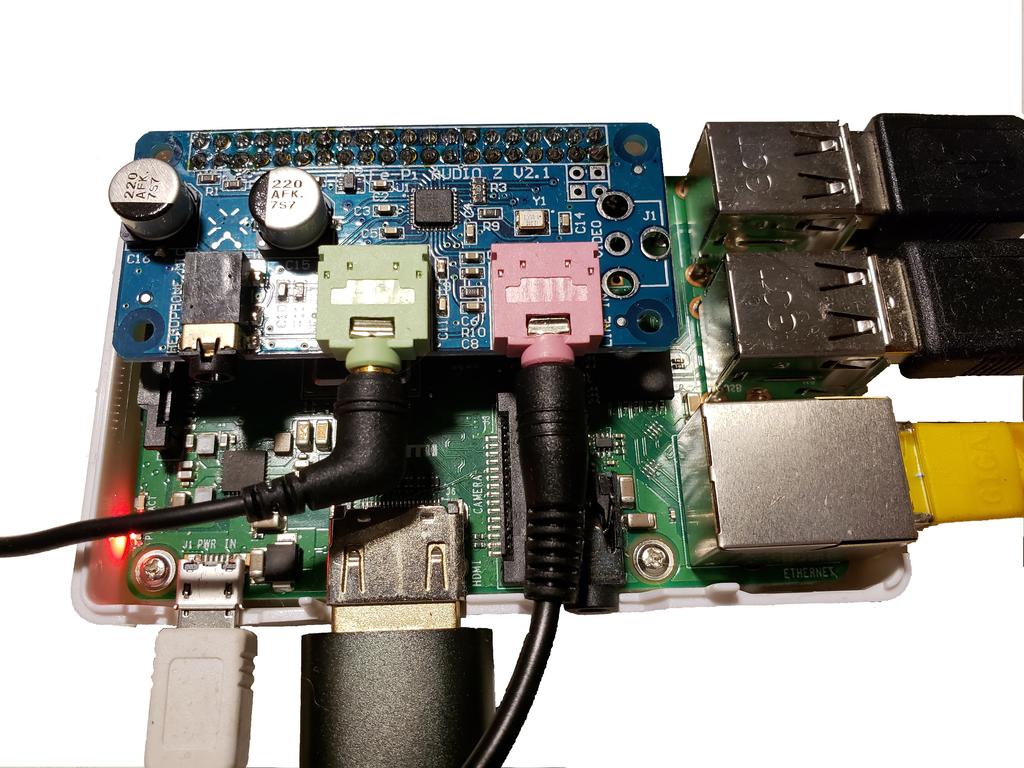
   Other Sound Devices to Consider:
   --------------------------------

      CM108/CM118 USB-based devices (build your own interface):
      ---------------------------------------------------------
      $7 US - Syba SD-CM-UAUD basic sound device which can be had for $7
              https://www.amazon.com/s?field-keywords=SD-CM-UAUD

              Note: Direwolf DEAD AIR ISSUE (RESOLVED):
              -----------------------------------------
                 There is a known Direwolf issue with USB soundcards on older Raspberry Pi boards
                 (3+ and older generations) but NOT on the RPi 5, 400, CM4, or 4

                    https://github.com/wb2osz/rpi-usb-audio-bug
                       and
                    https://bugs.launchpad.net/raspbian/+bug/1819560

                 This "key up but have variable dead TX air time until the modem sounds played" issue
                 also does not happen on X86 machines.  This issue now has a fix and should be in the
                 mainline Linux kernel since about 2021 but until then, there is also a different yet
                 effective workarounds.

                 What's the issue?
                 -----------------
                 What happens here is that Direwolf will key up the radio via the configured
                 GPIO pin but the soundcard will wait some random amount of delay before
                 playing the TNC modem tones.  Some of these delays can be up to 2 seconds!  It's
                 reported that the Raspberry Pi 4 with it's completely new USB chip and software
                 stack (all previous generation Raspberry Pi models use the same older SOC built-in
                 USB chip) does NOT exhibit this issue.

                 The easy and RECOMMEND workaround for this issue on the older Raspberry Pi modems
                 is to either:
                    - Use the newer DWC2 USB stack
                    - Use the OSS sound stack ALSA wrapper

                 More details below


   Kit or Pre-Built Amateur Radio focused USB-based sound devices (usually marketed as "Allstar interfaces"):
   -------------------------------------------------------------------
      - There are families of of sound devices using either the CM119 sound chip that's also found
        in say the Syba sound device or other chips focused on providing a more "integrated" offering
        with minimizing the requirement of creating custom cabling.  These type of devices are commonly
        called "Allstar" devices which is an analog Radio over IP (RoIP) technology similar to Echolink
        and IRLP:

            Nexus DR-X - an Multi-purpose audio routing + RTC device + Buck/Boost power supply HAT board
            $98          intended to connect a seperate sound device (optional Nexus-DRX / Fe-Pi sound HAT
                         recommended) to either an Amateur radio's 6pin jack or RJ45 microphone jack (with or
                         without Fe-Pi like I2S sound device) with electronic mixer controls only - includes
                         a simple plex layer case.
                         - No CAT radio support.
                         https://wb7fhc.com/nexus-dr-x.html

            Digirig - A USB to dual TRRS cable solution for multi-radio support for full sound, PTT, and
            $80       CAT control (for those radios that support it).  $50 for sound device and $30 for
                      pre-made cables (Yaesu 6pin DATA plus CAT cable for example)
                      + HAS CAT support
                      + HAS PTT via serial port support
                      - No TX timeout timer support
                      https://digirig.net/product/digirig-mobile/

            DRA-36 - The Master Communication famiy of fully featured sound devices.  The DRA-36 offers a USB
            $51      to either 6pin "DATA" cable or DB9 TNC2 cable + PTT device (kit or fully built) only.
                     A kit version is intended to connect directly to an Amateur Radio's 6pin jack with physical
                     pots for audio adjustments.  Most DRA units also offer a built-in TX timeout timer based
                     on a 555 timer to avoid hung transmitters (very nice feature) - offers a separate case.
                     - No CAT support
                     http://www.masterscommunications.com/

            DINAH - A USB to 6pin "DATA" cable sound + PTT device intended to connect directly to an Amateur
            $35     Radio's 6pin jack with electronic mixer controls only - includes a separate case.
                    Uses the CM108 GPIO function for PTT.
                    - No CAT support
                    - No TX timeout timer support
                    https://hamprojects.info/dinah/#cmtoc_anchor_id_9


            RIM and RIM-Lite - USB to commercial radio audio connections for setups for Motorola, Alinco,
                   Scom, RLC, etc.
                   - No CAT support
                   http://www.repeater-builder.com/products/usb-rim-lite.html

            DRAWS - A Raspberry PI HAT to dual 6pin "DATA" cable + PTT device + GPS receiver + RTC + Buck/Boost
            $150    power supply intended to connect directly to an Amateur Radio's jack with electronic mixer
                    controls only
                    - case not included
                    - No CAT support
                    http://nwdigitalradio.com/draws/

            Signalink - A popular external USB sound device commonly used for HAMs as they work with many
            $110        different radio combinations and include a auto-VOX-like PTT mechanism.  All Signalink
                        units include isolation transformers for mitigating ground loops, galvanic hum, etc.
                        mostly found with HF communications.

                        NOTE: Older generation Signalink units used cheaper transformers that block WIDE modes
                              like QPSK 4800bps packet, G3RUH 9600bps FSK packet and VARA Wide.  Newer version
                              units have better transformers that fixed this issue.

                        I personally find the Signalink units overly expensive for what they are.  I also find
                        it's pseudo-VOX PTT solution and the variable TX delay knob can create a lot of issues


   - One of the more ultimate solutions are:

        NW Digital DRAWS (complete HAT): http://nwdigitalradio.com/draws/
          - dual radio support, also includes a GPS with PPS support, RTC clock and a wide voltage converter
            for powering the Rpi, and extender header with some GPIO pins and two ADC inputs


   NOT RECOMMENDED but works as a USB sound device:
   ------------------------------------------------
       - If you're looking for something even cheaper, you might try using
         one of these inexpensive CM108 USB-based sound devices commonly found on Ebay. These
         units are commonly found in documentation for setting up an Allstar hotspot, etc.
         Unlike the recommended Syba USB unit mentioned above, these devices don't always include
         any microphone input level control, any audio filters or even include a plastic enclosure
         to protect the electronics to keep costs down.  You'll need to add an additional input
         control like a resistive input volume potentiometer, etc.  My other concern with using
         these inexpensive boards like this is that they can be changed at any time
         for different chips at any time and you won't know it.  The quality of some of these
         units is also VERY poor and you shouldn't be surprised if a new unit is dead on arrival
         (DOA).

            Here is an example URL for more details:
            http://www.marrold.co.uk/2018/04/converting-cm108-usb-fob-for-amateur.html

         NOTE:
         -----
         Raspberry Pi 3+ and older boards don't do well with higher sampling sound cards running
         at say 192Khz, etc.  It's recommended to use a 48Khz sampling soundcard for direwolf:

            https://www.raspberrypi.org/documentation/hardware/raspberrypi/usb/README.md


         NOTE #2:
         --------
         Other sound devices might work but it's known that Direwolf is sensitive to USB devices
         and not all work correctly.  The Syba unit is proven reliable and also doesn't spew RF
         noise on 144.000MHz!

         Tech
         Tangent:  Why am I talking about "noise on 144.000Mhz?  I recommend you give this a little
                   test.  Take your hand held (HT) amateur radio and change it's VFO frequency to
                   144.000Mhz.  Do you hear anything breaking the squelch?  Try walking around your
                   home and you'll probably start finding many strong signals (birdies) opening up
                   the squelch of your HT.  Why is this happening?  Many MANY devices and sound cards
                   use poorly shielded 12Mhz crystal oscillators which is everywhere in modern
                   electronics.  Why does that matter to you?

                   The 12th harmonic of 12Mhz is 144MHz and thus where all the interference comes
                   from!  Tangent over.
20.a Setup the Fe-Pi Audio Z I2S sound device
+-------------------------------------------------------------------------------------------------+
| NOTE: If you're not using a Nexus DR-X sound HAT / Fe-Pi HAT, skip to the next section covering |
|       say CM-108 USB sound devices                                                              |
+-------------------------------------------------------------------------------------------------+

The Fe-Pi Audio Z v2 HAT board is a dedicated sound HAT board that uses the Raspberry Pi's built-in
and dedicated I2S bus.  This audio-specific bus offers a more dedicated connection than say
USB offers on the Raspberry Pi 3+ and older boards.  In addition to the connectivity improvement,
these boards also offer direct stereo LINE-IN and LINE-OUT connections for improved signals.

To get a Fe-Pi board working, you have to do more than just connect the board but it's not hard:

   1. Driver support is included since Linux kernel 4.9.13 (Raspbian Jessie / 8.x or newer).  You
      can also get newer kernels by running "sudo rpi-update" tool

   2. You have to make a quick change to the Rpi boot process to enable the HAT board at the
      Broadcom SOC level.  Do the following:

         sudo vim /boot/config.txt

            Find a line that includes the word "dtoverlay"

            Add a line below it that has the following text (must be a NEW line.. do not add to
            an existing line):

               dtoverlay=fe-pi-audio

   3. Reboot the Rpi

      sudo /sbin/shutdown -r now

   4. Once the Rpi boots back up, login and run the following command to confirm the board
      is recognized:

         dmesg | grep -i fe-pi
         --
         [    8.007458] snd-fe-pi-audio soc:sound: ASoC: CODEC DAI sgtl5000 not registered - will retry
         [    8.010476] snd-fe-pi-audio soc:sound: ASoC: CODEC DAI sgtl5000 not registered - will retry
         [    8.487658] snd-fe-pi-audio soc:sound: ASoC: CODEC DAI sgtl5000 not registered - will retry
         [    8.488264] snd-fe-pi-audio soc:sound: ASoC: CODEC DAI sgtl5000 not registered - will retry
         [    8.664517] snd-fe-pi-audio soc:sound: sgtl5000 <-> 3f203000.i2s mapping ok
         --

   5. OPTIONAL:
      When you enable the fe-pi-audio overlay, you're also enabling the Rpi's I2C subsystem so that alsamixer
      can control the sound chip's mixer settings.  If you have the i2cdetect utility installed (fully described
      in the 16x4 LCD section),  run the following command and you should see the Fe-Pi on the 0x0a address as
      "UU" meaning it's in use:

        sudo i2cdetect -y 1
        --
             0  1  2  3  4  5  6  7  8  9  a  b  c  d  e  f
        00:          -- -- -- -- -- -- -- UU -- -- -- -- --
        10: -- -- -- -- -- -- -- -- -- -- -- -- -- -- -- --
        20: -- -- -- -- -- -- -- -- -- -- -- -- -- -- -- --
        30: -- -- -- -- -- -- -- -- -- -- -- -- -- -- -- --
        40: -- -- -- -- -- -- -- -- -- -- -- -- -- -- -- --
        50: -- -- -- -- -- -- -- -- -- -- -- -- -- -- -- --
        60: -- -- -- -- -- -- -- -- -- -- -- -- -- -- -- --
        70: -- -- -- -- -- -- -- --
        --

Once the board is recognized, go ahead and follow the next soundcard centric sections to test the board.
20.b Identify and test the USB sound device
+-------------------------------------------------------------------------------------------------+
| NOTE: For users using a USB-based CM-108/119 device.. read here!                                |
+-------------------------------------------------------------------------------------------------+

To start, have your USB sound device connected to the Raspberry Pi:

   NOTE:  Plug the sound device it into the Raspberry Pi directly
          (do NOT connect it via a USB hub as there are reported issues issue with the Direwolf
          program and USB packet latencies introduced by hubs


   NOTE #2: If using a Syba USB-based sound device, there is a small green LED on it.
            This is what the LED's behavior means:

            - On SOLID: device is initialized but doing nothing

            - Blinks slowly:  device is recording audio

            - Blinks quickly: device is playing audio


+-------------------------------------------------------------------------------------------------+
| NOTE: All sound devices... continue reading here..                                              |
+-------------------------------------------------------------------------------------------------+

Let's now identify your I2S or USB sound device:

   #First, install some ALSA utilities (if not already installed)
   #
   sudo apt install alsa-utils

   #To view all output capable sound devices:
   aplay -l


Below is what I see on:

   - A Rpi4 running Raspberry Pi OS Bookworm (Debian 12) with a CM108 USB device
     --
     **** List of PLAYBACK Hardware Devices ****
     card 0: Headphones [bcm2835 Headphones], device 0: bcm2835 Headphones [bcm2835 Headphones] <------ Rpi built-in audio output
       Subdevices: 8/8
       Subdevice #0: subdevice #0
       Subdevice #1: subdevice #1
       Subdevice #2: subdevice #2
       Subdevice #3: subdevice #3
       Subdevice #4: subdevice #4
       Subdevice #5: subdevice #5
       Subdevice #6: subdevice #6
       Subdevice #7: subdevice #7
     card 1: vc4hdmi0 [vc4-hdmi-0], device 0: MAI PCM i2s-hifi-0 [MAI PCM i2s-hifi-0]
       Subdevices: 1/1
       Subdevice #0: subdevice #0
     card 2: vc4hdmi1 [vc4-hdmi-1], device 0: MAI PCM i2s-hifi-0 [MAI PCM i2s-hifi-0]
       Subdevices: 1/1
       Subdevice #0: subdevice #0
     card 3: Device [C-Media USB Audio Device], device 0: USB Audio [USB Audio]                <------ USB based soundcard
       Subdevices: 1/1
       Subdevice #0: subdevice #0
     --

   or

   - A Rpi3+ running Raspberry Pi OS Bullseye (Debian 11) with both a Nexus DR-X / Fe-pi and a CM108 USB device
     --
     **** List of PLAYBACK Hardware Devices ****
     card 0: b1 [bcm2835 HDMI 1], device 0: bcm2835 HDMI 1 [bcm2835 HDMI 1]                <------ Rpi built-in audio output
       Subdevices: 3/4
       Subdevice #0: subdevice #0
       Subdevice #1: subdevice #1
       Subdevice #2: subdevice #2
       Subdevice #3: subdevice #3
     card 1: Headphones [bcm2835 Headphones], device 0: bcm2835 Headphones [bcm2835 Headphones]
       Subdevices: 3/4
       Subdevice #0: subdevice #0
       Subdevice #1: subdevice #1
       Subdevice #2: subdevice #2
       Subdevice #3: subdevice #3
     card 2: Audio [Fe-Pi Audio], device 0: Fe-Pi HiFi sgtl5000-0 [Fe-Pi HiFi sgtl5000-0]  <------ Fe-Pi Audio Z I2S based soundcard
       Subdevices: 1/1
       Subdevice #0: subdevice #0
     card 3: Device [Generic USB Audio Device], device 0: USB Audio [USB Audio]            <------ USB based soundcard
       Subdevices: 0/1
       Subdevice #0: subdevice #0
   --


For older versions of Raspberry Pi OS, it might show something like:
--------------------------------------------------------------------

   For a FE-Pi:
   ------------
      "plughw:CARD=Audio,DEV=0"
          vs.
      "card 2: Audio [Fe-Pi Audio], device 0: Fe-Pi HiFi sgtl5000-0 [Fe-Pi HiFi sgtl5000-0]":


   For a Syba USB sound device:
   ----------------------------
      "plughw:CARD=Device,DEV=0"
          vs.
      "card 3: Device [Generic USB Audio Device], device 0: USB Audio [USB Audio]"


   Multiple radios / multiple sound devices:
   -----------------------------------------
         If you're going to be using multiple soundcards, you need to understand about ALSA
         soundcard enumeration which is well detailed here:

         https://github.com/dh1tw/remoteAudio/wiki/Persistent-USB-Mapping-of-Audio-devices-(Linux)

            or

         https://blog.habets.se/2021/12/Linux-Sound-devices-are-a-mess.html


     The first link will help you setup UDEV rules for the simplier cases to be able to reliably
     connect to the same sound card ever time.  If you're just using one soundcard, you won't
     really care about any of this enumeration stuff and that's what this doc will assume for now.


Back to all sound devices:
--------------------------

If you're curious on getting more details on your soundcard, you can display the soundcard's
native sampling rates with this command:

   sudo lsusb -vv | grep -e Audio -e tSamFreq | grep -v -e Descriptor -e bInterfaceClass

On my USB based Syba sound device, I see the following sampling rates.  The Fe-Pi Audio Z
board doesn't seem to show anything:
   --
   iProduct                1 C-Media USB Audio Device
             tSamFreq[ 0]        48000
             tSamFreq[ 1]        44100
             tSamFreq[ 0]        48000
             tSamFreq[ 1]        44100
   --

That above output means this sound card can either natively support 48Khz or 44.1Khz input
sampling.

   If you have a PCI-based card (doesn't work for USB or Fe-Pi base soundcards) or you're
   doing all this in a virtual machine, try using:

      sudo alsa-info --stdout | grep -A 12 -e "Codec:" -e "Audio Input"


Ok, time to do some testing, let's record from the sound card for 10 seconds and puts a
960Kbyte file into the /tmp area:

   Fe-Pi-based soundcard test:
   --------------------------
   #Subsituite in your specific sound device in the place of the string "CARD=Audio,DEV=0"
   #
      arecord -D plughw:CARD=Audio,DEV=0 -t wav -f S16_LE -r 48000 -d 10 /tmp/test.wav

      NOTE:  There are not any LEDs on the Fe-Pi to indicate activity


   USB-based soundcard test:
   -------------------------
   #Subsituite in your specific sound device in the place of the string "CARD=Audio,DEV=0"
   #
      arecord -D plughw:CARD=Device,DEV=0 -t wav -f S16_LE -r 48000 -d 10 /tmp/test.wav

      NOTE:  A Syba sound device's green LED will go from a solid on, to blinking slowly
             for 10 seconds and then go back to being on solid


If this works ok, you should see the text output from the command once it terminates:
   --
   Recording WAVE '/tmp/test.wav' : Signed 16 bit Little Endian, Rate 48000 Hz, Mono
   --


Next test, if you have speakers connected to the Rpi's HDMI monitor (default) or the speaker out jack
on the Pi itself, built-in speakers, you can listen to the recorded file via  the "Default" soundcard
output.  If there aren't any speakers connected to the Rpi, you can use tools like scp to send the
file to another computer that DOES have speakers connected

   #First, test with a known good audio file going to either your HDMI monitor or if your Rpi has a
   # built-in TRS audio jack connected to a set of powered speakers:
   #
   aplay /usr/share/sounds/alsa/Front_Center.wav


   You should see something like the following on the command line:

      Playing WAVE '/usr/share/sounds/alsa/Front_Center.wav' : Signed 16 bit Little Endian, Rate 48000 Hz, Mono


If you don't hear any audio, make sure:

   - if HDMI audio, the sound is turned up on the monitor

   - if using the Rpi speaker out, use amplified speakers or a headphones and turn up the volume

   - Change the audio routing:
      amixer cset numid=3 1   #analog jack
      amixer cset numid=3 2   #HDMI jack

Ok, now try playing the final test is to play the file you just recorded from the steps above with:

   aplay /tmp/test.wav

   # You probably didn't hear anything because there wasn't a microphone connected to the
   # sound device.  That's ok as long as it didn't give any errors


To play the same files through the newly added sound device (assuming you temporally
connected speakers to the output jacks of that board), do:

   Fe-Pi Audio Z I2S USB sound card:
   ---------------------------------
   aplay -Dplughw:CARD=Audio,DEV=0 /usr/share/sounds/alsa/Front_Center.wav
      and
   aplay -Dplughw:CARD=Audio,DEV=0 /var/log/test.wav

 Or

   Syba USB sound card (the device's green LED will go from a solid on, to blinking slowly
             for a dew seconds and then go back to being on solid)
   ---------------------------------------------------------------------------------------
   aplay -Dplughw:CARD=Device,DEV=0 /usr/share/sounds/alsa/Front_Center.wav
      and
   aplay -Dplughw:CARD=Device,DEV=0 /var/log/test.wav


If you select the wrong ALSA device, you might see the error:

     aplay: set_params:1239: Channels count non available


You can now mix and match commands and combine with the Unix "pipe" feature.  Here, we output from
Rpi's built-in output only headphone jack and into say a Syba USB sound card:
20.c Setting up the Sound Device levels for 1200BAUD AFSK Packet Radio
This packet radio example setup is going to use an Alinco DJ-580 HT with a simple GPIO to
PTT circuit similar to the one shown here (more about this later):

   http://www.dunmire.org/projects/DigitalCommCenter/soundmodem/mySoundCardInterface.png


The PTT connection is connected to physical GPIO pin:

   Rpi pin 37 (Broadcom GPIO 26) :: connect this to the PTT circuit or RS232 DB9 pin7 (this is the RS232 RTS signal)
   Rpi pin 39 ( electrical GND ) :: connect this to the PTT circuit or RS232 DB9 pin5 (this is the RS232 GND signal)


On the HT side, I initially set the Alinco DJ-580 knobs to:

      SQL knob          : 0.0 out of 10    (squelch fully open)
      Output Volume knob: 2.9 out of 10
      Power save        : Off
20.d. Sound device Mixer settings
The following audio level setting exercise is CRITICAL step for any properly tuned packet station.
Please review this very carefully section to better understand how to test and your own station's
audio levels.
Alsamixer is a simple but effective ncurses console interface to change sound card levels. To
use it, you use your keyboard's F-keys to select high level things like which sound card,
playback levels, and microphone levels. You then use the cursor keys to navigate around
and change the levels. Now, when making mixer level changes, it's VERY helpful to hear the
audio level changes real time to know things are both changing at all but working the way
you expect to get the basic audio levels right. To do this, try connecting a music device
like your smartphone's headphone jack (hopefully yours still has one) to your chosen Rpi's
sound device's INPUT jack.
Run the command:
# We want to run this mixer program as root to set the main OS system audio levels and not
# a specific user's audio levels
#
sudo alsamixer
Now play a known audio / music file from your smartphone and then run one of these commands
to get the Raspberry Pi to start simultaneously recording and playing the audio back:
#
# Don't forget the trailing "-" at the end of the command line (this is the STDOUT
# system)
Two examples here that will record what's coming from the HT and play it out the soundcard's attached
speaker:
- Fe-pi Audio Z USB device : audio in and audio out on the Fe-Pi - this will record and playback forever
until you hit control-c
arecord -D plughw:CARD=Audio,DEV=0 -t wav -f S16_LE -r 48000 - | aplay -Dplughw:CARD=Audio,DEV=0 -
or
- Syba USB device : audio in and audio out on the Syba - this will record and playback forever
until you hit control-c
arecord -D plughw:CARD=Device,DEV=0 -t wav -f S16_LE -r 48000 - | aplay -Dplughw:CARD=Device,DEV=0 -
Hopefully that worked but maybe not as more mixing settings might be required. If so.. keep reading. You can
also use Direwolf's calibration tones to make sounds. If you'd like to try that, open a new terminal window
on your Rpi (GUI terminal or CLI VTY) and run:
cd /etc/ax25
direwolf -x -a :: Send alternating mark / space tones for 60 seconds
direwolf -x -m :: Send mark tone (1200hz)
direwolf -x -s :: Send space tone (2200hz)
- In alsamixer, use the The "F6" key is used to select the correct sound card
In these examples, I cover both the:
- Fe-Pi Audio Z v2 / WB7FHC I2S-connected sound hat: C-Media USB Audio Device
- Syba USB-connected sound card: C-Media USB Audio Device
Tuning the OUTPUT via alsamixer
--------------------------------
If you have a CM108/119 sound device, read this section. If you have a Nexus DRX I2C sound device, scroll
down to the next page:
CM108 devices:
--------------
- Press the F6 key an select "C-Media USB Audio Device" and then F3 to see the Playback settings
- Press the "F3" key to select the "playback" or output interface on the sound device
+------------------------------------------------------------------------------------------------------+
| CRITICAL: You must ensure the output control sometimes labeled "Speaker" on your sound device is |
| "activated" aka ensuring that the bottom of the verticalliy shown slider control shows a |
| "00' in the very bottom of this vertical box. If it shows "MM", that means the output is |
| currently MUTED aka no audio will be played. It is critical that you hit the "m" key to |
| UN-MUTE this key control. |
+------------------------------------------------------------------------------------------------------+
Here are some example levels to try setting your station to but some customization will be required for you
specific setup:
- Set the "speaker" level to be at "00" (left channel) and "19" (right channel) depending on on how
you've wired your sound device your radio. Use the "z" key to LOWER the left channel's level.
- If you see a "Mic" vertical slider in this "playback view", this control is actually the sound device's
"monitor feature". If you do see it, it's recommended to MUTE it by using the left/right cursor keys
to move over to that vertical sider and hitting the "m" key until you see it show as "MM"
- Auto Gain control - if this control shown on your specific sound card, it is debated if this should
be on or off. I have had good success with this being ENABLED aka it showing as "00"
- Skip the next Nexus DRX / Fi-Pi setion to get to the INPUT for CM108-devices
Nexus DR-X WB7FHC / Fe-pi sound HAT:
------------------------- ----------
The Fi-Pi or the new WB7FHC Nexus DR-X authorized clone of this HAT is a powerful I2S-connected (not USB) sound
device with built-in hardware output equalizers, mixers, line-in/out jacks as well though it's a bit complex
(has 24 controls on the Playback section of alsamixer alone!). The Fe-Pi Audio Z v2 is also a bit weird on where
it puts its controls so I'll describe each function:
Electrically: the Fe-Pi Audio Z offers stereo LINE-OUT audio jacks via the GREEN 3.5mm
three-conductor TRS jack, LINE-IN via the PINK 3.5mm jack, as well as a
HEADPHONE output via the BLACK four-pin TRRS jack. I recommend to use the
LINE-OUT jacks if you the audio levels can work for you (more below)
Mixer Configuration: The Fi-Pi offers a LOT of functionality that most sound devices
don't expose. Below is what I reverse engineered out of it's
settings but the data sheet for it's sound chip also provides
deeper detail if you wish to read it:
https://www.nxp.com/docs/en/data-sheet/SGTL5000.pdf
- In the alsamixer tool, hit the F3 key to see all "playback" settings. Now use the keyboard's
cursor keys to move left and right and starting on the far left and going to the right.
You can see the full description of the control in the upper left corner of your screen under
the "item" label:
PLAYBACK
--------
* the two primary controls for OUTPUT control is PCM for course control
and LineOut for fine control
- "headphone db gain" : Audio playback via the black 4-conductor TRRS connector
** hit the "m" key to MUTE aka disable this input as we are going to
use the green LINE-IN jack instead
- "headphone mux" : select "DAC" - options are "DAC" and "LINE_IN"
**************
** CRITICAL **: select "DAC" or everything coming in through "line_in" will
************** go out the "headphone" jack only, bypassing everything in
your alsa mixer settings!
- "headphone Playback ZC" : MUTE - not 100% sure what this setting really is
** hit the "m" key to MUTE aka disable it
- "PCM" : This is a master output volume that seems to control both the headphone
and line-in output. Small changes here make very large changes to the audio levels.
** RIGHT CHANNEL: Set level to: 75
** LEFT CHANNEL: Set level to: 0 <--- Use the "z" key to lower to ZERO
NOTE: zeroing out the left channel will help you minimize cross-talk
and getting spurious multi-channel decodes of the same packet
Multi-channel Direwolf users / Nexus DR-X HAT users:
Each channel (left / right) is for one dedicated radio. As such, you will
probably want both levels to be at say 75 to start
+--------------------------------------------------------------------------------+
| Audio Level note: |
| |
| The Fe-Pi's Audio Z v2 LINE-OUT audio levels are much lower compared to |
| the HEADPHONE jack as the headphone output includes amplification. This |
| is *EXPECTED*. If your radio's input requires higher levels than what a |
| setting the LineOut setting to 100 and the PCM level of "100", try: |
| |
| - Check to see if your radio's audio IN has it's own gain control. For |
| example, Kenwood V71 and D710 radios have an input gain setting but |
| it can ONLY be set digitally via a MS Windows utility |
| |
| - You might need to switch and use the Headphone jack output instead |
| of using the LINEOUT jack. Remember to lower the output levels first |
| before switching to "headphone" so you don't overdrive anything. |
+--------------------------------------------------------------------------------+
- "LineOut" : This is a STEREO volume for the line-out hack and it's control seems to
make very minor level changes. Depending on how you wire up the
soundcard to your radio, turn up only one channel (say the RIGHT-side
channel):
** RIGHT CHANNEL: Set level to: 58
** LEFT CHANNEL: Set level to: 0 <--- Use the "z" key to lower to ZERO
To maximize your OUTPUT audio level, set this first to 100 and then increase
the PCM level to 100. Please note that running the sound device at 100
can create undesired distortion. If your running into this, please read
the note above about possibly switching to the headphone jack out instead.
Multi-channel Direwolf / Nexus DR-X HAT users:
Each channel (left / right) is for one dedicated radio. As such, so you will
probably want both levels to be at say 58 to start
- "Mic" : not sure why this is here since we're in the PLAYBACK section of the mixer
** Set to 0 (you cannot MUTE this setting)
- "Capture Attenuate" : adds a -6db attenuator on the microphone input (not sure why
this is in the playback section
** hit the "m" key to MUTE aka disable it
- "Capture Mux" : determine what input port to listen to : options are "MIC_IN and LINE_IN"
*************
* IMPORTANT * Use the up/down arrow keys to select: "LINE_IN"
************* - not sure why this is here since we're in the PLAYBACK section of the mixer
- "Capture ZC" : not 100% sure what this is
** hit the "m" key to MUTE aka disable it
- "AVC" : not 100% sure what this is
This control has some interaction with the "AVC hard limiter" control
** leave at default: 0 or hit the M key to MUTE it **
- "AVC hard limiter" : not 100% sure what this is
This setting is used when "Digital Input Mux" is set to DAP.
When "AVC" is set to 0 and this setting it set to to "m" for MUTE,
all DAP-enabled audio playback stops
** leave at default: 0
- "AVC integrator response" : not 100% sure what this is
** leave at default: 33
- "AVC max gain : not 100% sure what this is
** leave at default: 0
- "AVC threshold : not 100% sure what this is
** leave at default: 0
- "BASS 0" : Use when "Digital Input Mux" is set to DAP
Sound Equalization: Deep Bass
** leave at default: 49
- "BASS 1" : Use when "Digital Input Mux" is set to DAP
Sound Equalization: Mid Bass
** leave at default: 49
- "BASS 2" : Use when "Digital Input Mux" is set to DAP
Sound Equalization: Midrange
** leave at default: 49
- "BASS 3" : Use when "Digital Input Mux" is set to DAP
Sound Equalization: Low treble
** leave at default: 49
- "BASS 4" : Use when "Digital Input Mux" is set to DAP
Sound Equalization: High Trebble
** leave at default: 49
- "DAP Mix Mux" : not 100% sure what this is (options: ADC, I2S)
** leave at default: ADC
- "DAP Main Channel" : Volume control when "Digital Input Mux" is set to DAP
** leave at default: 50
- "DAP Mix Channel" : Mix control to add in DAP audio control when "Digital
Input Mux" is set to DAP. Depending on what the "DAP
Mux Channel" is set it, the level of 0, starts with
that signal (say ADC) and as you increase the level,
it adds in the other DAP controlled signal (say I2S)
which adds both volume and delays
** leave at default: 0 **
- "DAP Muxl" : not 100% sure what this is (options: ADC, I2S)
** leave at default: ADC **
- "Digital Input Mux" : not 100% sure what this is (options: I2S, Rsrvd, DAP)
** leave at default: I2S
NOTE: there seems to be some audio delay (buffering)
between the I2S and DAP selection - the "I2S" setting
seems to offer less latency
NOTE2: the DAP option seems to alter the audio playback with
a "brighter" or higher frequency audio output with
a lot more mid-range sound. Do NOT use
NOTE3: The DAP setting enables the BASS 0-4 parameters
controls to change the various bass, mid, low trble, and
high treble levels
---------------------
Audio INPUT interface
---------------------
- Ok, lets move on to the audio INPUT side of the mixer controls. Press the "F4" key in alsamixer to select the
"Capture" or Input interface on the sound device
- CM108 / CM118 based USB sound device
-------------------------------------
- "Capture" to a level of 31 - this is a reasonable place to start
- Make sure you see the RED word "Capture" on the bottom of the vertical slider by using the space bar
- If your sound device shows an AGC / Automatic Gain Control option, it's recommended by WB2OSZ to DISABLE it
for the Direwolf application. It should show an "MM" in the control box to mean "disabled"
- Fe-pi / WB7FHC Nexus DR-X sound HAT:
------------------------------------
Electrically: the Fe-Pi Audio Z v2 offers both LINE-IN audio jacks via the pink 3.5mm three-conductor
TRS jack or MICROPHONE via the black four-pin TRRS jack. I recommend to use
the LINE-IN jack
- "mic db gain" : Audio input level via the black 4-conductor TRRS headphone connector
Default is 0
** Leave to default: 0 as we are going to use the green LINE-IN jack instead)
- "capture" : Primary audio input level control
Default is 80
************
* CRITICAL *: Hit the SPACE BAR to make this item show "L R CAPTURE" in RED letters
************
** RIGHT CHANNEL: Set level to: 80
** LEFT CHANNEL: Set level to: 0 <-- Use the "z" key to lower this to 0
Multi-channel Direwolf / Nexus DR-X HAT users:
Each channel here is one of the two radio connections on the Nexus board (left or
right). As such, so you will probably want both levels to be non-zero
- "AVC integrator response" : Same control as on the Playback control area
** leave at same value as on playback screen: 33 **
- "AVC max gain : Same control as on the Playback control area
** leave at same value as on playback screen: 0 **
- "AVC threshold : Same control as on the Playback control area
** leave at same value as on playback screen: 0 **
- "BASS 0" : Same control as on the Playback control area
** leave at same value as on playback screen: 49 **
- "BASS 1" : Same control as on the Playback control area
** leave at same value as on playback screen: 49 **
- "BASS 2" : Same control as on the Playback control area
** leave at same value as on playback screen: 49 **
- "BASS 3" : Same control as on the Playback control area
** leave at same value as on playback screen: 49 **
- "BASS 4" : Same control as on the Playback control area
** leave at same value as on playback screen: 49 **
- "DAP Main channel" : Same control as on the Playback control area
** leave at same value as on playback screen: 50 **
- "DAP Mix Channel: : Same control as on the Playback control area
** leave at same value as on playback screen: 0 **
All sound deviecs (regardless if a CM108, Nexus DRX, etc):
----------------------------------------------------------
- Press the "F5" key to select "All controls"
- Some specific sound cards don't show any specific AGC (Automatic Gain) controls in
either the "F3 - playback" or "F4 - capture" views but they DO show them in this
view here so it's best to double check here
- If you DO see an AGC control for input, make sure you turn it OFF. It's
important to do so or adjusting your input level will be nearly impossible to do so.
AGC will also mess with Direwolf's own internal AGC mechanisms on receive
- Now hit the ESCAPE key to exit and leave the current audio level settings in place
+----------------------------------------------------------------------------------------+
| CRITICAL: Save your new mixer settings |
| |
| Once you have the packet radio soundcard initially tuned up, now it's time |
| to save the soundcard settings: |
| |
| sudo alsactl --no-ucm store |
| |
| Running this command will store all of these packet mixer settings but all other |
| sound device mixer level settings into the /var/lib/alsa/asound.state file. We will |
| soon setup a command to restore those levels upon every boot in a moment. |
+----------------------------------------------------------------------------------------+
20.e. Confirm Clean Silence from the Sound device
This check is needed as a *lot* of USB sound devices will pass on noise from dirty power
sources through your radio in the form of dirty audio.  Noisy audio will severely harm the
software TNC's digital signal processing.  To properly check for this, do the following:

     a. Create an empty (and noise free) 15 second WAV file - output file should be about 240kbytes


        #RECOMMENDED: Recording from the soundcard interface while nothing is connected to it

           Fe-Pi Audio Z v2-based soundcard test:
           --------------------------------------
              arecord -D plughw:CARD=Audio,DEV=0 -t wav -f S16_LE -r 48000 -d 15 /tmp/15sec-silence.wav

              NOTE:  There are not any LEDs on the Fe-Pi to indicate activity


           USB-based soundcard test:
           -------------------------
              arecord -D plughw:CARD=Device,DEV=0 -t wav -f S16_LE -r 48000 -d 15 /tmp/15sec-silence.wav

              NOTE:  A Syba sound device's green LED will go from a solid on, to blinking slowly
                     for 10 seconds and then go back to being on solid


        #NOT Recommended - This recording approach function might be broken with recent versions of
                           Raspbian where it creates a loud clicking sound on recording

              arecord -c 2 -d 15 -f S16_LE -r 48000 -t wav -D null /tmp/15sec-silence.wav


        You should see the following output:

           Recording WAVE '/tmp/15sec-silence.wav' : Signed 16 bit Little Endian, Rate 48000 Hz, Stereo


     b. Temporarily disconnect the packet radio from the soundcard's chosen playback jack,
        connect in a pair of headphones to the soundcard, and listen to the playback the silence
        sound file:


           Fe-Pi-based soundcard test:
           ---------------------------
           aplay -Dplughw:CARD=Audio,DEV=0 /tmp/15sec-silence.wav


           USB-based soundcard test:
           -------------------------
           aplay -Dplughw:CARD=Device,DEV=0 /tmp/15sec-silence.wav


        You should see the following output:

           Playing WAVE '/tmp/15sec-silence.wav' : Signed 16 bit Little Endian, Rate 48000 Hz, Stereo


        Carefully listening to the audio, you should first hear the noise floor increase a little bit
        in the headphones but:

             - There should be no whine, buzzing, or clicking.  The audio should be completely noise
               free.   If it's NOT, you must work to improve that audio.. check the output mixer settings,
               try a different sound device, etc.

          NOTE:  If trying to use the NUL approach above, Raspbian Buster(06/30/19) and Jessie (08/29/17)
                 seems to create a very pronounced TICKING sound on the created recordings.  This is created
                 on a both a Raspberry Pi and an X86 Centos box.  Inspecting the file in Audacity shows the
                 ticks so I think there is a bug in the "arecord" program,
20.f - Setting the right audio levels for AFSK packet tones
Now that you're familiar how to change the levels on the soundcard side, I recommend to
read and then RE-READ:

   http://www.febo.com/packet/layer-one/transmit.html

Read the "The No-Test-Equipment Packet Adjustment System" section to learn how to finely
tune your packet signal levels.  The "no-Test-Equipment packet adjustment system" section on this page
will get your radio's AFSK1200 levels to be pretty close to perfect.  Remember, the adjusting these
levels is a COMBINATION of both the levels coming in/out of your radio as well as the  the Raspberry
Pi's soundcard.  You MUST adjust both components to have and effective and functioning packet station.

   NOTE:  While the Febo approach work pretty well for 1200bps AFSK signals, it WON'T work very well
          for 9600bps G3RUH FSK signals.  You'll need more accurate tools than your ears.  Tools
          like a deviation meter, occiloscope, etc. is required here.


To send AFSK1200 specific calibration tones from Direwolf while following this guide, you can use the
series of commands:

     direwolf -x -a    :: Send alternating mark / space tones
     direwolf -x -m    :: Send mark  tone (1200hz)
     direwolf -x -s    :: Send space tone (2200hz)


Once you have the soundcard levels tuned per this guide, save the new soundcard levels:

   sudo alsactl --no-ucm store

It's worth noting that if you aren't going to be using this document's /etc/ax25/ax25-up.new startup
script, the script already includes:

   sudo alsactl --no-ucm restore

If you are writing your own startup script, make sure you include this command in your scripts to reliably
restore the soundcard levels.  The level settings are stored in /var/lib/alsa/asound.state when run via "sudo".
21. BEWARE of the sound device and radio microphone bias DC voltage
IMPORTANT: Understanding output Bias Voltage on the Microphone Jack:
--------------------------------------------------------------------
Before you connect any radio to your soundcard, it's CRITICAL that you check to
see if there is a voltage here or you can DAMAGE your radio.  You need to check if:

   1) Does your SOUND DEVICE's input or micro jack provide a "bias" voltage
      for condenser-type microphones?  Microphone jacks usual do; line-out ports
      usually don't)

   2) Does your RADIO's microphone jack provide a "bias" voltage for
      condenser-type microphones (it probably does)?

On my Syba USB sound device, it puts out +5.0v on the tip of the mono-style TRS-tyle
microphone jack connector.  I've checked with the CM108 schematics and also it's programming
API and this voltage cannot be turned off via software.  As such, it's CRITICAL that you
connect a 10uF capacitor inline aka between the soundcard's microphone input and your radio's
audio output to remove this voltage.  A inexpensive ceramic capacitor is preferred but a
small electrolytic capacitor will work fine as well.

   NOTE:
        if you use an electrolytic style cap, make sure the POSITIVE lead is
        connected to the sound-card side (the site that's providing the voltage)

Once you've checked the sound device's microphone side, now check the radio's microphone
jack as well and if it also creates a bias voltage, it too will need a capacitor.
22. Choosing GPIO pin for the radio PTT line
To interface the Rpi to your radio, you need an interface or mechanism to assert the radio's
PTT.  Most radios offer this via different methods depending on their form factor, price
point, etc.:

   - NOT recommended  : Radio enabled to use VOX (listen for audio and key up radio
                        automatically

   - RECOMMENDED:     : Specific input connection on radio selectively connected to ground
                        usually connected to a GPIO pin

   - Less Recommended : Some radios offer a data connection to the radio via either RS232
                        or USB to use the CAT procotol to tell the radio to key up or unkey.
                        This option is less recommended here as few VHF radios officially
                        offer CAT control.  CAT control is managed in the Linux world using
                        tools like HamLib, FLrig, OmniRig, etc.  When using CAT control,
                        there is more latency for the radio to be keyed up compared to the
                        GPIO or RS232 methods.


The Raspberry Pi's GPIO header makes the use of the "specific input connection" for PTT
VERY easy to do and it's also both the most reliable and the lowest latency method.  This
document covers the GPIO method including which GPIO pin on the Rpi's header to use and
why.

IMPORTANT:
----------
   It's VERY important to the reader to understand that some but NOT all GPIO pins on different
   Raspberry Pi models are pulled HIGH (+3.3v) ---by default---.  This also can change due to
   different kernel versions used in different version of the operating system (which can be very
   frustrating).  Determining these details is obviously complicated but it's critically important
   to understand this because by using one of the WRONG pins, your radio may key up when your
   Raspberry Pi is rebooting or is down and STAY keyed up.  That's very bad.

   You can read more about this here:
      https://www.raspberrypi.org/forums/viewtopic.php?t=35321

   You can find out which pins are initiated HIGH here:

      Newer Raspberry Pi versions and their specific data sheets:
      --
      https://www.raspberrypi.org/documentation/hardware/raspberrypi/


      Raspberry Pi Model A, B, B+, the Compute Modules, and the Raspberry Pi Zero
      ARM Peripheral spec sheet
      --
      https://www.raspberrypi.org/documentation/hardware/raspberrypi/bcm2835/README.md -->
        https://www.raspberrypi.org/documentation/hardware/raspberrypi/bcm2835/BCM2835-ARM-Peripherals.pdf


RECOMMENDED:
------------
The Raspberry Pi 4, 3+, 3, 2, Zero-W, Zero, and A/B+ have the larger 40pin connector
with additional GPIO pins:

      Raspberry Pi physical pin 29 - Broadcom GPIO  5
      Raspberry Pi physical pin 31 - Broadcom GPIO  6
      Raspberry Pi physical pin 32 - Broadcom GPIO 12
      Raspberry Pi physical pin 33 - Broadcom GPIO 13  <----- My DCD recommendation
      Raspberry Pi physical pin 35 - Broadcom GPIO 19
      Raspberry Pi physical pin 36 - Broadcom GPIO 16
      Raspberry Pi physical pin 37 - Broadcom GPIO 26  <----- My PTT recommendation
      Raspberry Pi physical pin 38 - Broadcom GPIO 20
      Raspberry Pi physical pin 40 - Broadcom GPIO 21


Getting into the details:
-------------------------
Most newer Raspberry Pi hardware such as 3+ and Rpi v2, the following GPIO pins are
initialized HIGH upon boot which is NOT what we want with the PTT transistor
circuit recommended here:
   --
   GPIO 2
   GPIO 3
   GPIO 4
   GPIO 7
   GPIO 8
   possibly GPIO 14 too
   --

If you were to use one of these pins with the simple PTT transistor circuit mentioned
in this section, you'd then find that whenever your Rpi is rebooting or is powered off,
it would leave your radio keyed up (PTT asserted) until you disconnect the cable!
That's very BAD!  So... I advice to NOT use one of those GPIO pins mentioned above.


Ok, then what GPIO pins should you use?  Well, the Rpi line of SBCs can have their
various GPIO pins connected to several other "alternative" functions available in the
Broadcom SOC ASIC depending on which overlay is selected which alters a given GPIO's
"mode".  There are *LOTS* of either incorrect or legacy information out on the Internet
on this topic as many sites don't show the alternative modes for each of the pins.
Below is one of the better GPIO pin diagrams out on the web showing the different pins
and their various modes.  Pay specific attention to the different *colors* on the diagram:

   RECOMMENDED
   -----------
   Rpi pinout graphic (doesn't include the new Rpi 4 alternative layouts if you care)
   ----------------------------------------------------------------------------------
   http://pinout.xyz/


   RECOMMENDED
   -----------
   For those of you running newer versions of Raspberry Pi OS, try running the
   command "pinout" on the command line to see an Ncurses diagram of your GPIO pins
   and other hardware details of your Pi's hardware.

   The Bookworm-based version of Raspberry Pi OS now comes with the "gpioinfo" tool give
   substantially more details as well.


   Here are some other good URLs to check out for different overlay maps on different models
   of Raspberry Pi (official documentation):

     - https://www.raspberrypi.org/documentation/usage/gpio/

     - Raspberry Pi 2 and 1B+
       https://keytosmart.com/wp-content/uploads/2014/07/Raspberry-Pi-GPIO-Layout-Model-B-Plus.png


Per the Direwolf User Guide documentation, it has the following GPIO pin recommendations:

   Raspberry Pi physical pin 11 - Broadcom GPIO 17
     or
   Raspberry Pi physical pin 15 - Broadcom GPIO 22
     or
   Raspberry Pi physical pin 16 - Broadcom GPIO 23
     or
   Raspberry Pi physical pin 18 - Broadcom GPIO 24
     or
   Raspberry Pi physical pin 22 - Broadcom GPIO 25


   +---------------------------------------------------------------------+
   | My recommended GPIO pin for All Raspberry Pi models (Rpi 5 is TBD)  |
   |  because this pin doesn't have any other primary or alternative     |
   |  GPIO mode functionality (additional I2C, I2S, SPI, etc. function): |
   |                                                                     |
   |                  Rpi pin37 (Broadcom GPIO 26)                       |
   |                  Rpi pin39 ( electrical GND )                       |
   |                                                                     |
   +---------------------------------------------------------------------+


BTW, for use with Direwolf, there is the optional DCD indicator feature to assert
a GPIO pin when a valid packet HDLC data sequence is detected.  I find this indicator
as pretty useful to see though it can be prone to some brief false indication.  If
you want to try this, connect an LED and a 470 Ohm resistor to a different available
GPIO pin to use it.


Here is a master list of all GPIO pins used in this document for various services
documened in different sections of this doc on a Raspberry Pi 3:

   +---------------------------------------------------------------------------------+
   | Master 40pin Raspberry Pi header connection chart:                              |
   |                                                                                 |
   |     Direwolf PTT signal:                                                        |
   |     --------------------                                                        |
   |      Rpi pin 37 (Broadcom GPIO 26) :: connect this to the PTT circuit           |
   |      Rpi pin 39 ( electrical GND ) :: connect this to the PTT circuit           |
   |                                                                                 |
   |                                                                                 |
   |     Direwolf DCD signal:                                                        |
   |     --------------------                                                        |
   |      Rpi pin 33 (Broadcom GPIO 13) :: connect to cathode of LED                 |
   |                                       (short lead / smaller metal within LED)   |
   |      Rpi pin 34 - GND              :: connect to 470 Ohm resistor and other     |
   |                                       side of resistor to anode of LED (long    |
   |                                       lead / larger metal inside LED)           |
   |                                                                                 |
   |     PiShutdown button:                                                          |
   |     ------------------                                                          |
   |      New Native Method                                                          |
   |         Rpi pin 11 (Broadcom GPIO 17  :: connect to 10k resistor, connect other |
   |                                          side of resistor to one side of a      |
   |                                          momentary switch                       |
   |               or                                                                |
   |      Older Python method                                                        |
   |         Rpi pin 18 (Broadcom GPIO 24) :: connect to 10k resistor, connect other |
   |                                       side of resistor to one side of a         |
   |                                       momentary switch                          |
   |              and                                                                |
   |      Rpi pin 20 - GND              :: Connect to other side of momentary switch |
   |                                                                                 |
   |                                                                                 |
   |     I2C for LCD display showing Rpi + Packet stats                              |
   |     ----------------------------------------------                              |
   |       Rpi pin 2 - +5v for LCD backlight                                         |
   |       Rpi pin 3 - I2C Data                                                      |
   |       Rpi pin 5 - I2C CLK                                                       |
   |       Rpi pin 6 - GND                                                           |
   |                                                                                 |
   |                                                                                 |
   |     I2S buss for Fe-Pi (not needed for users using USB-based sound device       |
   |     ---------------------------------------------------------------------       |
   |       Rpi pin 33 - I2S clock                                                    |
   |       Rpi pin 38 - I2S buss audio input                                         |
   |       Rpi pin 40 - I2S buss audio output                                        |
   |       Rpi pin  ? - GND                                                          |
   |                                                                                 |
   |                                                                                 |
   |     PWM fan control                                                             |
   |     ---------------                                                             |
   |      Rpi pin 40 (Broadcom GPIO 20)  - PWM fan control vs. Fe-Pi I2S buss audio  |
   |                                       output -- This is a potential conflict    |
   |                                       but the Pis 40pin header ONLY has one PWM |
   |                                       capable pin                               |
   +---------------------------------------------------------------------------------+


   +---------------------------------------------------------------------------------+
   | GPIO unix permissions reminder:                                                 |
   |                                                                                 |
   |   It's critical that whatever username runs the direwolf program, that user     |
   |   must be given the required Unix permissions to access the GPIO pins.  This is |
   |   covered in detail of the Direwolf section using the "usermod" Unix command.   |
   |   Without this permission, Direwolf will simply fail to key up your radio and   |
   |   you'll never know why!                                                        |
   |                                                                                 |
   +---------------------------------------------------------------------------------+
23. Connecting your Radio to the Sound device with tips
The choice of which radio to use for packet radio depends on several factors:

   1. Your budget

   2. Do you want 1200bps packet (APRS and most packet) or faster (2400bps, 4800bps, 9600bps, etc)
      Packet faster than 1200bps is rather uncommon for a variety of reasons

   3. How reliable do you want your station to be

   4. How much hair do you want left on your head after you complete this project


Generally speaking, I recommend to ONLY use a MOBILE RADIO running at 25watts that has
a 6pin DATA jack on the rear of the radio.  This increases your cost (item #1 above) but
doing this will dramatically help you on items #2, #3, and #4 above!   Some possible
recommendations can be found here:

   https://groups.io/g/nwaprs/wiki/3574


Do consider that with anything posted on the the Internet, take that list with a serious grain of
salt as it also mentions the use of Baofeng radios (NOT RECOMMENDED).

   Important note on why NOT to use cheap radios like Baofeng:
   -----------------------------------------------------------
   The differences between different Baofeng and other cheap voice-grade amateur radios radios
   including Radiooddity, TYT, and all the other Baofeng re-badges, clones, etc.  of the same
   make/model can be appalling.  The quality of these radios from one physical unit to another
   can be all over the map due to terrible production, QA, etc.

   Yes, while they can be decent voice radios for most users (though RF spectrally, they are known
   create terrible RF splatter), it's very difficult to find units that will RELIABLY work as a
   *packet radio*.  I know people hate to hear it and they always continue to try and try to make
   them work but review the Direwolf email list and see how many people solved various issues by
   just replacing the radio:

      https://groups.io/g/direwolf/search?p=created%2C0%2C%2C1%2C2%2C0%2C8789&q=baofeng


Building your own PTT assert circuit
------------------------------------
There are multiple ways to connect the RPi to your radio's PTT line depending on the radio, etc.
and it depends on what you picked as a sound device and/or solution from the above section.
If you went with a complete solution like the Nexus DR-X, Digirig DINAH, DRA-36, etc, solutions
mentioned in a previous section here, the PTT circuit and cabling is already solved.  This
section is assuming you're building your own simple PTT circult which is both very reliable
but inexpensive too!


An ideal solution is to use an opto-isolated transistor circuit such as:

   https://www.nf8m.com/nf8m/rig-control-and-keying/

This type of circuit can be easily and safely connected to a Raspberry Pi's GPIO pins.
Alternatively, I've successfully used this simple transistor circuit with various HTs:

   http://www.dunmire.org/projects/DigitalCommCenter/soundmodem/mySoundCardInterface.png

   +---------------------------------------------------------------------------------------+
   | CRITICAL NOTE:                                                                        |
   | --------------                                                                        |
   | Different radios can have different methods to make the required electrical           |
   | connection and you will need to change / conform the connection to your specific      |
   | radio.  For example, I've since moved to using a Alinco DJ-580 and it's PTT           |
   | connection is SIGNIFICANTLY different than what's used for a say a Kenwood TH-F6A.    |
   |                                                                                       |
   | Unless you modify the connections to suit your radio (also ensure key DC voltage      |
   | blocking capacitors are in place as mentioned in a previous section), you run the     |
   | real risk of damaging your USB sound card *and* the radio itself!                     |
   +---------------------------------------------------------------------------------------+


Other possible radio cabling solutions:

   - Easy Digi isolation kit : This includes an opto-isolator for PTT which also includes
     audio isolation transformers:

        https://www.ebay.com/sch/i.html?_from=R40&_trksid=p2380057.m570.l1313.TR0.TRC0.H0.Xeasydigi.TRS0&_nkw=easydigi&_sacat=0

     This kit solution works well for HF and 1200bps AFSK packet but it will NOT work for say
     4800bps QPSK, 9600bps G3RUH FSK packet, and the VARA-Wide mode as the transformers limit
     the audio passband bandwidth too much.


   - Direwolf recommended timeout-limited PTT circuit that's found in Direwolf's
     Raspberry-Pi-APRS.pdf doc found at

        https://github.com/wb2osz/direwolf/blob/master/doc/Raspberry-Pi-APRS.pdf

     This is an extra-safe design as the design itself will prevent any hung transmitter
     situations due to including a 555 timer!


   - A nicer solution is to get a nice PCB version of WB2OSZ's circuit above which is
     available for order here as designed by James N7SET.  You would need to get this simple
     PCB printed out via various PCB vendors:

        https://github.com/jaymzx/RPi-WD-Packet-Interface


   - You could then put either these two circuits on this little Raspberry Pi proto HAT:

        https://www.adafruit.com/products/2310

     With everything here, you'll then have a very slick setup that you can easily move from
     Raspberry Pi to Raspberry Pi!


The building of the cable harness + PTT circuit is beyond the scope of this document.  If you
have problems / questions, feel free to contact me and I'll try to help out but you might get
faster / better support sending help requests to various email groups such as:

   direwolf@groups.io
   RaspberryPi-4-HamRadio@groups.io
   etc


Assuming you successfully created a working radio interface cable to connect the radio to
the Raspberry Pi sound device AND GPIO pins, please double check:

   - You've ensured that the microphone jacks on both the radio AND the soundcard don't have
     a DC bias voltage (above).  If they do, it's CRITICAL that you install a small DC blocking
     capacitor on both lines to remove those voltages

   - On the radio, make sure the squelch is all the way open (static noise all the time) and
     that the output speaker volume on the radio is LOW (but not off) to start off with

   - If you're using an HT type radio, make sure that you disable any "RX power saver" as
     well as the Automatic power off features of the radio.  If you don't disable both of these,
     the radio will either miss part of the beginning packets and/or have the radio go to
     sleep on you!
24. Compile, Configure, and Test Direwolf
Direwolf is a modern multi-platform soft-TNC meaning that the computer does all the modem sound
processing as well as has a full APRS and AX.25 stack built-in. Direwolf's decoding system
is one of the best available and can decode all kinds of terrible signals. In addition to
classic AX.25 packet support, Direwolf supports:
- support for many different RF speeds including 300, 1200, 2400, 9600bps modes (and more)
- full APRS stack with Igate and APRS-tt (Touch Tone) support
- full digipeater and connected-mode digipeating support
- AX.25 v2.2 support with significant protocol improvements and optimizations
- FX.25 for more robust HF operation
- Other protocol support including IL2P, AIS, EAS SAME, etc
- AGW and KISS-TCP support to allow for other packet programs to use the TNC over your network
- much much more
Anyway, it's time to compile up the newest version of Direwolf! This all assumes your external
SDD/HDD storage is still mounted per the previous document section or you acknowlege the
somewhat-low risk of compiling stuff via the SD card. Anyway, let's get started!
NOTE: If you intend to run a remote Direwolf iGate that might have unreliable Internet
connectivity), it's highly recommended to install an RTC (real time clock) on your
Pi to let Direwolf properly timeout old packets. Please see the RTC section later
in this document on how to set this up.
a. First install the required dependencies to build the minimal Direwolf
NOTE: As of Direwolf 1.7, it is REQUIRED that you have various GPS software library components
installed or the Direwolf *packaging* stage will fail. If you really don't want to install
the GPS libraries (you don't have to enable), then manual workarounds will be required.
#Required base libaries to compile Direwolf
#
sudo apt -y install libasound2-dev unzip libudev-dev
#Install required GPS libraries
#
sudo apt -y install gpsd libgps-dev
# Though we installed the required GPS libraries, we don't want gpsd to be running
# unless you specifically want it. For now, let's DISABLE it:
sudo systemctl stop gpsd
sudo systemctl stop gpsd.socket
sudo systemctl stop system-gpsdctl.slice
sudo systemctl disable gpsd
sudo systemctl disable gpsd.socket
+--------------------------------------------------------------------------------------------+
| IMPORTANT NOTE #1 - gpsd versions |
| |
| Pay attention to what version of gpsd gets installed. If the system installs gpsd |
| v3.22 (various Raspberry Pi OS details below), there are two known issues with that |
| and Direwolf when using features like smartbeaconing and time-stamps being 1024 weeks |
| behind on some old GPS hardware. You can find more details here: |
| |
| https://groups.io/g/direwolf/topic/92088377#6752 |
| https://forums.raspberrypi.com/viewtopic.php?t=336887 |
| |
| Here are the known versions of gpsd insalled with various versions of Raspberry Pi OS: |
| Raspberry Pi OS 12 - Bookworm - comes with 3.22-4.1+b1 :: ** unclear if repaired ** |
| Raspberry Pi OS 11 - Bullseye - comes with 3.22-4 :: ** BROKEN ** |
| Raspberry Pi OS 10 - Buster - comes with 3.17-7 :: OK |
| Raspberry Pi OS 9 - Stretch - comes with 3.16-4 :: OK |
| |
| The proper fix is to get and install GPSd v3.23 or a newer version of Direwolf that |
| supports that version of gpsd. That generally means Direwolf v1.7 or newer. This |
| document does cover the installation of final Direwolf 1.7 release. |
| |
+--------------------------------------------------------------------------------------------+
+--------------------------------------------------------------------------------------------+
| IMPORTANT NOTE #2 with gpsd, serial ports and IPv6: |
| |
| |
| Serial ports: By default, gpsd thinks that all serial ports are GPS receivers and it |
| #1 should manage them. That's pretty silly if you ask me so let's turn that |
| off. To do so, change the following line: |
| |
| sudo vim /etc/default/gpsd |
| -- |
| USBAUTO="false" |
| -- |
| |
| Serial ports: If you connect a USB to serial adapter and it keeps creating devices like |
| #2 /dev/gps0, when you run the command: |
| |
| ls -la /dev | grep ttyUSB |
| |
| These /dev/gps* devices are actually being created via udev! To disable |
| bypass this, do the following: |
| |
| sudo cp /lib/udev/rules.d/60-gpsd.rules /etc/udev/rules.d/ |
| vim /etc/udev/rules.d/60-gpsd.rules |
| - edit this file and find any matching USB VID:PIDs to your USB |
| to serial adapter and DELETE those lines |
| |
| |
| IPv6: If you disabled (or attempted to disable IPv6 on your system per the section |
| above, you might run into an error installing or updating gpsd. This is a |
| known bug per: |
| |
| https://bugs.debian.org/cgi-bin/bugreport.cgi?bug=818332 |
| |
| To work around this, do the following (per the bug report): |
| |
| Edit the /lib/systemd/system/gpsd.socket file and REMOVE or comment out the line: |
| |
| sudo vim /lib/systemd/system/gpsd.socket |
| -- |
| ListenStream=[::1]:2947 |
| -- |
| |
| then run to retry the package config: |
| |
| sudo apt -f install |
+--------------------------------------------------------------------------------------------+
#Important: With Raspberry Pi OS Bookworm 12.2 (3/12/24) and the new Linux 6.6.20 kernel, there
# is a new (more standardized) way to control GPIO pins. This is important as I recommend
# to use them to assert the PTT signal. See the following URLs for more details
#
# https://github.com/wb2osz/direwolf/issues/503
#
# # Direwolf Radio Interface Guide - Section 7.2.1
# https://github.com/wb2osz/direwolf-doc/blob/main/Radio-Interface-Guide.pdf
#
sudo apt -y install gpiod libgpiod-dev
b. Ok, lets' get down to building Direwolf
Enter the compiling area and make it writable by users in the "adm" group
cd /usr/src/archive/Rpi-scratch/
mkdir direwolf
cd direwolf
c. Get a copy of the Direwolf sources
You have two choices here to WHICH version of Direwolf to build:
1. REQUIRED: If you are using Raspberry Pi OS Bookworm that's up to date AND you are looking to
use the GPIO pins to assert the PTT signal to your radio like how these instructions
recommend, you MUST use the bleeding edge Direwolf v1.8-DEV branch. See
https://github.com/wb2osz/direwolf/issues/503#issuecomment-1826463108 for the details.
The short answer here is Bookworm 12.2 has deprecated GPIO access via the sysfs
interface and have moved to a more universal GPIO daemon approach. If you do NOT use
the new Direwolf 1.8-DEV branch code and try to start Direwolf v1.7 on Bookworm 12.2,
you will see the following FATAL error:
--
Dire Wolf version 1.7
Includes optional support for: gpsd cm108-ptt
Reading config file /etc/ax25/direwolf.conf
Audio device for both receive and transmit: plughw:1,0 (channel 0)
Channel 0: 1200 baud, AFSK 1200 & 2200 Hz, E+, 44100 sample rate / 3.
Error writing "26" to /sys/class/gpio/export, errno=22 <---------------------------
Invalid argument
--
1. RECOMMENDED: If you're NOT using the GPIO pins on a Raspberry Pi with Raspberry Pi OS Bookworm,
the "master" branch which is now at v1.7 as of 10/29/23 has many improvements,
fixes, etc. over the previous v1.6 release that came out on 01/01/21. You can
find it and any newer mainline releases at:
https://github.com/wb2osz/direwolf/releases
2. NOT RECOMMENDED: As of 10/28/23, the "dev" or development branch of Direwolf has moved on to
supporting the evanual v1.8 release which supports things like gpiod for supporting
many more SBC boards, adding new functionality, features, etc. and should be
expected to break from time to time. If you like to try out bleeding edge features
and long term relibility is less of an issue, then go ahead and choose this
route.
c.1: RECOMMENDED as of 03/16/24: Go with the DEV branch version of Direwolf for Direwolf v1.8 to
support Raspberry Pi OS Bookworm
#You should be in the /usr/src/archive/Rpi-scratch/direwolf/ directory per instructions above
#
git clone https://github.com/wb2osz/direwolf.git
cd direwolf
git branch -r
git checkout dev
cd ..
24.a. LEGACY: Direwolf Dead TX airtime workarounds

     -----------------------------------------------------------------------------------
     ** LEGACY Details:                                                               **
     **                                                                               **
     **         If you are NOT using an old Raspberry Pi OS version, you can SKIP     **
     **         this workaround section and continue reading starting at the          **
     **         24b.direwolf-builddeps section.                                       **
     **                                                                               **
     **   This legacy section is still included in this document for historical       **
     **   preservation to possibly help some specific users for specific use-cases    **
     -----------------------------------------------------------------------------------


     IMPORTANT for OLD OS versions:
     ------------------------------
     This serious bug issue is / isn't an issue on the following OS releases:

          NOT IMPACTED - Raspberry Pi OS Bookworm - kernel 6.6.20, 6.1.0
          NOT IMPACTED - Raspberry Pi OS Bullseye - kernel 6.1.0
          NOT IMPACTED - Raspberry Pi IS Buster   - kernel 5.10.103
          IMPACTED     - Raspberry Pi IS Stretch  - kernel 4.19.66
          IMPACTED     - Raspberry Pi IS Jessie   - kernel ???


     If you're using a USB based sound device like a Syba CM108 device (not an I2S-based sound device
     Nexus DR-X / Fe-Pi Audio Z v2) HAT board connected to ANY older Raspberry Pi model SBCs like RPi
     3B+, 3, 2, Zero-W, Zero, 1+, 1) **BUT NOT a RPi4 / CM4 / Rpi400** or other newer Raspberry Pi
     hardware versions, there is a known issue of Direwolf transmitting random amounts of "dead
     airtime" before the actual AX.25 modem sounds are transmitted the airwaves.  You can read more
     about this "Raspberry Pi USB DWC" bug at:

        https://github.com/raspberrypi/linux/issues/3883
           and
        https://github.com/wb2osz/rpi-usb-audio-bug
        https://github.com/wb2osz/direwolf/issues/194
        https://bugs.launchpad.net/raspbian/+bug/1819560

     To summarize this dead airtime issue, the Raspberry Pi / Raspbian OS kernel version has a
     customized / modified USB stack compared to the mainline Linux USB stack that has a USB bug
     specifically impacting USB sound card devices.  This bug has been fixed in bleeding edge
     Raspberry Pi Linux kernels newer than 5.4.70.


     NOTE: It was previously mentioned in this doc and it's no longer recommended to use this
           "Dead TX airtime" workaround.  Older Rpi HW owners could use a work-around using the
           legacy OSS sound system (the Linux sound server before ALSA).  Unfortunately, this
           legacy OSS sound support was ALSO accidentally disabled from the Raspberry Pi OS kernel.
           This OSS audio issue was recently re-added in (see URLs above) but going the OSS
           work-around route is still NOT recommended regardless.


     There are several options to address this USB-only bug:

        Option #1: RECOMMENDED: Use the newer DWC2 Raspberry Pi OS USB kernel module for any
                   users using a USB sound device:

                   Only Rpi 0, 1, 2, 3, 3+ users running Raspberry Pi OS "Buster" version can use
                   the alternative "DWC2" USB stack which is now the default USB stack used by all
                   new Raspberry Pi SBC hardware including the Rpi4 / Rpi400 / CM4 hardware.

                   To try this option, it's first recommended to first make a backup of your SD card
                   (a method is recommended in the appendix of this doc).  Once you're ready, edit the
                   /boot/config.txt file and find one of the multiple possible lines starting with
                   "dtoverlay".  Add the following line:

                      sudo vim /boot/config.txt
                      --
                      dtoverlay=dwc2
                      --

                   Once added, reboot your Raspberry Pi.  Once it's back up, log into your pi and
                   run the command:

                      lsmod | grep dwc2

                  to confirm you're using the new USB kernel module.  If this last command didn't find it
                  loaded, you've done something wrong and you need to re-check your work, fix the issue, and
                  again reboot.


        Option #2: [NOT RECOMMENED]
                   Regain OSS support via a bleeding edge kernel version:
                   Users running Raspberry Pi OS Buster, Stretch, and Jessie can switch to using the
                   bleeding edge kernels using the "rpi-update" tool to get both the DWC_OTG fixes
                   finally solve ALSA sound issues as well as bring the return of the OSS sound system.
                   Once the 5.4.70 kernel for the Buster OS comes to a mainline release (~Jan 2021),
                   Raspberry Pi Buster users will no longer need the bleeding edge kernels.  The Stretch
                   and Jessie distros will NEVER get these fixes in a mainline kernel update so you'll
                   need to stick with the bleeding edge kernels.  Please make a backup of your SD card
                   before you try this.

        Option #3: [NOT RECOMMENED]
                   Use the Legacy OSS sound stack:
                   It seems that the original Linux sound system (OSS) is not affected by this DWC
                   USB issue and thus, fixes the issue.  The problem here is that in modern Raspberry Pi
                   OS versions, this option was accidentally disabled in the mainline kernel.  If users want
                   to go this route, you will either need to use a bleeding edge built kernel mentioned in
                   Option #2 above or compile your own kernel.  Building a new kernel isn't too hard
                   and there are many guides out there on the Internet how to do it but it does take time.
                   If you've never built a kernel, I recommend this as you'll learn alot.


        NOT RECOMMENDED:  Option #2 / Option #3: OSS workaround for kernels that have the OSS support included
                          for Direwolf release 1.6 or newer:

           If you're curious: read https://groups.io/g/direwolf/message/3644 for more information on this change

           OSS Option #1: create and apply a simple patch
           ----------------------------------------------
           24.a.1.a - Enter the Direwolf 1.6 sources directory

              cd /usr/src/archive/Rpi-scratch/direwolf/direwolf

           24.a.1.b - create the file "direwolf-cmake-oss.patch" and put the following contents into it:
              --
              --- CMakeLists.txt.orig 2019-12-22 09:19:09.329897884 -0800
              +++ CMakeLists.txt      2019-12-22 09:19:27.828061636 -0800
              @@ -202,7 +202,7 @@
               endif()

               if(LINUX)
              -  find_package(ALSA REQUIRED)
              +  find_package(ALSA)
                 if(ALSA_FOUND)
                   set(CMAKE_C_FLAGS "${CMAKE_C_FLAGS} -DUSE_ALSA")
                 endif()
              --

           24.a.1.c Apply the patch with:

                  patch -p0 < direwolf-cmake-oss.patch


           OSS Option #2: NOT RECOMMENDED - manually edit the CMakeLists.txt file in the root Direwolf source code directory
           -----------------------------------------------------------------------------------------------------------------
           24.a.2.a Enter the Direwolf 1.6 sources directory

              cd /usr/src/archive/Rpi-scratch/direwolf/direwolf

           24.a.2.b create the file direwolf-cmake-oss.patch and put in the following contents:

              find the line:
              --
              find_package(ALSA REQUIRED)
              --

             change it to read:
             --
             find_package(ALSA)
             --


           24.a.3 NOT RECOMMENDED: OSS workaround for kernels that have the OSS support: Direwolf release 1.5 or older:

           Edit the Makefile.linux file found in the root Direwolf source code directory and comment out
           (aka add the # character front of the line).  Edit the Makefile.linux file in the root Direwolf source code
           directory and find the line:
           --
           alsa = 1
           --

           Change it to read:
           --
           #alsa = 1
           --
  Install Prereqs to compile Direwolf - all versions of Raspberry Pi OS
  ---------------------------------------------------------------------

  24.b RECOMMENDED: Direwolf 1.8-DEV, 1.7, 1.6 AND any NEWER releases of Direwolf versions

        #Install cmake if not already installed
        #
        sudo apt -y install cmake
  24.c RECOMMENDED: Use my automated direwolf build and packaging script for Direwolf 1.8-DEV, 1.7, 1.6
                    and possibly older versions:

       +------------------------------------------------------------------------------------------+
       | NOTE: As of 03/16/24, this script has been updated to use the "dev" branch to get the    |
       |       early Direwolf 1.8 release to adapt to disruptive changes in Raspberry Pi OS       |
       |       Bookworm 12.2!                                                                     |
       +------------------------------------------------------------------------------------------+

       cd /tmp
       wget http://www.trinityos.com/HAM/CentosDigitalModes/RPi/usr/local/bin/create-new-direwolf-deb.sh
       chmod 755 create-new-direwolf-deb.sh
       sudo mv create-new-direwolf-deb.sh /usr/local/bin


       #Ok, now run the script
       #
       cd /usr/src/archive/Rpi-scratch/direwolf/direwolf
       /usr/local/bin/create-new-direwolf-deb.sh

       # from there, the script will do everything required to compile, package, and install Direwolf


     ===========================================================================================
     If you are going to use this automated Direwolf build / packaging script, you can then skip
     all the next set of sections and jump down to the below section:

      "24.e  All methods of Direwolf packing: copying over default configs and/or using your
             debs to other machines"

     If you want to manually follow along on the Direwolf build and Debian packaging process or
     are trying to build old versions of Direwolf, please read on
     ===========================================================================================
24.d LESS RECOMMENDED: Manual (not automated) build for Direwolf 1.6 AND LATER VERSIONS found in the master branch ONLY:
# Create the Cmake build area
#
#Just to make sure you're in the right dir
#
cd /usr/src/archive/Rpi-scratch/direwolf/direwolf/
mkdir build
cd build
#CRITICAL: Depending on the version of libgps you have installed (if it's installed at all),
# you MUST update the Direwolf cmake system to allow the gpsd API version you have
# installed. See the gpsd section above for more detail
#
# If you are running Raspberry Pi OS Booworm (Debian 12) or Bullseye (Debian 11)
sed -i 's/libgps23/libgps28/g' ../CMakeLists.txt
# Time to build Direwolf and you have a choice based on the above dead-airtime workarounds
# mentioned above:
# RECOMMENDED - build with ALSA sound support (default)
# Enable Raspberry Pi OS Bookworm / Bullseye gpsd support:
# If you're compiling in ALSA support (only use on RPi4 or new newer Raspberry Pi hardware,
# DWC2 kernel module enabled Pis (read more above), using non-USB audio devices,
# or running Direwolf on X86-based machines
#
#NOTE: Yes, these two trailing periods on the command below ARE are required
#
cmake ..
#The above command should complete without any errors
----
or
----
# NOT-RECOMMENDED: OSS (non-ALSA) based audio workaround:
# If you intend to use the legacy OSS sound support for using Direwolf with USB-based sound
# devices on older Raspberry Pis like RPI 3B+ or older hardware (not required X86 based computers):
#
cmake -DCMAKE_DISABLE_FIND_PACKAGE_ALSA=TRUE ..
OPTIONAL: Prepare Stage #2 to compile Direwolf:
-----------------------------------------------
You can OPTIONALLY update the APRS object database before compiling
Direwolf v1.6, v1.7 and newer ONLY:
-----------------------------
# yes, this is a "make" command and not Cmake
#
# NOTE: I have seen this command BREAK the build for Direwolf v1.7E. If you see this similar behavior.
# delete the build/ directory with all of it's contents, re-create the build/ directory, rerun
# the "cmake .." command and SKIP running this update command
#
make update-data
----
or
----
NOT RECOMMENDED: Direwolf 1.5 AND PREVIOUS versions only:
---------------------------------------------------------
#Just to make sure you're in the right dir
cd /usr/src/archive/Rpi-scratch/direwolf
#update all the symbol data, etc (yes, this is a Make command and not Cmake)
make tocalls-symbols
24.d.2 Check the libgps version
-------------------------------
To properly identify package dependencies, we need to be aware which version of the libgps package
you have installed. You can run the following command to see what version is installed on
your Rpi:
dpkg -l | grep libgps
Generally speaking, this is what you should see:
- The "Bookworm" Raspberry Pi OS has "libgps28" / 3.22 package which means API version "28"
- it's not clear if this patched version still
has the known v3.22 bug or not
- The "Bullseye" Raspberry Pi OS has "libgps28" / 3.22 package which means API version "28"
- The "Buster" Raspberry Pi OS has "libgps23" / 3.17-7+b1 package which means API version "23"
- The "Stretch" Raspberry Pi OS has "libgps22" / 3.16-4+deb9u1 package which means API version "22"
- The "Jessie" Raspberry Pi OS libgps library "libgps21" package
e The "Wheezy" Raspberry Pi OS libgps library "libgps21" package
b. For users using the OSS support wrapper (Rpi 3+, 3, 2, 1, Zero-W, Zero only), I've used the
# Review the CMakeLists.txt file and make sure it has the correct version of libgps if you
# installed it. If it doesn't have the right version, update the the string "libgps" version found
# founnd in the following line. Some example version numbers have been provided previously in this
# section:
grep CPACK_DEBIAN_PACKAGE_DEPENDS ../CMakeLists.txt
--
SET(CPACK_DEBIAN_PACKAGE_DEPENDS "libasound2,libgps28")
--
24.d.3 - ALL Direwolf versions: Compile Direwolf (all Direwolf versions and all TX-dead airtime work arounds):
Let's now compile the Direwolf sources using all available cores on your Raspberry Pi.
If you are using an Rpi Zero-W, Zero, or v1, use "-j2" instead'
a. For Direwolf 1.6 and newer versions using Cmake on a 4-core Raspberry Pi (Pi4, CM4, 3+, 3, Zero-W2):
make -j8
----
or
----
b. For Direwolf 1.6 and later using Cmake (on a 1-core Raspberry Pi (Pi2, 1+, 1, Zero-W, or Zero):
make -j2
----
or
----
c. For Direwolf 1.5 or previous versions:
make -f Makefile.linux -j8
----------------------------------------------------------------------------------------------------------
Manual Direwolf Packaging:
----------------------------------------------------------------------------------------------------------
24.d.4 Manually Package and install Direwolf (all versions and permutations of Direwolf installs mentioned
in this chapter)
a. If you already had a /etc/ax25/direwolf.conf file installed, lets make a backup of it just in case.
If this is a fresh install, you can just skip this step
sudo mkdir /etc/ax25/Old
sudo cp /etc/ax25/direwolf.conf /etc/ax25/Old/direwolf.conf-`date +%m%d%y`
b. Direwolf 1.5 AND OLDER VERSIONS ONLY
I recommend to use the checkinstall program to both package Direwolf and install the resulting package
instead of just using the too-simplistic "make install" approach. It's not a perfect tool but it works
well enough:
NOTE: The default version of checkinstall included with Raspbian is NOT compatible with Cmake-based
projects such as Direwolf 1.6 per https://github.com/opencv/opencv/issues/8897 . This issue
is fixed in checkinstall Git branch or v1.6.3 or newer but Raspbian doesn't have that version.
Since you have compiled Direwolf for Raspbian directly and are NOT using the pre-built Raspbian
repos, you need to delete the RPM spec file to work around a known bug in the checkinstall program:
cd /usr/src/archive/Rpi-scratch/direwolf/direwolf/
rm direwolf.spec
Next, run the following commands:
These steps are only required for Direwolf v1.5 installs using the checkinstall tool:
#
sudo mkdir -p /usr/share/doc/direwolf/examples
sudo ln -s /usr/share/doc/direwolf /usr/share/direwolf
sudo mkdir -p /usr/share/direwolf/pixmaps
sudo mkdir -p /usr/man/man1
Ignore any warnings/errors that might be given
c. All Direwolf versions: Confirm the real version of Direwolf you just compiled:
- Direwolf 1.7, 1.6 and other NEWER versions:
cd /usr/src/archive/Rpi-scratch/direwolf/direwolf/
grep -r "set(direwolf_VERSION_" CMakeLists.txt
echo " "
grep "Dire Wolf DEVELOPMENT" src/direwolf.c
From the command above, the "master" Direwolf release branch would show something like this
below which is inferring "1.7.0G" as shown on the top three lines:
--
set(direwolf_VERSION_MAJOR "1")
set(direwolf_VERSION_MINOR "7")
set(direwolf_VERSION_PATCH "0")
set(direwolf_VERSION_SUFFIX "Development")
and
//dw_printf ("Dire Wolf DEVELOPMENT version %d.%d %s (%s)\n", MAJOR_VERSION, MINOR_VERSION, "G", __DATE__);
--
(you can ignore the other lines in this output)
----
or
----
- Direwolf 1.5 and OLDER releases:
grep "VERSION" version.h
d. Let's package up and install the new Direwolf:
+---------------------------------------------------------------------------------------------------------+
| LEGACY: Users upgrading to Direwolf 1.6 from the old Direwolf v1.5: |
| |
| Direwolf 1.6 users: |
| Direwolf 1.6 moved to the new "cmake" configuration system which is incompatible with the simple |
| "checkinstall" packaging tool used elsewhere in this document. That checkconfig tool currently |
| SEGFAULTS when trying to process the build process: |
| |
| Makefile:526: recipe for target 'cmake_check_build_system' failed |
| make: *** [cmake_check_build_system] Segmentation fault |
| |
| This checkinstall issue was mentioned in https://github.com/opencv/opencv/issues/8897 and has been |
| fixed but I am now recommending to use the native Cmake method of packaging. See below. |
+---------------------------------------------------------------------------------------------------------+
Pick ONE of the following approaches:
+--------------------------------------------------------------------------------------------------------+
| NOTE: |
| I know offering multiple options here makes things more confusing but different users might have |
| different needs so I give the options here. Please contact me if you need help understanding |
| and I'm trying to make sure this wording is as strait forward as possible |
+--------------------------------------------------------------------------------------------------------+
1. RECOMMENDED: Direwolf 1.8-DEV, 1.7, 1.6 and other NEWER releases:
Run the following command to package and install the newly compiled Direwolf code:
cd /usr/src/archive/Rpi-scratch/direwolf/direwolf/build
#NOTE: This command is VERY slow (like 20 minutes for some reason) on slow systems like a
# Raspberry Pi v1
#
cpack -G DEB
sudo apt install ./direwolf-*.deb
#Make a backup copy of the deb for any future use
sudo cp direwolf-1.*.deb /usr/src/archive/Rpi-scratch/direwolf/
IMPORTANT:
----------
It's recommended to mark the Direwolf package as HOLD so future Raspbian OS updates won't accidently
mess with it (downgrade it, etc):
sudo apt-mark hold direwolf
At any future time that you want to upgrade or even downgrade Direwolf, you'll first need
remove the package hold with:
sudo apt-mark unhold direwolf
Next up: File locations:
------------------------
I choose to put the direwolf.conf file in /etc/ax25 directory to make it a system-wide
configuration file. I personally feel this direwolf.conf file is an infrastructure
level configuration file (just like configuring Ethernet or Wifi interfaces) so this belongs
in /etc somewhere. If you disagree with my approach and prefer putting this conf file
in say /home/pi, that's fine but make sure you update all the various configuration and
execution scripts to match.
# Go ahead and copy over the key config files:
sudo cp /usr/share/doc/direwolf/conf/* /etc/ax25/
sudo cp /usr/share/doc/direwolf/scripts/* /etc/ax25/
-----
or
-----
2. Direwolf 1.5 and OLDER releases only:
a. For users using the standard ALSA support (Rpi 4 or newer board, Fe-Pi Audio Z sound devices,
X86 computers), I've used the "pkgrelease = 1" to indicate the use of "Standard ALSA support":
NOTE: You must update the version of libgps found above into the details below to match your
distro's included version -- the below example is defaulting to libgps23
sudo checkinstall --pkgname direwolf --pkgversion 1.5 --pkgrelease 1 --pkggroup \
hamradio --pkgsource https://github.com/wb2osz/direwolf --maintainer \
wb2osz@users.noreply.github.com --provides "tnc" --requires libasound2,libgps23 \
make install
-----
OR
-----
b. For users using the OSS support wrapper (Rpi 3+, 3, 2, 1, Zero-W, Zero only), I've used the
"pkgrelease = 2" to indicate the use of OSS support and removed libasound2 as a requirement:
NOTE: You must update the version of libgps to match your distro's version
sudo checkinstall --pkgname direwolf --pkgversion 1.5 --pkgrelease 2 --pkggroup \
hamradio --pkgsource https://github.com/wb2osz/direwolf --maintainer \
wb2osz@users.noreply.github.com --provides "tnc" --requires libgps23 \
make install
The checkinstall program will then prompt you with the following:
Should I create a default set of package docs?
Type in "Y" and hit enter
When you see the prompt for "Description for the package:", type in:
--
DireWolf is an AX25 soundcard TNC, digipeater, APRS server, Igate, APRStt gateway, via serial, tcpkiss, or AGW sockets
--
Validate the display output from checkinstall:
--
0 - Maintainer: [ wb2osz@users.noreply.github.com ]
1 - Summary: [ DireWolf is an AX25 soundcard TNC, digipeater, APRS server, Igate, APRStt gateway, via serial, tcpkiss, or AGW sockets ]
2 - Name: [ direwolf ]
3 - Version: [ 1.5 ]
4 - Release: [ 1 ]
5 - License: [ GPL ]
6 - Group: [ hamradio ]
7 - Architecture: [ armhf ]
8 - Source location: [ https://github.com/wb2osz/direwolf ]
9 - Alternate source location: [ ]
10 - Requires: [ libasound2,libgps23 ]
11 - Provides: [ tnc ]
12 - Conflicts: [ ]
13 - Replaces: [ ]
--
If the output from checkinstall looks similar to what you inputted, hit ENTER to begin the packaging and final install
c. Direwolf v1.5 and checkinstall users only: Copy over an example direwolf.conf file:
If this is a new Direwolf install and you want an example direwolf.conf file put in place,
you need to run another command as the file is not automatically packaged in with checkinstall.
Run the following to install a an example direwolf.conf file:
sudo make install-conf
cd /root
sudo mv direwolf.conf sdr.conf telem-m0xer-3.txt telem-*.conf dw-start.sh /etc/ax25/
NOTE #1: File locations:
I choose to put the direwolf.conf file in /etc/ax25 directory to make it a system-wide
configuration file. I personally feel this direwolf.conf file is an infrastructure
level configuration (just like configuring Ethernet or Wifi interfaces) so this belongs
in /etc somewhere. If you disagree with my approach and prefer putting this conf file
in say /home/pi, that's fine but make sure you update all the various configuration and
execution scripts to match.
NOTE #2: Disk Full errors:
If you get a "disk full" error here when checkinstall tries try to install things, it
most likely means either the current file system you're doing your builds on or /tmp
became full (out of space). While it's not technically required, I say you should have
followed the previous section on creating a temporary /tmp mount point by using a local USB SDD/HDD
drive or even a USB pendrive. An NFS mount works for Direwolf too if you know how to do that.
If you cannot setup an external mount, you can try increasing the running Raspbian
"tmpfs" RAM drive size for /tmp (the stock 10MB is not enough). You can try increasing
the /tmp file system up to 100MB. Do this with the following:
# Temporary TMP space RAM drive resize
# ------------------------------------
sudo umount /tmp
sudo mount -t tmpfs -o size=104857600,mode=1777 overflow /tmp
The new Raspberry Pi 4 has versions that include 2GB and even 4GB of RAM. Those will be
far more future proofed in this respect but will also consume more power which might
be an issue for some. Please remember that a Raspberry Pi 4-1G, 3+, 3, or 2u only have
1GB of RAM available. Raspberry Pi Zero-W, Zero, v1B only have 512MB of RAM and the v1A only
has 256MB. I do NOT recommend to increase the /tmp file system go over 50% of that available
memory and ONLY do so only temporarily.
NOTE #3: checkinstall errors:
If you notice that all kinds of strange of spaces are winding up in the output above
(say the "name" field) or 1%{?dist} in the release field, this means you didn't rename the
spec file as mentioned above! Rename the .spec file and try again
NOTE #4: Mentioned already above but if you get an errors like:
install: cannot create directory /usr/share/direwolf: No such file or directory
then this means you probably didn't follow the section above as well as download
and install the Makefile patch applied above. If you ran that above patch file
or you did and it didn't work for whatever reason, you can alternatively run the
following commands and then try the checkconfig command again. (I'm not sure why
that patch doesn't 100% work but it doesn't hurt to run these commands regardless):
sudo mkdir /usr/share/doc/direwolf
sudo ln -s /usr/share/doc/direwolf /usr/share/direwolf
sudo mkdir -p /usr/share/doc/direwolf/examples
sudo mkdir -p /usr/man/man1
Now try the "checkinstall" program again as stated above
If everything went well, the checkconfig program will automatically create and install the
resulting .deb package for you. It will also save a copy of the built .deb package in the
/usr/src/archive/Rpi-scratch/direwolf/direwolf-1.5 directory.
If you had already installed a previous version of Direwolf, check that the /etc/ax25/direwolf.conf
file still contains all your expected changes and wasn't reset to defaults. If it was reset,
you can restore the previous backup config file that was put in /etc/ax25/Old.
  24.e  All methods of Direwolf packing: copying over default configs and/or using your debs to other machines

        Now that you've been able to create a Debian package of Direwolf, you can both install this .deb package
        into the Rpi you build the package on (done by default) as well as install it on different Raspberry Pi's
        assuming those other Rpis are:

           - Running the same CPU type (RPi v0 and v1's CPU is different from Rpi v2/3/4)
           - Running the same OS version of Raspbian (Buster, Stretch, Jessie, Wheezy)
           - You've also installed the other required packages for Direwolf on those systems


        To install that built .deb package once it's locally built or copied to that other Rpi, you would use the following
        command:

          IMPORTANT:
          ----------
              The example Direwolf configuration file ist NOT copied to any other location as that's
              how Direwolf is designed.  This documention recommends to put that configuration into
              the /etc/ax25 directory for consistency.

              To do the install on to other Rpis once the .deb package is copied over to them:

                 #This assumes you build the 32bit (armhf) version of Direwolf 1.6.  Update this command to
                 # reflect the specific version of Direwolf you built:

               sudo dpkg --install direwolf_*-1_*.deb
               sudo cp /usr/share/doc/direwolf/conf/* /etc/ax25/
               sudo cp /usr/share/doc/direwolf/scripts/* /etc/ax25/
24.i. Configuring Direwolf
To configure Direwolf to work on your specific computer, radio interfacing parameters, etc,
edit the /etc/ax25/direwolf.conf file and set the following for your specific needs.
This guide specifically ONLY enables basic KISS TNC functionality of Direwolf to the Linux
AX.25 protocol stack.  Direwolf offers a lot more for say APRS functionality but that
specific funcitionality is beyond the scope of this document.  If you want to learn more
aout Direwolf and what's possible, please read:

   - General setup: PDF found in /usr/share/doc/direwolf/User-Guide.pdf

   - APRS specific setup foud in /usr/share/doc/direwolf/Raspberry-Pi-APRS.pdf and
     /usr/share/doc/direwolf/Successful-APRS-IGate-Operation.pdf


Anyway, let's configure Direwolf:

      Change the following line to reflect the correct sound device for your computer.
      We have a few choices here so lets work our way through it.   If this file
      doesn't already exist, copy over a template to start with:

            sudo cp /usr/share/doc/direwolf/conf/direwolf.conf /etc/ax25/

      #Ok, now lets modify the file:
      #
      sudo vi /etc/ax25/direwolf.conf


      Input / Output sound device :: this is an ALSA device name.  Not PulseAudio or
                                     PortAudio name

         - ALSA support:
           If you're using Direwolf with a Fe-pi based sound device, simply enter in the
           matching found sound device as shown from the command:

              aplay -l

           In this specific example, I've left the Raspberry Pi's built-in sound device
           (playback only through the HDMI display) still operational and a USB-based CM108
           sound device as the second available sound device.


         - Remove the "#" in front of the ADVICE line and make it look like:

              ADEVICE  plughw:2,0
+----------------------------------------------------------------------------------------+
| NOT RECOMMENDED: Direwolf "dead air" workaround using deprecated OSS support for very |
| old versions of Raspberry Pi OS |
+----------------------------------------------------------------------------------------+
| Some versions of the Raspberry Pi OS with specific versions of the Raspberry Pi has |
| a known issue of keying up your radio and just WAITING some period of time before |
| sending the modem tones. This section talks to several options to address this issue. |
| |
| ------------ |
| |
| - RECOMMENDED: If you're using a USB based sound device on an older Raspberry Pi model |
| older than an RPi4 aka a RPi 3B+, 3, 2, Zero-W, Zero, or 1 SBCs, it's recommended |
| to try the use the new "DWC2" USB overlay fix (see above for more details). |
| |
| |
| LESS RECOMMENDED: If the DWC2 approach doesn't work for your needs (say breaks other |
| things), you can try to use the "ALSA OSS" wrapper" work around. This still helps |
| then audio delay or "TX audio silence" bug. |
| |
| - To use this work around, you must re-compile direwolf where ALSA based support is |
| DISABLED. If you didn't recompile Direwolf, this won't work |
| |
| - Next, run this command to install a required module: |
| |
| sudo apt install alsa-oss |
| |
| - NOTE about PulseAudio's "padsp": |
| There is also the padsp tool which is apart of the pulseaudio-utils |
| package for OSS emulation for PulseAudio. I am not describing this |
| tool here as PulseAudio for Raspberry OS was added mid-stream for the |
| Buster release and it also requires the Xwindows GUI to be running |
| where as the ALSA emulation works fine for the command line |
| |
| - Next, you need to create a virtual ALSA device. In this example, I've left the |
| built-in Raspberry Pi soundcard operational and use an external Syba USB sound |
| device as the second available sound device: |
| |
| - Create the .asoundrc file in the home directory of the username that will be |
| running Direwolf such as "pi" or "root". Add the following lines where you put |
| in the matching ALSA sound device as found via running "aplay -l" tool |
| |
| #example for direwolf being run as the "root" user: |
| # |
| sudo vim /root/.asoundrc |
| -- |
| pcm.dsp0 { type plug slave.pcm "hw:2,0" } |
| -- |
| |
| - Next, edit the /etc/ax25/direwolf.conf file, remove the "#" in front of the |
| ADVICE line and make it look like: |
| |
| ADEVICE /dev/dsp0 |
| |
| |
| - Finally, when you start Direwolf, you need to start it with the following: |
| |
| aoss direwolf <various command line options> |
| |
| See more examples in the next sub-section. |
+----------------------------------------------------------------------------------------+
Back to configuring Direwolf for all use cases:
- Next change the CALLSIGN line:
MYCALL N0CALL
to
MYCALL <enter in your callsign here with SSID - I'm using KI6ZHD-6>
NOTE: Different regions on the planet may have different SSID assignments depending
on what packet frequency is used. In Northern California, the recommended
SSID numbers on the 145.050 "keyboard to keyboard" frequency is:
-0 (aka no SSID) : live keyboard to keyboard chat
-1 : PBBS
-5 or -7 : Knet full service Netrom node
For APRS stations in the USA, the recommended SSID scheme is:
http://aprs.org/aprs11/SSIDs.txt
--
-0 Your primary station usually fixed and message capable
-1 generic additional station, digi, mobile, wx, etc
-2 generic additional station, digi, mobile, wx, etc
-3 generic additional station, digi, mobile, wx, etc
-4 generic additional station, digi, mobile, wx, etc
-5 Other networks (Dstar, Iphones, Androids, Blackberry's etc)
-6 Special activity, Satellite ops, camping or 6 meters, etc
-7 walkie talkies, HT's or other human portable
-8 boats, sailboats, RV's or second main mobile
-9 Primary Mobile (usually message capable)
-10 internet, Igates, echolink, winlink, AVRS, APRN, etc
-11 balloons, aircraft, spacecraft, etc
-12 APRStt, DTMF, RFID, devices, one-way trackers*, etc
-13 Weather stations
-14 Truckers or generally full time drivers
-15 generic additional station, digi, mobile, wx, etc
--
- change the line (this mostly documents the default) but:
MODEM 1200 - for AFSK 1200 baud packet
E+ - the default AFSK1200 modem for lower power CPUs
/3 - divide 48000 sound card sampling rate by three (lowers CPU load)
MODEM 1200
to
MODEM 1200 E+ /3
- Change the PTT line (for my specifically chosen GPIO pin) : You must specify the BROADCOM
pin number and not the physical Raspberry Pi pin:
- CRITICAL: For Raspberry Pi OS Bookworm (Debian 12.2) and newer Raspberry Pi OSes:
- You MUST use the new Direwolf DEV aka v1.8 branch to support the new GPIOD method
of managing the GPIO pins. See the GPIOD comment above for URLs to read up on
this but un-comment and change the following line to enable your specific GPIO pin
and DON'T forget to put a "-" in front of the specified GPIO pin as the gpiod system
seems to use NEGATIVE logic:
--
#PTT GPIO 25
to
PTT GPIOD gpiochip0 -26
--
For older Raspberry Pi OS versions like Bullseye (Debian 11) and older, you can stay with
Direwolf v1.7 and the classic GPIO syntaX:
--
#PTT GPIO 25
to
PTT GPIO 26
--
- Optionally consider to enable a GPIO pin for the DCD signal LED
- RECOMMENDED: For Raspberry Pi OS Bookworm 12.2 and newer OSes also using Direwolf v1.8-dev,
change the following line but don't forget the is "-" in front of the GPIO
pin number:
#DCD GPIO 25
to
DCD GPIOD gpiochip0 -13
- For older Raspberry Pi OSes and Direwolf 1.7 and older, change the following lines:
#DCD GPIO 25
to
DCD GPIO 13
- Just below the "DCD" GPIO stanza, add the following parameters as these settings impact
the overall key-up and key-down speed of your specific radio:
#PTT delay of 400ms and a post-modem tone delay of 50ms
TXDELAY 40
TXTAIL 5
- A setting of "TXDELAY 40" means 400ms which is VERY conservative (most radios are like
100-150ms). You will want to lower this down later once you have things initially
working
- A setting of "TXTAIL 5" sets 50ms of a post audio transmission delay as well. You
ideally want these values to be as fast as possible but this will require tuning on your
part, most likely using a service monitor or oscilloscope:
NOTE: If the TXTAIL setting is too short, I've seen where an AX.25
connection cannot gracefully disconnect via issuing the "b" (bye) command
on a remote TNC. I had to change the TXTAIL variable from 10ms to
50ms to get things to work properly!
Please see the following for more details on tuning your various RF levels
and timing:
http://www.trinityos.com/HAM/CentosDigitalModes/hampacketizing-centos.html#6d.tuning-direwolf
- Unless you plan on using the TCP KISS (not the same as "serial KISS")
or the AGW/PE API support feature then plan on disabling both of these options with:
AGWPORT 8000
KISSPORT 8001
to
AGWPORT 0
KISSPORT 0
- Depending on the desired use of your packet station, you might want to enable the
FIX_BITS section to be either APRS centric or classic AX.25 "packet" centric error
prediction.
--------------------------------------------------------------------
Generally speaking, it's no longer recommneded to enable this option
as it can create more harm than good
--------------------------------------------------------------------
- The first parameters of 1 or 2 is the number of bits Direwolf will try to
correct
- the second parameter of the FIX_BITS option setting to "AX25" essentially disables
the APRS-centric hinting within Direwolf. This is useful if you're a classic
"connected" packet user on a classic packet frequency and not on an APRS frequency.
Please see the Direwolf UserGuide for more detail:
FIX_BITS 1 AX25
--
GPS locations beacon for using on APRS:
It's a good idea that your packet system beacons it's location on the chosen frequency
and if you plan to IGATE from APRS-IS to RF, sending a location is REQUIRED. When setting
the location, consider if your station is NOT expected to move or not. Why? I encourage
you to:
a. Configure a static location vs using dynamically learned GPS coordinates. Why? This
will help with avoiding fuzzy GPS coordinates which will shift your location around
a small geographical area possibly several times per minute. This is VERY common when
people use cheap GPSes or have GPS receivers inside their homes which then has poor
GPS reception. This issue can create a LOT of transmissions from your station creating
useless APRS traffic on frequency and potentially can overheat your radio.
GPS Coordinate types:
Direwolf supports both decimal degrees (-71.34717) format using the "." character (and
negative values) as well as the degrees.minutes.seconds (71^20.83W) format using the "^"
character (and the E/W indicator)
b. I'd recommend to only beacon once an hour if your station is:
- stationary
- always up and available.
Direwolf's PBEACON or Position Beacon has the following syntax bu see the Direwolf User-Guide
for lots more detail and functionality:
delay - delays the initial transmission of the packet 15 seconds after direwolf startup
every - beacons every 60 minutes
sentto - if NOT specified, beacon will go out on ALL interfaces (RF and Igate)
messaging - set to 1 only if your station can receive and respond to APRS messages (default is 0)
symbol - using the house symbol per http://www.aprs.org/symbols/symbols-new.txt
lat / long - position
--
power - 5watts
height (HAAT) - 20ft off the ground
gain - 7dbi gain on 20m into a co-linear vertical antenna
The power / height / gain (PWG) settings above for your station is a bit of an odd concept as it
is expressed in increments of the following (you can't put in any other values)
Looking at the table at http://aprsisce.wikidot.com/phg , you can see what to best match your
setup for a PHG circle:
valid
phgd values | 0 | 1 | 2 | 3 | 4 | 5 | 6 | 7 | 8 | 9 | Unit of the field
------------+-----+----+----+-----+-----+-----+-----+-----+-----+------+------------------
Power: | 0 | 1 | 4 | 9 | 16 | 25 | 36 | 49 | 64 | 81 | watts
------------+-----+----+----+-----+-----+-----+-----+-----+-----+------+------------------
Height: | 10 | 20 | 40 | 80 | 160 | 320 | 640 |1280 |2560 | 5120 | feet
------------+-----+----+----+-----+-----+-----+-----+-----+-----+------+------------------
Gain: | 0 | 1 | 2 | 3 | 4 | 5 | 6 | 7 | 8 | 9 | dB
------------+-----+----+----+-----+-----+-----+-----+-----+-----+------+------------------
Directivity:| 0 | 45 | 90 | 135 | 180 | 225 | 270 | 315 | 360 | n/a | degrees
|omni |
- For my home setup, I'm using the following setup. You need to find and put in your own location:
# Notice the "every" statement is configured to run every 1 minutes
# Once this testing is complete, we will DISABLE this line to avoid annoying everyone
# every minute
PBEACON delay=00:15 every=1 SYMBOL=/- lat=37^20.00N lon=121^00.00W power=4 height=20 gain=6 comment="was KI6ZHD Change me, CA" via=WIDE1-1
c. As a quick test for Direwolf's PTT and transmit functions, try creating the following
APRS Object beacon that transmits every minute:
#Create a test object beacon that will be transmitted every 60 seconds that will be located north of Boston, MA in the town of Middleton
# Should show up here if your Object is heard by a local Igate - https://aprs.fi/#!addr=FN42MO08AA
#
OBEACON delay=0:01 every=1 overlay=S symbol="digi" lat=42^37.00N long=071^00.00W power=50 height=20 gain=4 OBJNAME=TESTBCN comment="test beacon" via=WIDE1-1
+---------------------------------------------------------+
| Optional: |
| Enabling APRS IGate functionality in Direwolf |
+---------------------------------------------------------+
d. APRS Igate:
If you intend on setting up an APRS Igate, below are the settings to create a receive-only RF to
APRS-IS Igate for general packets. This also includes gating APRS-IS messages to RF for APRS
messages. In the /etc/ax25/direwolf.conf file, find the following commented lines. Uncomment
them and change them to reflect your callsign, etc
NOTE: All of these setting assume your Raspberry Pi has working Internet access. If it doesn't have
Internet access, there is no reason to setup Igating. Direwolf should work just fine
for local uses
NOTE#2: The APRS-IS system MUST have your station's location as set above in the "PBEACON"
(Position Beacon) entry above. If it's not set (and pretty accurate), things either
won't work at all or you'll get data from APRS-IS that isn't appropriate for your area
--
# Enable Igate connectivity - connects go on TCP port 14580
# If you are in other locations in the world, choose a closer APRS-IS pool listed at http://aprsisce.wikidot.com/port-aprs-is
#
IGSERVER noam.aprs2.net
# Specify your CALLSIGN, SSID, and APRS passcode
# Contact KI6ZHD if you can't figure out how to generate a APRS passcode for your callsign
#
IGLOGIN N0CALL-6 <your callsign passcode here>
#Enable Igate to RF transmissions on Direwolf "channel 0" being sent to the local WIDE1-1
#
IGTXVIA 0 WIDE1-1
#Direwolf v1.4 defaults with an IGFILTER setting equivalent to having the APRS-IS system
# sending you APRS "Item" objects within 30km of your location with "IGFILTER i/30".
#
# You might want to apply a more custom filter for what packets will be received from the
# APRS-IS server. Read about filters here: http://www.aprs-is.net/javaprsfilter.aspx
# In this example, I only want to receive APRS messages that are intended for stations
# within 10km of my station's location
#
IGFILTER m/10
#In addition to the APRS-IS system only sending you data you want, sometimes it will
# still send too much or unexpected data. It's recommend to also setup a CLIENT side
# APRS filter within Direwolf. In this example, we will transmit only APRS "messages"
# Direwolf on channel 0
#
FILTER IG 0 t/m
# To avoid sending out too much data which might overheat your radio, discharge your battery
# too quickly, etc, I recommend to enable the packet rate limiter. This example will only
# allow 6 packets in 1 minute or 10 packets within 5 minutes. Any packets that will be
# dropped due to the rate limit is logged. If you want to allow more packets, increase
# these specific configuration items to suit your needs
#
IGTXLIMIT 6 10
--
24.j. Testing Direwolf
Ok, you're nearly done getting the basic running so now let's test out Direwolf in it's stand alone
mode and enable some of it's key debugging settings to better tune the audio levels of the system.

     - Turn on your Direwolf radio

     - tune your radio to your national APRS frequency - in the USA, this is 144.390 Mhz FM (25Khz)

     - Open up the squlech for the radio so that static is playing all the time


      RECOMMENDED: manual command line start up For normal ALSA sound system users:
         - The key items here is "-d 0" and "-a 5"
      -----------------------------------------------------------------------------

         sudo direwolf -t 0 -d o -a 5 -c /etc/ax25/direwolf.conf


         # Other Direwolf command line options you might be interested in

         # -q d : suppress APRS decodes
         # -q h : suppress heard levels
         # -t 0 : disable colors
         # -d o : show output for asserting DCD and PTT lines
         # -a n : print out number of samples for N sections


      NOT RECOMMENDED: For ALSA-OSS wrapper users on older Rpi hardware with USB sound devices:
                       For Older RPI users attempting to use the non-recommenced OSS wrapper approach
      -----------------------------------------------------------------------------------------------
         sudo aoss direwolf -t 0 -d o -a 100 -c /etc/ax25/direwolf.conf


      - Example output might look like:
          --
          Dire Wolf version 1.7 (Oct 19 2023) BETA TEST 7
          Includes optional support for:  gpsd cm108-ptt

          Reading config file direwolf.conf
          Audio device for both receive and transmit: plughw:1,0  (channel 0)
          Channel 0: 1200 baud, AFSK 1200 & 2200 Hz, E+, 44100 sample rate / 3.
          Ready to accept AGW client application 0 on port 8000 ...
          Ready to accept KISS TCP client application 0 on port 8001 ...


          Digipeater WIDE2 (probably BKELEY) audio level = 34(9/6)    _||||||__
          [0.3] KS4FUN-12>3X0PRU,W6CX-3,BKELEY,WIDE2*:`2^=l!g+/'"4?}|('&!'k|!w`W!|3
          MIC-E, Red Cross, Byonics TinyTrack3, Special
          N 38 00.2569, W 122 06.3359, 0 km/h (0 MPH), course 175, alt 40 m (131 ft)
          Seq=643, A1=455, A2=620
          [0L] KI6ZHD-8>APDW17,WIDE1-1:!3720.62N/12159.94W-PHG2160 Test Pi - bookworm

          ADEVICE0: Sample rate approx. 44.1 k, 0 errors, receive audio level CH0 110

          ADEVICE0: Sample rate approx. 44.1 k, 0 errors, receive audio level CH0 61

          ADEVICE0: Sample rate approx. 44.1 k, 0 errors, receive audio level CH0 66

          Digipeater BKELEY audio level = 33(7/6)    _|||||___
          [0.3] KG6NLW-9>S8RXRR,WB6TMS-5,BKELEY*,WIDE2-1:`2G]o^i>/]"4B}WB6QAZ RPT 4 CONTACT/D710=<0x0d>
          MIC-E, normal car (side view), Kenwood TM-D710, In Service
          N 38 28.2200, W 122 43.6500, 67 km/h (41 MPH), course 277, alt 43 m (141 ft)
          WB6QAZ RPT 4 CONTACT/D710

          ADEVICE0: Sample rate approx. 44.0 k, 0 errors, receive audio level CH0 64

          Digipeater NCA1 audio level = 33(8/6)    ||||||___
          [0.2] WA6BAY-1>APRS,WR6ABD,NCA1*:!37.00226N/121.93644W_PHG5160/WIDE/SOQUEL, CA WX, http://www/w3ab.org/WV32<0x0d>
          Invalid character in latitude.  Found '.' when expecting 0-5 for tens of minutes.
          Invalid character in longitude.  Found '/' when expecting 0 or 1 for hundreds of degrees.
          Position,  w/overlay N
          Use of "APRS" in the destination field is obsolete.  You can help to improve the quality of APRS signals.
          Tell the sender (WA6BAY-1) to use the proper product identifier from http://www.aprs.org/aprs11/tocalls.txt
          W_PHG5160/WIDE/SOQUEL, CA WX, http://www/w3ab.org/WV32
          --


      - Now carefully read everything that Direwolf prints on the screen and see if you see any
        errors, warnings, etc.  It's packed with lots of valuable information on how things should
        perform.   After a while, hopefully you'll start seeing received APRS packets if you station
        is in a busy APRS area, you have a good antenna, with a sensitive radio receiver.


           HINT:  If you started Direwolf with it's coloring enabled and now all your console text
                  is blinking, you can type in the command "tput reset" to clear things out and make
                  the console text normal again

         - When Direwolf is running, there are two key things to confirm

           1. The sampling rate matches the configured rate.  If it deviates beyond the
              expected rate too much, things won't work at all.

                 ADEVICE0: Sample rate approx. 44.1 k, 0 errors, receive audio level CH0 66


           2. Direwolf reported audio levels is roughly around a level of --- 50 --- on average
              for various heard remote stations.  It's nearly impossible to get all stations heard to
              report a level of 50 as there are so many badly tuned packet stations so you just have to
              do your best.


           For example, here is one packet my station heard:

                Digipeater BKELEY audio level = 33(7/6)    _|||||___
                [0.3] KG6NLW-9>S8RXRR,WB6TMS-5,BKELEY*,WIDE2-1:`2G]o^i>/]"4B}WB6QAZ RPT 4 CONTACT/D710=<0x0d>

                  How to read this above line:

                      - BKELEY is the station heard

                      - "33" is the heard audio level of this packet
                             : goal here is to have all station be around a level of "50"

                      - ""7" is the heard audio level of this packet's "MARK" tone
                             : ideally should be the same level as the "SPACE" tone.  Major differences
                             : in these numbers indicate "twist" meaning a difference.  Direwolf deals with
                             : twisted levels quite well but many legacy TNCs like TNC2, TNC-X, etc cannot
                             : (see the Febo website to understand more)

                      -  "6" is the heard audio level of this packet's "SPACE" tone
                             : ideally should be the same as the "MARK" tone.  See above entry on twist


      - If you see an error when starting up or you don't hear any packets, see below for some initial
        troubleshooting ideas:


      - If everything is working as expected, please edit the /etc/ax25/direwolf.conf file and either DISABLE
        the PBEACON line running every 1 minute or change it's beacon rate to say every 10 minutes
        at minimum.

           ---------------------------------------------------------------------------------------
           NOTE: As part of the automatic AX.25 packet start up script, the Linux AX.25 stack will
                 send it's own beacon so you don't technically need this Direwolf beacon at all
           ---------------------------------------------------------------------------------------


      - Troubleshooting ideas:
        ----------------------
          - If your setup doesn't decode any packets, first check the received audio levels from your
            radio
               - Is the squelch on your radio opened up?

               - Maybe Direwolf is configured to use the wrong ADEVICE in /etc/ax25/direwolf.conf ?

               - What is Direwolf reporting for it's audio levels every 10 seconds?

                    - A value of ZERO is bad.. that probably means the audio outout of the radio is
                      too low

                    - the alsamixer "capture" level for the sound device is either muted or it's
                      mixer level setting is too low

               - What kind of antenna are you using and where is your antenna located? If you don't
                 use a pretty good antenna, ideally OUTSIDE and up high, you won't successfully decode
                 packets.  *** This is VERY important ***


          - For users using a Nexus DR-X Sound device / Fe-Pi Audio Z v2 or an Rpi4
            with a Syba USB sound device:

            - If you see the error:
              --
              Could not open audio device plughw:2,0 for input
              Device or resource busy
              Pointless to continue without audio device.
              --

              One solution is if your Raspberry Pi is running a GUI interface, PulseAudio is
              taking over the Fe-Pi.  To solve this, go into the GUI and go under:

                 Upper Left Raspberry Pi icon --> Sound & Video --> PulseAudio Volume Controle
                   Under the "Configuration" tab, change the bottom "Built-in Audio" to "Profile: OFF"


    3. With the test APRS beacon running every minute, you should see a log item printed in the console
       like the following (using your configured callsign and SSID):

          [0L] KI6ZHD-6>APDW14,WIDE1-1:;TESTBCN  *111111z4237.00NS07100.00W#PHG7140test beacon

       If you don't see your radio transmit every minute, you might have a configuration issue.  To
       test things a bit more, disconnect the PTT GPIO pin from the Raspberry Pi and connect
       an LED in series with a 470 Ohm resistor so you can see when your radio keys up the radio:

          - connect to cathode of LED (short lead / smaller metal inside LED) to GPIO pin

          - connect to anode of LED (long lead / larger metal inside LED) to one side of the
            470 Ohm resistor and the other side of the resistor to a GND pin

       You should see the LED light up every 60 seconds.  If you don't, recheck your
       configuration until you get things working.

    4. Once things are working, edit your direwolf.conf file and disable the test OBEACON
       object line in your /etc/ax25/direwolf.conf file
24.k. Testing APRS-IS filters with TELNET
Interactive APRS-IS filter testing over the Internet:

   OPTIONAL:
   ---------
   If you want to configure and test setting various APRS-IS filers to tune what APRS packets you
   get from the APRS-IS system, here is a slick way on how to test prospective new rules:

      - Ensure you're not gating too much data

      - Not congesting the local APRS RF frequency, etc.

   is NOT trivial nor simple.  It really takes a lot of experimentation until you get the hang of
   it.  Fortunately, you can do interactive filter testing without using Direwolf simply with the
   "telnet" program.  For example, if you wanted to test receive APRS-IS APRS messages within 5km
   of your location.  To test this, you'd run the following commands:

      #You must substitute in your specific callsign, SSID, APRS passcode, and decimal based
      #location just like you configured above in your direwolf.conf file:

      NOTE:  The "#" character in front of the filter lines are REQUIRED for them to be accepted
      by the APRS-IS server
      --
      telnet rotate.aprs.net 14580
      user n0call-6 pass <your callsign passcode here> vers TestSoftware 1.0
      n0call-6>APDW14,TCPIP:=3710.62N/12059.99W-
      #filter m/5
      #filter t/m
      --
25. Configure the AX.25 system
OPTIONAL but RECOMMENDED:
-------------------------
Now that you have the Direwolf TNC working, let's now connect it to the Linux native AX.25 stack for
advanced packet functionality within Linux itself.  This is NOT required if you only want to use the
internal APRS functionaity or just use the TCP/IP AGW-based enabled packet node via Direwolf itself
but by enabling the Linux AX.25, this will allow you to perform all kinds of advanced packet functions
such as:

    - Initiate or Accept connected mode AX.25 packet sessions to/from other packet stations, BBSes, etc
    - Run a NETROM, ROSE or X-Net enabled networked node
    - Run advanced packet services like a BBS, offer Unix shell services to your packet users, etc.
    - the list goes on and on


Interested?  Before you do , there is ONE KEY thing to consider: Linux AX.25 kernel bugs

+------------------------------------------------------------------------------------------------------------------------------+
| Known Linux AX.25 kernel bugs:                                                                                               |
|                                                                                                                              |
|  NOTE: As of 03/29/24, I am actively testing with the Raspberry Pi OS Bookworm 6.6.20+rpt-rpi-v8                             |
|        64bit kernel to see any of the upstream fixes have come into the Raspberry Pi kernel.                                 |
|        Stay tuned (and cross your fingers they HAVE been fixed!)                                                             |
|                                                                                                                              |
|  As of 11/4/23, I know of three known kernel bugs since about Linux kernel 4.14.29 that creates a                            |
|  frustrating packet experience for those users who us Linux native packet programs:                                          |
|                                                                                                                              |
|     Issue #1: If you force a local disconnection to a remote station, that unique AX.25 session                              |
|               between your callsing+ssid to the specific remote callesign+ssid will now no                                   |
|               longer work for any future packet connections until you reboot your machine.                                   |
|               This issue is well decribed here:                                                                              |
|                                                                                                                              |
|  - https://github.com/NexusDR-X/nexus-bootstrap/wiki/7.-Bugs-and-Annoyances#kernel-bug-prevents-consecutive-ax25-connections |
|                                                                                                                              |
|                                                                                                                              |
|     Issue #2: When shutting down or rebooting your Linux machine, you might see the following                                |
|               text such as the following on the console:                                                                     |
|                                                                                                                              |
|               kernel:[68791.327946] unregister_netdevice: waiting for ax0 to become free. Usage count = -1                   |
|                                                                                                                              |
|                                                                                                                              |
|     Issue #3: I haven't tested this on a Raspberry Pi yet but on a Ubuntu 20.04 / X8664 machine,                             |
|               if I bring up the linux AX.25 stack and an incoming packet session is accepted,                                |
|               the machine will kernel panic and lock up.  The strange but effective work around                              |
|               for this issue is after first brining up the Linux AX.25 packet stack is to prompty                            |
|               shutdown the Linux AX.25 stack and then re-start the Linux AX.25 stack.  At that point,                        |
|               the kernel stack should be ok.                                                                                 |
|                                                                                                                              |
|                                                                                                                              |
|     Possible kernel fixes:                                                                                                   |
|     ----------------------                                                                                                   |
|         There is a set of kernel patches available that supposedly fix these issues but it requires you                      |
|         (the user) to recompile either the Linux Ax.25 kernel module and/or the entire Linux kernel and                      |
|         get the system to boot it.  These patches have been reported upstream but have not been applied                      |
|         for whatever reason.                                                                                                 |
|                                                                                                                              |
|         I have begun documenting how to do this in an appendix section but it's not completed.  The challenge                |
|         here is that whenever a new Linux kernel is released as part of standard OS patching, you will need                  |
|         to recompile and install the recompiled kernel every time.                                                           |
|                                                                                                                              |
|                                                                                                                              |
|  The real question is, should you still setup the Linux AX.25 stack?   Absolutely!  The worse case work-                     |
|  around is that you may need to reboot the Rpi after a given packet connection concludes.                                    |
|                                                                                                                              |
+------------------------------------------------------------------------------------------------------------------------------+


Ok, with that all said, let's set it up:

   a. cd /etc/ax25

   b. Edit the /etc/ax25/axports file by running the following commands and change it
      to reflect your own settings:

      sudo cp axports axports.orig

      sudo vi axports
      --
      - Comment out or delete all the port definitions except "vhfdrop" at the bottom of the file

      - Interface name
        --------------
        The line that starts with "vhfdrop" is the human readable name of the AX.25 interface.
        Can be named anything but this example infers this interface will be running on 2m VHF
        frequencies.  I recommend you leave it as "vhfdrop" but if youdo change it, you need
        to translate the rest of this documentation to match with the new name when required.

      - Callsign+SSID
        -------------
        On the "vhfdrop" line, the next field is your callsign and SSID.  In this example, I'm using
        "KI6ZHD-6" as I already have other SSIDs in use including: KI6ZHD (aka KI6ZHD-0), KI6ZHD-1,
        KI6ZHD-2, etc. on the same frequency.  This callsign+SSID probably should be the same
        callsign+SSID as what you put in the direwolf.conf file above but it doesn't have to be.
        Please note that this unique callsign+ssid requirement must be unique ONLY on the same radio
        frequency.

      - DTE data rate
        -------------
        The next field is the Data Terminal Equipment (DTE) speed which is the speed between
        the computer and the TNC.  This is generally set to be a FASTER rate than your Data
        Communications Equipment (DCE) speed like 1200bps packet.  I would recommend to set this
        to "19200" which means 19200bps though with Direwolf, it's totally meaningless since this
        is all within software (no hardware is involved here)

      - AX.25 PACLEN
        ------------
        The next field is the PACLEN (packet length) or maximum transmission unit (MTU).
        Increasing this value allows more data will flow per packet (with risk).  Depending on
        the quality/power of your radio, antenna, other nearby stations you wish to communicate
        with.  Larger PACLEN settings will provide higher performance assuming you don't have
        many retries.  If you have a weak link and thus more retries, larger values will slow
        things down.  Changing this value is a compromise that you must find.  The default value
        128 works well though it's rather conservative.  Many packet groups recommend a faster
        default of 254.  This is your choice but I recommend you tune this UP over time if you
        do lots of packet to get better performance.  The maximum value is 255.

         NOTE:  If you plan on running a full Netrom routed node, the maximum PACLEN you can use is 236

      - AX.25 WINDOW
        ------------
        The next field is the WINDOW field which is related to the PACLEN field.  This value
        controls the number of packets your station can send until it MUST wait for an acknowledgment
        packet from the remote station confirming that your sent packets were received ok.  The more
        packets sent in one window, the faster the packet throughput will be BUT there is a risk.
        With AX.25 v2.1 (what Linux natively supports), if one of those received packets in a window
        is corrupted, the entire window worth of packets will be resent (say all four packets)!  That
        re-transmittion of all four packets can REALLY slow things down if you have many retries.  The
        default window of 2 is fairly conservative and I generally recommend a value of 4 if your links
        are pretty strong and reliable.  Start small and work your way up.

      - COMMENT
        -------
        The last field is a comment field.  You can put anything in here that helps identify this AX.25
        device


      Ultimately, this "vhfdrop" line in the /etc/axports file should look like the following for me
      (make the required changes for your setup).

         NOTE: this file uses TABS to seperate the various fields. It's unclear to me if uses spaces
               instead is acceptable


         vhfdrop	KI6ZHD-6 19200 236 2 TNC setup on 145.050Mhz
      --


   c. I am recommending you to download my two example AX.25 startup scripts but you can write
      your own if you wish:

         As part of my setup, I have several AX.25 startup and shutdown scripts available.
         I recommend that you look them over and make them your own to fit your needs.

         cd /tmp
         wget http://www.trinityos.com/HAM/CentosDigitalModes/RPi/etc/ax25/ax25-up.new
         wget http://www.trinityos.com/HAM/CentosDigitalModes/RPi/etc/ax25/ax25-up.new2
         wget http://www.trinityos.com/HAM/CentosDigitalModes/RPi/etc/ax25/ax25-down
         chmod 744 ax25-*
         sudo mv ax25-* /etc/ax25


   d. If you plan to use my start up scripts, you need to install some required Raspberry Pi
      OS packages to allow the scripts to function:

         #Need killall and ifconfig  (if not already installed)
         #
         sudo apt -y install psmisc net-tools


   e. You now need to do some minor edits to the ax25-up.new script to suit your specific
      setup.  The key parameters to change are:

        cd /etc/ax25
        sudo vim ax25-up.new
        --
        # Are you going to use Direwolf or a hardware TNC such as a Kenwood D710 (KISS)
        #  or TNC-Pi (KISS):
        TNCTYPE=direwolf
          or
        TNCTYPE=d710

        # Transmitter to audio delay
        #
        #  The default value of 400ms and 50ms are ultra conservative and while they will work,
        #  this will be a very slow.  See below of how to tune this for the fastest yet reliable
        #  link
        #
        # Direwolf users:
        #  - Please understand that the AX.25 parameters configured via the ax25-up.new script
        #    will OVERRIDE any AX.25 parameters originally configured for Direwolf via the
        #    /etc/ax25/direwolf.conf file.  It's recommended to have the TXDELAY and TXTAIL
        #    parameters in both files aligned for clarity sake.
        |
        #  - Please note the ADDITIONAL zero here for each parameter as the two files
        #    for the Linux AX.25 sub-system use different time units than what Direwolf uses
        TXDELAY=400
        TXTAIL=50

        # Direwolf users:
        #   Please change to the Unix username that will be running the direwolf process
        #    NOTE: the user "pi" no longer exists on modern versions of Raspberry Pi OS
        #
        DIREWOLFUSER="changeme"

    +----------------------------------------------------------------------------------+
    | IMPORTANT:                                                                       |
    |                                                                                  |
    | You'll recognize that some of these settings are the same as configured in the   |
    | direwolf.conf file.  Please read the Direwolf tuning section above and make sure |
    | THESE settings here aligned with the settings you put in the direwolf.conf file. |
    +----------------------------------------------------------------------------------+


        # Hardware TNC users: for TNCPi or Kenwood D710 (KISS) - you need to update the
        #  serial port device name
        #
        TNCPISER="/dev/ttyAMA0"
           or
        D710SER="/dev/ttyUSB0"
        --


   f. You now need to do some minor edits to the ax25-up.new script to suit your specific
      setup.  The key parameters to change are:

        cd /etc/ax25
        sudo vim ax25-up.new2
        --
        # Confirm the AX.25 interface name configured in /etc/ax25/axports is the same here
        #
        AXINTALIAS=vhfdrop

        #You can set the other options in this file NOW if you wish or edit them later
        --


   g. Next, make some minor edits to the ax25-down script to suit your specific
      setup.  The key parameters to change are:

        cd /etc/ax25
        sudo vim ax25-down
        --
        #If using a Kenwood D710 hardware TNC, make sure the correct serial port is specified
        D710SER="/dev/d710-tnc"


   h. Netrom:
      -------
      If you want to run Netrom routing to both connect to remote netrom nodes and
      also optionally advertise your system as a Netrom node, Linux can do it.  For the
      moment, let's disable it and get back to it once everything else is working.  So to
      disable it, do the following:

        cd /etc/ax25
        sudo vim ax25-up.new2

           #Go to the bottom line that starts with "netrom" and put a # in front of it like:
           --
           #netrom N0ONE-7         LNODE   235     Net/ROM Switch Port
           --

        If you would like to setup netrom routing, you can read all about it in my
        older Centos Linux + Packet document here:

           https://www.trinityos.com/HAM/CentosDigitalModes/hampacketizing-centos.html#10b.NetROM-routing
25.b - Use a Kenwood D710 KISS TNC with your Raspberry Pi
If you are going to use a hardware TNC such as a Kenwood D710 with your Raspberry Pi, you will need
a few other tools to initialize the TNC into KISS mode.  If you are using a TNC-Pi HAT board, please
see Appendix 90.a on how to get that working.

   NOTE: If you're looking to use a different Make/Model KISS TNC with your Raspberry Pi, it should be
         pretty easy to modify this setup to subsitute the D710 tool with more generic "KISS ON" script.
         Email me if you need help.


To enable Kenwood D710 support, try the following steps:

   #1. Open a terminal window on your Rpi

   #2. Download and build a very good D710 configuration tool
   cd /tmp
   wget -O tmd710_tncsetup.c https://raw.githubusercontent.com/fmarier/tmd710_tncsetup/master/tmd710_tncsetup.c
   gcc -o /usr/local/bin/tmd710_tncsetup tmd710_tncsetup.c
   sudo mv tmd710_tncsetup /usr/local/bin/tmd710_tncsetup
   sudo chmod 755 /usr/local/bin/tmd710_tncsetup

   #3. Identify the USB to serial port connected to your Kenwood D710

       - Unplug it and re-plug it into your Raspberry Pi and run these commands:

          dmesg | tail --lines 10 | awk -F"now attached to " '{print $2}' | grep ttyUSB


   #4. Edit the /etc/ax25/ax25-up.new script file and change the following to read as follows

      TNCTYPE=d710

   #5. Update this line to whatever is the serial port name connected to the D710 head's TNC port.  For example,
       this is what I'm using

          D710SER="/dev/ttyUSB0"

       +---------------------------------------------------------------------------------------------+
       | CRITICAL: Using the long device names found by the predictable serial interface system via  |
       | 11/22/20 /dev/serial/by-id gives segmentation faults when running the required kissattach   |
       |          program used for packet radio.  If you aren't going to use packet radio, don't     |
       |          worry about it.  If you ARE setting up packet radio, this issue has been reported  |
       |          and confirmed as an issue in the libax25 and ax25-tools packages from the VE7FET   |
       |          or official AX.25 repos                                                            |
       |                                                                                             |
       |         For now, DO *NOT* use the /dev/serial/by-id style name at this time with used with  |
       |         the Linux AX.25 kissattach program at this time                                     |
       +---------------------------------------------------------------------------------------------+

       For people who want to have a more predictable serial port name, this can be done via udev rules.
       To enable this, you need to know the Vendor-ID and Product-ID of your USB device.  This is was
       shown above in step #3 and you can also see those IDs with the command:

          lsusb
          --
          Bus 001 Device 007: ID 0403:6001 Future Technology Devices International, Ltd FT232 Serial (UART) IC  <---------
          Bus 001 Device 006: ID 0557:2008 ATEN International Co., Ltd UC-232A Serial Port [pl2303]  <---------
          Bus 001 Device 005: ID 0424:7800 Microchip Technology, Inc. (formerly SMSC)
          Bus 001 Device 003: ID 0424:2514 Microchip Technology, Inc. (formerly SMSC) USB 2.0 Hub
          Bus 001 Device 002: ID 0424:2514 Microchip Technology, Inc. (formerly SMSC) USB 2.0 Hub
          Bus 001 Device 001: ID 1d6b:0002 Linux Foundation 2.0 root hub
          --

       In the above output, the first line is an FTDI-based adapter with the VID:PID of 0403:6001.
       In the second line above, there is a Prolific-based adapter with the VID:PID of 0557:2008.
       In this example, will give the FTDI-based serial port the name "d710-tnc".  To do this, Create
       the following file with your specific device's VID, PID, and desired name:

          sudo vim /etc/udev/rules.d/10-usb-serial.rules
          --
          #cablesunlimited.com USB-2920 - 1-port USB to serial adapter (FTDI-based)
          SUBSYSTEM=="tty", ATTRS{idVendor}=="0403", ATTRS{idProduct}=="6001", SYMLINK+="d710-tnc"
          --

       That's it!  If you unplug your USB to serial adapter and plug it back in, I see on my system:

          ls -la /dev | grep ttyUSB
          --
          lrwxrwxrwx  1 root root           7 Mar 29 17:40 d710-tnc -> ttyUSB1
          crw-rw----  1 root dialout 188,   0 Mar 29 17:39 ttyUSB0
          --

   #6. Edit the /etc/ax25/axports file and on the line starting with the name of your configured tnc such as "d710",
       change the speed from "19200" to "9600"

   #7. Turn on your D710's power with an antenna attached to the main radio body.  Now go into the D710's
       menus and set AUX menu item 528 "COM Port Baudrate" to 9600.  We do this as the D710 configuration tool
       recommended here works best at 9600

   #8. On the D710 head itself, power off the entire radio and turn it back on to make the TNC take the new serial
       speed setting

   #9. That's it and the rest of the packet instructions in this doc should just work!


       NOTE: If things don't work right with a hardware TNC
       ----------------------------------------------------
       I would recommend to start with a few troubleshooting steps:

          0. Make sure your Rpi has an internet connection

          1. Open a terminal window on the RPi

          2. Shutdown the ax25 system just in case with "sudo /etc/ax25/ax25-down.sh"

          3. Install minicom with:
             sudo apt update
             sudo apt -y install minicom

          4. Run minicom by typing in "sudo minicom -s" in the terminal window

          5. In Minicom, use the key sequence Control-a and then "o" (that's an Oh) to get into the
             Minicom menus.  In there:

                - go to the serial port setup
                   - change the "Serial device" to your proper device such as /dev/ttyUSB0, /dev/d710-tnc
                     (if you setup the udev rules), etc,

                - change the speed to 9600,8n1.

             Once done there, hit enter to go back one menu, select "Save as DFL", hit enter, select "Exit"

          6. In Minicom, use the key sequence Control-A and then "x" to exit minicom.  This is usually
             done to avoid weird issues with Minicom and changing serial port speeds

          7. On your D710 head, tap the lower far right "tnc" soft-key until the very top left TNC status
             area goes BLANK (aka.. disabled the TNC)

          8. Restart minicom

          9. Back on your D710 head, tap the lower right "tnc" soft-key (bottom of the very right vertical
             buttons) and keep taping that soft-key until very top left LCD "TNC status" area goes from
             blank to "aprs12" to "packet12"

         10. At that point, you should see something similar the following text in minicom:
             --
             Kenwood Radio Modem
             AX.25 Level 2 Version 2.0
             Release 09/Mar/11 3Chip ver 1.02
             Checksum $1859
             cmd:
             --

             If that works, congrats!  You should be ready to try starting up the packet system.
             Exit minicom with the key sequence: Control-A and then "x".  If you don't see this TNC output
             text, you need to troubleshoot your cabling, etc. until this works

         11. If you hit enter, you should get a response back of "cmd:".  If you don't get that response
             back, you need to troubleshoot your setup until this works.

      Ps.  Notice the Kenwood D710A TNC firmware version shown above.  It's highly recommended to be
           running v1.02 which is the newest version of the firmware available here:

              https://www.kenwood.com/i/products/info/amateur/software_download.html
26. Bring up the AX.25 system with a script
Whew!  That all was a lot of work but if you've made it this far, you're VERY VERY close
to having a functional packet system!  Assuming that everything is configured from all
the steps above, start up the Linux AX.25 stack with the following command:

  sudo /etc/ax25/ax25-up.new


The output of running that command should look something like the following.  The output
will be different depending if you are using a Direwolf soft-TNC, a Kenwood D710 hardware
TNC, a Coastal Chipworks TNC-Pi, etc.  You should also find the same output as well
as some additional detail in the /var/log/packet.log file:

   --
   ax25-up.new v10/23/23 starting up

   Mon Oct 23 01:47:15 PM PDT 2023
   axudp port not enabled in /etc/ax25/axports.. skipping optional axudp tunnel
   TNC Type: direwolf
   Restoring audio levels on soundcard
   alsa-lib main.c:1541:(snd_use_case_mgr_open) error: failed to import hw:0 use case configuration -2
   alsa-lib main.c:1541:(snd_use_case_mgr_open) error: failed to import hw:2 use case configuration -2
   alsa-lib main.c:1541:(snd_use_case_mgr_open) error: failed to import hw:3 use case configuration -2
   Starting direwolf (ALSA support)
   Sleeping for 5 sec
   Installing one KISS connection on PTY port /tmp/kisstnc
   Attaching KISS interface to AX.25 kernel interface: vhfdrop
   PTS0 device: /dev/pts/5
   Setting advanced Linux AX25 stack settings - part 1
      Set values only shown in /var/log/packet.log file as it comes from Direwolf's STDOUT)
      No advanced axsetparms.sh AX.25 values found.  Skipping
   Displaying current system kissparms
   --
   AX25 protocol mode (0=Norm* 1=Extd)                : 0
   AX25 backoff type (0=Linear 1=Expon*)              : 1
   AX25 connect mode (0=none 1=network 2=all*)        : 2
   AX25 Extd window size (num of unacked packets 32*) : 32
   AX25 idle timeout (idle session timeout in M 20*)  : 0
   AX25 AXIP mode (0=Datagram* 1=VirtConnection)      : 0
   AX25 max packet size (256*)                        : 256
   AX25 max packet retry count (10*)                  : 10
   AX25 protcol version (DAMA Slave)                  : 0
   AX25 STD window size (num of unacked packets 2* )  : 2
   AX25 T1 timer (unacked packet retry 10000mS*)      : 10000
   AX25 T2 timer (wait for 2nd RX packet 3000mS*)     : 3000
   AX25 T3 timer (link still up check 300000mS*)      : 300000

   Port vhfdrop attached to ax0
   Setting optional IP address on AX.25 interface AX0 - some tools require an IP address to be present

   Listen started and logging to /var/log/ax25-listen.log

   Preparing to start /etc/ax25/ax25-up.new2 script for advanced AX.25 services - sleep for 4 seconds

   -----------------------
   ax25-up.new2 07/22/22 starting up

   Mon Oct 23 01:47:28 PM PDT 2023
   beacon started
   mheardd started

   ax25-up.new2 done
   --
26.a. Linux AX.25 stack testing:
Ok.. you should now have a working Linux-based AX.25 packet setup and now we need to test it.
Hopefully, there are some other local amateur radio packet setups that you can reach to do
testing with.

   a. Change radio connected to the packet setup on the same frequency that remote station

   b. Hopefully you have a second radio you can use to simply listen into the packet frequency
      to listen in on how things sound. Any amateur radio FM hand held radio that supports your
      desired frequency should work.  Open up the squelch on the listening radio so you hear
      static all the time

   c. If it's possible, assert PTT on your packet system's radio and hopefully your monitoring HT
      radio will hear the key-up and start outputing "silence".   Listen carefully and confirm
      there isnt' --any-- significant sounds of hiss, whine, buzz, or any other noise.  This should
      have already been tested in the previous section but just in case you skipped that section,
      you need do this test now.  If there is any issues with this audio playback, you need to
      resolve that now with:

         Direwolf: better alsamixer audio levels

         All setups:
            better cable routing
            better cabling (shielded)
            apply the correct mix RFI toroids to all cables going in/out of the RF radio

      If you don't resolve these sounds now now, your transmissions might not be decoded very well
      or at all!


   d. Log into your Raspberry Pi in a second window and listen in on the packet decoding
      with the following command.  Below is an example of what I see:

         tail -f /var/log/ax25-listen-*
         --
         vhfdrop: fm KI6ZHD to BEACON ctl UI^ pid=F0(Text) len 68 18:28:22.319129
         KI6ZHD/k KI6ZHD-1/b SCLARA/n 44.128.0.1/ip : Linpac in Santa Clara
         vhfdrop: fm N6QDY to BEACON via KBERR* WOODY* ctl UI pid=F0(Text) len 52 18:34:46.605720
         El Dorado ������@`����@@`�, Woodside, CA, k.��SVALE
         vhfdrop: EAX25: fm W6RR0-11 to BEACON via JOHN0-11* [invalid] ctl [invalid]v [DAMA] 18:48:44.254117
         vhfdrop: fm [invalid] to ID via [invalid] [invalid] [invalid]* ctl [invalid] [DAMA] 19:04:51.171454
         vhfdrop: EAX25: fm [invalid] to ID ctl I1633 pid=57 len 7 19:04:51.204124
         OODY/N
         vhfdrop: EAX25: fm BERR0-11 to BEACON-11 via RDG0-11* CTH0T-1* [invalid]* [invalid] [invalid] [invalid] [invalid] [invalid] ctl [invalid]28 [DAMA] 19:05:44.215832
         --


   e. Next test, in the original session connected to the Rpi (the one NOT running the "tail" command),
      type in the following command (assuming your /etc/ax25/axports device name isoooooorop"):

         beacon -s vhfdrop "this is a test-this is a test-this is a test-this is a test-"

   f. On the other terminal session running "tail", you should see something like:

         --
         vhfdrop: fm KI6ZHD to IDENT ctl UI^ pid=F0(Text) len 60 19:25:37.593963
         this is a test-this is a test-this is a test-this is a test-
         --

      On the audio monitoring radio, you should hear the background radio static drop to silence.  Then
      you should soon hear your data traffic which will be a long-ish AFSK1200bps AX.25 packet with
      an audio level that should be:

         - not too loud
         - be 100% clear, non-distorted / have no clipping qualities
         - have no background noise, whine, or clicking sounds.

      If you heard any of these noise artifacts, I again recommend to read this excellent URL on how
      to tune your TNC's transmission levels to ensure you have a solid signal:

         https://www.febo.com/packet/layer-one/transmit.html


      If you DIDN'T hear that expected packet burst, it's possible the Linux kernel hasn't kicked in the
      kmiss kernel's "auto-crc" check.  That's not nessisarily unexpected for the very first packet
      transmissition when you first bring up things. So, go ahead try the beacon command again but this
      time it MUST key up your radio and you hear the packet burst as described above.  If you still
      don't hear anything, double check your work, look for errors when the startup script ran, look in
      the /var/log/packet.log file, etc.


   g. Ok, let's try making a fake AX.25 connected session.  In this example, it shows trying
      to connect to the station "n0call" but change this to the callsing + SSID of the remote
      packet station you hope to reach:

         call vhfdrop n0call


      You should see the following text in the terminal window:
         --
         GW4PTS AX.25 Connect 2.1.0
         Trying...
         --

      The packet station's radio should key up and you also hear a AFSK1200 packet burst on your
      monitoring HT as your station tries to connect that fake "n0call" remote packet station.
      If you did hear the audio and in the other "tail" window you see:
         --
         vhfdrop: fm KI6ZHD to N0CALL ctl SABM+ 19:52:11.590458
         vhfdrop: fm KI6ZHD to N0CALL ctl SABM+ 19:52:21.830619
         vhfdrop: fm KI6ZHD to N0CALL ctl SABM+ 19:52:42.822654
         vhfdrop: fm KI6ZHD to N0CALL ctl SABM+ 19:53:13.542675
         vhfdrop: fm KI6ZHD to N0CALL ctl SABM+ 19:53:54.502666
         vhfdrop: fm KI6ZHD to N0CALL ctl SABM+ 19:54:45.702631
         vhfdrop: fm KI6ZHD to N0CALL ctl SABM+ 19:55:47.142600
         vhfdrop: fm KI6ZHD to N0CALL ctl DISC+ 19:56:17.381805    <------ This is the abort / disconnection packet
         --

      That looks to me that things are working and ready for a real test!  type in control-c
      to the "call" window to abort the connection attempt.


   h. Ok, let's try making a REAL AX.25 connected session.  In this example, I am trying to connect
      to the local Kantronics KaNet node named "KLPRC3":

         #I'm giving the call command the -r option just so it's easy to copy/paste here:
         #
         call -r vhfdrop kprc3
         --
         GW4PTS AX.25 Connect 2.1.0
         Trying...
         *** Connected to klprc3
         Rawmode
         ###CONNECTED TO NODE KLPRC3(N6ACK) CHANNEL A
         Welcome to KLPRC3. Mt. Loma Prieta. -LPRC.net-
         ENTER COMMAND: B,C,J,N, or Help ?
         j l
         WA6KQB-5   > ID        03/29/2024 19:20:44
         N6CDT*     > BEACON    03/29/2024 19:21:34
          VIA *KBERR
         KE6SZG*    > BEACON    03/29/2024 19:22:21
          VIA KELSO,KLPRC3,KBERR,KJOHN,*KBETH,ROSE
         AG6WR-5    > ID        03/29/2024 19:24:00
         AG6WR      > BEACON    03/29/2024 19:24:01
         W3IV-1*    > MBX       03/29/2024 19:26:04
          VIA *KBERR
         N6CDT-1*   > MBX       03/29/2024 19:31:38
          VIA *KBERR
         N6YP*      > BEACON    03/29/2024 19:31:48
          VIA WOODY,*KBERR,KRDG,KBERR,KTUO
         W6OAK      > BEACON    03/29/2024 19:48:14
          VIA KLPRC3,KBERR,KJOHN,KBETH,KBERR,ROSE
         W6OAK-5    > ID        03/29/2024 19:48:14
         W6REM      > BEACON    03/29/2024 19:58:02
         OFF        > ID        03/29/2024 19:58:02
         KI6ZHD     > KLPRC3    03/29/2024 19:59:53
         ENTER COMMAND: B,C,J,N, or Help ?
         b
         *** Cleared
         --

      So, you can see here that things were working pretty well where I sent the "j l" command asking
      the remote node all heard stations in "long" form.  I then sent the "b" or byte command to gracefully
      disconnect.  In the other "tail" window, you can see all the lower level AX.25 packets, any retries,
      as well see packets from any other stations during your packet connection.


      If you were able to make a packet connection to your local station the first try.. congratulations!
      That's great!   Now, if it didn't work the first time, no big deal for now.  Simply type in control-c
      to exit the call program for the moment.  If you instead see the error:

         call: no AX.25 port data configured

      You probably made a mistake in the /etc/ax25/axports file.  Make sure that your "vhfdrop"
      line in that file is the VERY last line in the file and all preceding lines start with a
      # character.


   i. Next, see if you can hear some more commond AX.25 traffic: APRS.  Assuming your local APRS
      frequency is busy in your area (144.390Mhz the one we use here in the US), QSY your packet station's
      radio to your regional APRS frequency.  This assume you kept the other "tail -f /var/log/ax25-listen-*"
      session running:


      You might need to wait a few minutes (but no more than say 10 minutes maximunm) to see traffic and
      if your packet station is working properly and have your audio levels set right, you should see
      all kinds of traffic such as:
      --
      vhfdrop: fm KN6WKM-9 to SW1WUP via WR6ABD* ctl UIv pid=F0(Text) len 26 15:04:25.645920
      `1WQl .>/`"5+}Monitorng_4
      vhfdrop: fm BKELEY to APNU19 ctl UI^ pid=F0(Text) len 66 15:04:42.410269
      !3751.90NS12213.23W#PHG7500/W2,NCAn, WA6TLW, Berkeley, CA A=001720
      vhfdrop: fm KG6NLW to SXQUSU via WB6TMS-5* BKELEY* WIDE2* ctl UIv pid=F0(Text) len 37 15:05:25.991803
      `2>zl!i>\`"4;}146.790MHz Toff -060_4
      vhfdrop: fm KS4FUN-12 to 3X0PRU via W6CX-3* BKELEY* WIDE2* ctl UI pid=F0(Text) len 29 15:05:30.193944
      `2^=l!g+/'"4?}|(6%z'l|!w`W!|3
      vhfdrop: fm KN6WFL-2 to APAT81-1 via WR6ABD* WIDE2-1 ctl UI^ pid=F0(Text) len 53 15:05:33.432522
      !3658.49N/12201.43W&076/000/A=000000Having a nice day
      vhfdrop: fm KN6WFL-2 to APAT81-1 via WR6ABD* BKELEY* WIDE2* ctl UI^ pid=F0(Text) len 53 15:05:35.487742
      !3658.49N/12201.43W&076/000/A=000000Having a nice day
      --

      Type in control-c to exit the listen program
26.b. Linux AX.25 stack shutdown:
Ok, if you've gotten this far, it's pretty obvious things are working.  Good job!  Now, you should
know how to manually shutdown your packet station.  To do so, run the command:

   sudo /etc/ax25/ax25-down
   --
   nodesave: no NET/ROM port data configured
   Ending beacon - 2016
   Ending listen - 2001
   Ending mheardd - 2028
   Stopping Kissattach
   spattach: no process found
   Detach Ax/Nr/Sp Devices
   ls:: ERROR while getting interface flags: No such device
    ls: stopped
   Stopping mkiss
   mkiss: no process found
   Shutting down Direwolf TNC function  <----- This also might say "d710" or "tncpi"
   Unloading rose kernel module
   rmmod: ERROR: Module rose is not currently loaded
   Unloading netrom kernel module
   Unloading mkiss kernel module
   Unloading ax25 kernel module
   ax25-down.sh completed
   --
27. Enable log rotation for AX.25 packet logs
Now that you have working packet radio system and we're going to enable it upon
every boot, you'll need to rotate the generate logs so they don't fill the RAM drive:


# add logrotate entr for ax25-listen log
sudo vi /etc/logrotate.d/ax25-listen
--
/var/log/ax25-listen*.log {
	rotate 3
	daily
	missingok
	notifempty
        copytruncate
        size 10M
	compress
	compresscmd /bin/bzip2
	uncompresscmd /bin/bunzip2
	compressoptions -9
	compressext .bz2
}
--

Next, add log rotation for the startup / shutdown packet.log :

sudo vi /etc/logrotate.d/packet
--
/var/log/packet.log {
	rotate 3
	daily
	missingok
	notifempty
        copytruncate
        size 10M
	compress
	compresscmd /bin/bzip2
	uncompresscmd /bin/bunzip2
	compressoptions -9
	compressext .bz2
}
--

NOTE: It's important to use the "copytruncate" command for some logs as these
      files are getting appended from various Unix redirects and NOT syslog.
      Since you cannot send say SIGUSR1 to re-evaluate their new file handle
      for the newly created file

NOTE2: Once these two files are added, the logrotate system will automatically
       start using them the next time the cron system runs logrotate
27.a. Enable better AX.25 packet log timestamping
Now that you have your packet system logging all local AX.25 traffic, we should tune it up
a bit.  Why?  For example, if you ever tried to review that file, you would soon notice a big
problem trying to understand which *day* a specific packet came in.  To make this
simpler, let's put hourly timestamps in the file!

   NOTE:  This "date-listen-log" script cannot end in the normal ".sh" shell script convention
          as the run-parts tool intentionally IGNORES batch files (grrrrr...)

      cd /tmp
      wget http://www.trinityos.com/HAM/CentosDigitalModes/RPi/usr/local/sbin/date-listen-log
      sudo mv date-listen-log /usr/local/sbin/date-listen-log
      chmod 744 /usr/local/sbin/date-listen-log

      #Timestamp it it hourly
      sudo ln -s /usr/local/sbin/date-listen-log /etc/cron.hourly/date-listen-log
28. Install Linpac and ax25mail-utils for Connected and UnConnected packet QSOs and PBBS
----------------------------------------------------------------
OPTIONAL for APRS users :: Great for Connected Packet mode users
----------------------------------------------------------------

   The stock Linux "call" program is a decent, no frills connected packet program
   that can make a single outgoing connection at a time.  Want something more?

   Linpac is a classic but powerful packet program for Linux using the Ncurses TUI
   (text user interface) user interface that runs in Ncurses terminal window.  This is
   similar to how the Pakkratt or PKGold programs looked in MS-DOS.  It supports multiple
   simultaneous keyboard to keyboard chats, sending unproto or UI packets through digi
   paths, sending and receiving packet messages, etc.  The full use of it is beyond this
   document but please read all of the documents available at the URL:

      https://sourceforge.net/projects/linpac/
        and
      https://sourceforge.net/p/linpac/linpac/ci/master/tree/doc/

   If you already installed and older version on your Raspberry Pi, the Linpac documentation
   should already be available in the the /usr/share/doc/linpac/ directory.  You can find more
   advanced Linpac configuration tips at the URL:

      http://www.trinityos.com/HAM/CentosDigitalModes/hampacketizing-centos.html#11b.linpacconfig


Ok, interested in getting and setting up Linpac?  Good!  Few points before we get started:

   +---------------------------------------------------------------------------------------+
   | NOTE #1: Significant issue with AX.25 and Raspbian Bullseye / Buster / Stretch        |
   |                                                                                       |
   |    ** Raspberry Pi OS Bookworm: has REVERTED this change and this issue is no longer  |
   |                                 enabled by default **                                 |
   |                                                                                       |
   |                                                                                       |
   |    I have confirmed that since Raspbian Stretch, there is a conflict with it's newly  |
   |    enabled by default predictable network interface names.  What are those?  If you   |
   |    run the command "ifconfig" or "ip addr", you will no longer see stanard Ethernet   |
   |    interfaces with names like "eth0", "eth1", etc.   Instead, you'll see names like   |
   |    "enxb827eb5f05" or "wlp0s29u1u6", etc. For known reasons, Raspbian allowed very    |
   |    long interface names but the AX.25's sa_data kernel data structure, both the stock |
   |    Raspbian AX.25 .debs and the 3rd party VE7FET ax.25 debs will give errors like the |
   |    following when ANY network interface name is longer than 13 characters:            |
   |                                                                                       |
   |       SIOCGIFHWADDR: No such device                                                   |
   |                                                                                       |
   |                                                                                       |
   |    ANY AX.25 programs like beacon or Linpac will either fail or crash.  In Linpac's   |
   |    case, it will crash with the error:                                                |
   |                                                                                       |
   |       /usr/bin/linpac: line 181:  9811 Segmentation fault   $PKG_BINDIR/linpac $*     |
   |                                                                                       |
   |                                                                                       |
   |    Fortunately, there is an easy fix in just disabling predictable network interface  |
   |    To do this, do the following steps:                                                |
   |                                                                                       |
   |       sudo vi /boot/cmdline.txt                                                       |
   |       --                                                                              |
   |       #append the following to the end of the one line in this file                   |
   |       net.ifnames=0 biosdevname=0                                                     |
   |       --                                                                              |
   |                                                                                       |
   |    Reboot your Raspberry Pi and things will work from there on out. Btw, if Linpac    |
   |    crashed on you,  your terminal might be screwed up and not working properly.       |
   |    To fix that, run the commands:                                                     |
   |                                                                                       |
   |       stty sane                                                                       |
   |       rm -f rm /var/lock/LinPac.0                                                     |
   +---------------------------------------------------------------------------------------+


   +---------------------------------------------------------------------------------------+
   | Critical / Mandatory NOTE #2R for Legacy Raspbian Stretch OS users ONLY:              |
   |                                                                                       |
   |   As of Raspbian 9 / Debian 9 Stretch, this distribution has upgraded the version     |
   |   of the GCC compiler that BREAKS Linpac with versions LESS than 0.25.  You will see  |
   |   the issue where you'll start Linpac and get "Segmentation faults" at various points |
   |   in the program.  This issue is being tracked here:                                  |
   |                                                                                       |
   |      https://sourceforge.net/p/linpac/discussion/54078/thread/6b0c20d6/?limit=50#17de |
   |                                                                                       |
   |   As such, it's MANDATORY that you upgrade to at LEAST Linpac version 0.25 or apply   |
   |   at least the  patch in the URL above.                                               |
   +---------------------------------------------------------------------------------------+

   #NOTE #3:  There might be issues with Linpac looking for the program "axlisten" program
              instead of the "listen" program.  This is due to the fact that the Debian governance
              group chose to change the name of various AX25 programs for their OS distribution
              but all AX.25 repositories (VE7FET repo and the "Official AX.25" repos didn't
              agree to this change.  As such, since this document builds from the VE7FET repos,
              the axlisten tool won't exist.  To confirm this issue, run the command:

                 which listen
                 --
                 /usr/bin/listen
                 --

              If the above command didn't come back with anything, simply create a symlink to
              let the "axlisten" program to be found:

                 sudo ln -s /usr/bin/listen /usr/bin/axlisten
28a. Compile and Install Ax25mail-utils
OPTIONAL: Compile and install Linpac's sister program: ax25mail-utils

   This ax25mail-utils package is used by Linpac to exchange packet messages with nearby FBB
   type BBSes --ONLY-- today.  It does NOT work with any other type of BBS and while initial
   suport for Kantronics PBBSes is present, it is NOT complete.  This sister package is technically
   not required for Linpac to function but I would recommend to install it to have a complete setup.

     +-----------------------------------------------------------------------------------------------+
     | NOTE:                                                                                         |
     |     The BBS message relaying functionality of Linpac and ax25mail-utils is known to           |
     |     be buggy.  It can work in some circumstances ONLY with remote FBB BBSes or KPC3 PBBSes    |
     |     but you shouldn't get your hopes up with this functionality with Linpac today.            |
     +-----------------------------------------------------------------------------------------------+


   ** RECOMMENDED **: Building Linpac and ax25mail-utils from sources (don't use the Debian repo versions)

     Below are the needed steps on how to build the newest version of ax25mail-utils and Linpac
     from source code.   If you choose to install Linpac binaries via the Raspberry Pi OS binary repos
     mentioned above, please skip this build section and go to the configure section below.


     Assuming you setup the /usr/src/archive/Rpi-scratch build area already created per a previous
     section, get the newest ax25mail-utils sources  - 0.15 is current as of 02/04/21 from:

        https://sourceforge.net/projects/ax25mail/files/ax25mail-utils/

      cd /usr/src/archive/Rpi-scratch
      mkdir Ax25mail-utils
      cd Ax25mail-utils
      wget http://sourceforge.net/projects/ax25mail/files/ax25mail-utils/0.15/ax25mail-utils-0.15.tar.gz
      tar xzvf ax25mail-utils-0.15.tar.gz


Modern Building and Packaging of ax25mail-utils
-----------------------------------------------
MODERN: For modern versions of Raspberry Pi OS like Bookworm, Bullseye, and Buster, let's build and
        package the ax25mail-utils the modern way.  To do this, do the following:


     +---------------------------------------------------------------------------------------------------------+
   - | TEMPORARY STEP: This step will go away soon with a new release of ax25mail-utils but until then, please |
     |                 download the Debian provided packaging setup configuration files:                       |
     |                                                                                                         |
     |   - Prepare the archive to be built via debuild                                                         |
     |                                                                                                         |
     |        cd ax25mail-utils-0.15                                                                           |
     |        wget http://deb.debian.org/debian/pool/main/a/ax25mail-utils/ax25mail-utils_0.15-1.debian.tar.xz |
     |        mv ../ax25mail-utils-0.15.tar.gz ../ax25mail-utils_0.15.orig.tar.gz                              |
     |        tar xJvf ax25mail-utils_0.15-1.debian.tar.xz                                                     |
     |        mv ax25mail-utils_0.15-1.debian.tar.xz ..                                                        |
     |                                                                                                         |
     +---------------------------------------------------------------------------------------------------------+

   - Now compile and package ax25-tools v1.0.5 (as of 10/24/23)

        NUMCPUS=`lscpu | grep CPU\(s\): | awk '{print $2}'`
        echo -e "Compiling on $NUMCPUS CPUs concurrently\n"
        debuild -us -uc -j$NUMCPUS


   - Ok, now install the new package with:

        sudo dpkg -i ../ax25mail-utils_*_*.deb


   - Now please skip the next "legacy building" section, and continue on to complete
     the installation of ax25mail-utils


Legacy way to building and Packaging of ax25mail-utils
------------------------------------------------------
LEGACY: For older versions of Raspberry Pi OS like Bullseye, Buster, etc. (not Bookworm),
        let's build and package the ax25mail-utils the modern way.  To do this, do the
        following:

        +----------------------------------------------------------------------------+
        | NOTE:                                                                      |
        |       It seems that the checkinstall packaging tool no longer works        |
        |       in the Raspberry Pi Bookworm OS version.  As such, this lighter way  |
        |       of program packaging will only work for legacy OS versions.          |
        |                                                                            |
        +----------------------------------------------------------------------------+


   Ok, let's build and install the ax25mail-utils program

      tar xzvf ax25mail-utils-0.15.tar.gz
      cd ax25mail-utils-0.15

      ./configure --prefix=/usr --sysconfdir=/etc --localstatedir=/var

      #Compile the sources using all four cores on your RPi 4, 3+, 3
      #  If you have an Rpi Zero-W, Zero, or v1, use "-j2" instead
      #
      make -j8
      echo $?

   That last command should come back with a "0" meaning no errors.  Now let's package and install it:

      sudo checkinstall --pkgname ax25mail-utils --pkgversion 0.15 --pkgrelease 1 --pkggroup \
      hamradio --pkgsource https://sourceforge.net/projects/ax25mail --maintainer \
      ki6zhdattrinityos.com --provides ax25mail-utils --requires ax25-tools,perl \
      make install

   Follow the checkinstall prompts:

          Should I create a default set of package docs?

             Type in "Y" and hit enter

          Description for the package:
          --
          A set of utilities for packet radio mail exchange with the BBS. For use with the Linpac terminal programs as well as others
          --

   Validate the output:
      --
      0 -  Maintainer: [ ki6zhdattrinityos.com ]
      1 -  Summary: [ A set of utilities for packet radio mail exchange with the BBS. For use with the Linpac terminal programs as well as others ]
      2 -  Name:    [ ax25mail-utils ]
      3 -  Version: [ 0.13 ]
      4 -  Release: [ 1 ]
      5 -  License: [ GPL ]
      6 -  Group:   [ hamradio ]
      7 -  Architecture: [ armhf ]
      8 -  Source location: [ https://sourceforge.net/projects/ax25mail ]
      9 -  Alternate source location: [  ]
      10 - Requires: [ ax25-tools,perl ]
      11 - Provides: [ ax25mail-utils ]
      12 - Conflicts: [  ]
      13 - Replaces: [  ]
      --

   If your output looks similar to your screen, hit ENTER to begin the packaging.
   checkconfig will automatically install the package for you. If you manually
   want to install it say on another machine, use the following (configuration files
   aren't included in the checkinstall based deb)

   sudo dpkg --install ax25mail-utils_0.15-1_armhf.deb


All users: Modern or Legacy packaging approaches:
-------------------------------------------------

   +----------------------------------------------------------------------------+
   | CRITICAL NOTE:                                                             |
   |      With a recent toxic release of the AX.25 packages from Debian, it     |
   |      became obvious that Debian's APT system makes no distinction between  |
   |      this home-built package and the old Debian built package.  To protect |
   |      system from overwriting your built packages, run the following        |
   |      command:                                                              |
   |                                                                            |
   |         sudo apt-mark hold ax25mail-utils                                  |
   |                                                                            |
   +----------------------------------------------------------------------------+


   - NOT RECOMMENDED approach:
         You can either install pre-built binaries from the Raspbian repositories
         by doing the following but there are KNOWN issues with that older :

            #Make sure you get the Linpac 0.25 version or newer with this release of ax25mail-utils
            sudo apt update
            sudo apt install ax25mail-utils
28b. Compile and Install Linpac
Ok, now let's now move on and build and configure Linpac:

   #RECOMMENDED - gets the newest DEVELOP release
   ----------------------------------------------
   Get the newest pre-release version of Linpac - 0.29 is current as of 02/01/21:

      cd /usr/src/archive/Rpi-scratch
      mkdir Linpac


   Now let's compile, package, and install the "develop branch" version of Linpac:

     Modern Building and Packaging of Linpac:
     ----------------------------------------
      For modern versions of Raspberry Pi OS like Bookworm, Bullseye, and Buster, let's build and
      package the linpac program the modern way.  To do this, do the following:


         ew way to create required archive .tar.xz file using a git native approach
         --------
         cd Linpac
         git clone https://git.code.sf.net/p/linpac/linpac linpac-linpac
         cd linpac-linpac
         git checkout develop
         VER="`grep AC_INIT configure.ac | awk '{print $2}' | awk -F[ '{print $2}' | awk -F ] '{print $1}'`"
         echo "We will be building Linpac version: $VER"
         mkdir ../linpac_$VER
         #Let's create a copy of the Git repo so we dont polute it
         cp -r * ../linpac_$VER/
         cd ..
         tar cJvf linpac_$VER.orig.tar.xz linpac_$VER/*


            DEPRECATED: Old .zip way:
            -------------------------
            cd ..
            #This downoads a .zip archive the current Linpac develop branch
            wget https://sourceforge.net/code-snapshots/git/l/li/linpac/linpac.git/linpac-linpac-57ec2b17d469a1bad07361e7fd22d4697a9605bd.zip
            unzip linpac-linpac-*.zip
            rm linpac-linpac-*.zip
            #Figure out the version number
            VER="`grep AC_INIT linpac-linpac-*/configure.ac | awk '{print $2}' | awk -F[ '{print $2}' | awk -F ] '{print $1}'`"
            mkdir linpac_$VER
            mv linpacyy-linpac-*/* linpac_$VER/
            rm -Rf linpac-linpac-*
            tar czvf linpac_$VER.orig.tar.gz linpac_$VER/*
            cd linpac_$VER


      - Now compile and package linpac 0.29 (as of 10/24/23)

           cd linpac_$VER

           NUMCPUS=`lscpu | grep CPU\(s\): | awk '{print $2}'`
           echo -e "Compiling on $NUMCPUS CPUs concurrently\n"
           debuild -us -uc -j$NUMCPUS


      - Ok, now install the new package with:

           sudo dpkg -i ../linpac_$VER*_*.deb


      - Now please skip the next "legacy building" section, and continue on to complete
        the installation of Linpac


   Legacy way to building and Packaging of linpac
   ----------------------------------------------

        +----------------------------------------------------------------------------+
        | NOTE:                                                                      |
        |       It seems that the checkinstall packaging tool no longer works        |
        |       in the Raspberry Pi Bookworm OS version.  As such, this lighter way  |
        |       of program packaging will only work for legacy OS versions.          |
        |                                                                            |
        +----------------------------------------------------------------------------+

      #This step will just sit there for 10 seconds but it will work
      autoreconf --install
      ./configure --prefix=/usr

      #Now skip down a little bit to the compile part of this section


   #LESS RECOMMENDED - downloads the previous release (quite old)
   --------------------------------------------------------------
     Get the newest RELEASE version of Linpac - 0.25 is current as of 12/10/17:

      cd /usr/src/archive/Rpi-scratch/
      wget http://downloads.sourceforge.net/project/linpac/LinPac/0.25/linpac-0.25.tar.gz
      tar xzvf linpac-0.25.tar.gz
      cd linpac-0.25

      #Prepare the package to be compiled - takes about 31 seconds on a Rpi3
      ./configure --prefix=/usr

      #Now skip down a little bit to the compile part of this section


        NOT RECOMMENDED:
        ----------------
        If you are trying to build Linpac 0.24 or older for Raspbian (NOT recommended -
        please use 0.25 if at all possible), you MUST download and apply a patch from
        Martin Cooper KD6YAM to resolve recently exposed POSIX issues:

           wget https://sourceforge.net/p/linpac/discussion/54078/thread/6b0c20d6/17de/attachment/segfault-patch.diff
           patch -p1 < segfault-patch.diff


   #Compile the sources

      # RPi 4, 3+, 3 and other boards with 4 cores :: takes about 31 seconds on a Rpi3
      make -j8

      # Rpi 2, 1, Zero-W, Zero or other boards with 1 core
      make -j2


    ------------------------------------------------
    CRITICAL for legacy checkconfig packaging mathod
    ------------------------------------------------
     There seems to be some strange bugs with Linpac's installer on Debian Buster, Stretch, and  Jessie
     where it's not creating some directories for the first time install.  If you've already installed
     Linpac before on this particular machine, you don't have to do this step.  If this is a NEW install,
     the following commands will help work around the issue before you start the next packaging step:

        sudo /bin/mkdir -p "/usr/share/linpac/contrib"
        sudo /bin/mkdir -p "/usr/share/doc/linpac/czech"
        sudo /bin/mkdir -p "/usr/share/linpac/macro/cz"
        sudo /bin/mkdir -p "/usr/libexec/linpac"


   Now figure out what version of Linpac you're installing and be prepared to use that version number below:

      grep " VERSION" config.h

         As of 02/01/21, it shows:
         --
         #define VERSION "0.29"
         --


   Now let's package and install Linpac - Be sure to update the version number learned above in the command
   here:

      For Raspbian version Buster (Debian 10.x) ONLY:
      -----------------------------------------------
         sudo checkinstall --pkgname linpac --pkgversion 0.29 --pkgrelease 1 --pkggroup \
         hamradio --pkgsource https://sourceforge.net/projects/linpac/files/LinPac/ --maintainer \
         ki6zhdattrinityos.com --provides linpac --requires libax25,ax25-apps,ax25-tools,libncurses6 make install


      For Raspbian versions Stretch (Debian 9.x) or Jessie (Debian 8.x):
      ------------------------------------------------------------------
         sudo checkinstall --pkgname linpac --pkgversion 0.28 --pkgrelease 1 --pkggroup \
         hamradio --pkgsource https://sourceforge.net/projects/linpac/files/LinPac/ --maintainer \
         ki6zhdattrinityos.com --provides linpac --requires libax25,ax25-apps,ax25-tools,libncurses5 make install


   Follow the checkinstall prompts:

          Should I create a default set of package docs?

             Type in "Y" and hit enter

          Description for the package:
          --
          A modular TUI-based packet radio terminal with concurrent connected/unconnected sessions and a built-in messaging client
          --

   Validate the output (example is given for Raspbian Buster):
      --
      0 -  Maintainer: [ ki6zhdattrinityos.com ]
      1 -  Summary: [ Linpac is a modular console-oriented packet radio terminal for Linux with a built-in messaging client. ]
      2 -  Name:    [ linpac ]
      3 -  Version: [ 0.29 ]
      4 -  Release: [ 1 ]
      5 -  License: [ GPL ]
      6 -  Group:   [ hamradio ]
      7 -  Architecture: [ armhf ]
      8 -  Source location: [ https://sourceforge.net/projects/linpac/files/LinPac/ ]
      9 -  Alternate source location: [  ]
      10 - Requires: [ libax25,ax25-apps,ax25-tools,libncurses6 ]
      11 - Provides: [ linpac ]
      12 - Conflicts: [  ]
      13 - Replaces: [  ]
      --

   If your output looks similar to your screen, hit ENTER to begin the packaging and install
   the resulting package


All users: Modern or Legacy packaging approaches:
-------------------------------------------------

   +----------------------------------------------------------------------------+
   | CRITICAL NOTE:                                                             |
   |      With a recent toxic release of the Linpac packages from Debian, it    |
   |      became obvious that Debian's APT system makes no distinction between  |
   |      this home-built package and the old Debian built package.  To protect |
   |      system from overwriting your built packages, run the following        |
   |      command:                                                              |
   |                                                                            |
   |         sudo apt-mark hold linpac                                          |
   |                                                                            |
   +----------------------------------------------------------------------------+


     NOTE: If you manually want to install this newly compiled and packaged version of Linpac
           on some other Rpi running the same OS version, use the following
           (configuration files aren't included in the checkinstall based deb)

           sudo dpkg --install linpac_*-1_*.deb
28.c. Configure Linpac
   +-------------------------------------------------------------------------------------------+
   | IMPORTANT:                                                                                |
   |                                                                                           |
   | Before you get started configuring Linpac, it's critical that you completed the previous  |
   | Linux AX.25 stack testing" section to confirm your AX.25 stack is properly working.       |
   | Without a working Ax.25 stack, I've seen Linpac give weird Segmentation faults and other  |
   | weird issues.  You've been warned!                                                        |
   +-------------------------------------------------------------------------------------------+


A few things you need to consider before configuring Linpac:

   If you want to see and use the built-in AX.25 Linux traffic monitor "listen" (it's VERY useful),
   you need to do one of the following since the "listen" program requires it to run as root:

   --------------------------
   Pick ONE of these options:
   --------------------------

     a. RECOMMENDED:
        ------------
        This simplest way to make the listen program ( /usr/bin/listen or /usr/bin/axlisten )
        program work is to make it "SUID root".  What this means is that so when listen is
        started by Linpac, it will run with root access regardless of what user starts it:

           sudo chmod 4755 /usr/bin/listen

        NOTE:  This is generally not considered a great security practice on Linux but
               a) I've never seen any issues with it
               b) many other Linux packet programs do this (Xastir, etc)

        NOTE#2: Whenever your Linux machine applies patches or upgrades the ax25apps package,
                (unless you applied the recommended "package hold", this special permission
                will be reset and you'll need to re-apply it.

    ---
     or
    ---

     b. Instead of making the listen program SUID root, you can just run Linpac via the root
        user account using the sudo command.  This is even a less great idea due to an even
        greater potential security issue but it's the easiest solution to work around these
        issues.

    ---
     or
    ---

     c. EXPERIMENTAL: You can consider compiling and using the "ax25spyd" program.  This program
        acts as proxy for the listen program running as root but offers non-root access to programs
        like Linpac.  I have had issues with this program not being 100% reliable in the past and
        unfortunately, it hasn't been maintained in many years.  It might be still worth a try to
        fix it someday and I might try to troubleshoot and get this repaired.  This tool is not
        documented here but you can read how to build that here:

           http://www.trinityos.com/HAM/CentosDigitalModes/hampacketizing-centos.html#10a.ax25-ax25spyd


NOTE:
-----
These instructions are currently assuming you're going to run Linpac as a non-root user and solve
the "listen" issue using the "chmod 4755" work around.


   4. Let's start Linpac program as a regular user by running the command under your regular user
      login.  For me, I will run the following commands while I'm logged in as regular user "dranch":
      --
      linpac
      --

   5. When prompted for your callsign, enter in your callsign WITHOUT any SSID.   For me, I
      typed in:

         ki6zhd


   6. Next, you will be prompted for your "home BBS callsign" and you have to type in something.
      It needs to be a valid or at least a VALID-LOOKING packet BBS address.  If you have a
      FBB packet BBS that's nearby (directly or via digipeating or node traversing) or a nearby
      Kantronics TNC running a PBBS, then enter in that callsing-SSID.  If don't have any of
      those stations near you (or your not sure), go ahead and just enter in:

         n0call-1

      It should be noted that this "BBS callsign" is only used when the ax25mail-utils package is
      installed and is also configured which is beyond the scope of this document.  If the optional
      ax25mail-utils package is not installed, this automated packet mail relay feature of Linpac
      won't function.  That's not a big deal if you don't want this feature but you still need to
      put in something or the Linpac installer won't complete.

      NOTE: It should be reminded that Linpac and the message relay system ONLY supports F6FBB BBS
            type systems today (has an initial start for Kantronics KPC3s but it's not complete).
            It doesn't understand the prompts of other alternative BBSes like JNOS, N0ARY, etc.

      Again, don't worry about these settings as they won't start polling for packet messages, etc.
      until explicitly configured later.  If you're curious about packet radio message addresses,
      you can learn more about BBS hierarchical addressing here:

         http://www.choisser.com/packet/part07.html


   7. When prompted for "name of port to connect to" (used to connect to your real or fictitious BBS),
      you need to specify your AX.25 port configured in /etc/ax25/axports.  For this example, I am
      using:

         vhfdrop

      Please note: that's different than the Linpac configuration default of "vhfport"
                   I need to make this item clearer (todo)


   8. When prompted for "the digipeaters used to connect", I just hit ENTER to mean NO digipeaters
      are required to reach my made-up remote BBS named "n0call-1"


   9. When prompted for "Enter the full hierarchical address to" my BBS, I recommended to put in a
      correct looking packet oath address.  For my example, I'm using:

         #NCA.CA.USA.NOAM

      Yes, including the preceding #) for my specific path which means:

         - Northern California
         - California
         - United States of America
         - North America

      Notice this path address is EXCLUDING the actual name of the BBS.  See the above URL for more
      details and understanding of other geo-centric addresses.

      At this point, the Linpac setup program has created a set of configurations files in the
      /home/$USER/LinPac directory and is now prompting you to hit enter to start the real Linpac
      program.  You might see some errors here but that's ok, we'll fix those in a bit.


  10. The Linpac program should present you with a screen with a black background and various boxes.
      We will make this look better but the general concept is:

         - The top will have a large black text section (this is where the received text shows up)
         - In the middle of the screen, a single line blue "status" bar
         - Then a thicker green bar towards the middle of the screen (this is where you send text)
         - The bottom will have a large black section (this is where the heard packet traffic shows)

      Ok, that all said, the Linpac system is still not ready to be run just yet and you might have
      even see various errors upon start up.  Please exit the Linpac packet program by typing in:

         :sys

      Yes, you DO need to include the preceding colon (:) character in that command as colons are
      apart of Linpac's command syntax (similar to the TnT packet program).  After exiting Linpac,
      we want to tune Linpac's configuration.


  11. Now edit the core Linpac startup macro file mac and find the lines that start with:

         sudo vi /home/$USER/LinPac/macro/init.mac

      If you're running Linpac as the root user, you would edit the  config file with:

         sudo vi /root/LinPac/macro/init.mac


      Now find the line that has your callsign in it.  For example, my setup has:
         --
         mycall@1 KI6ZHD
         --

      NOTE:
        - Linpac is very configurable but it's full setup is beyond the scope of this document
          but the rough interface of Linpac is that each F-key, that is F1, F2, F3, F4, F5 .. F10
          can be assigned to a unique callsign+SSID.  For example:

               F1: KI6ZHD-6
               F2: KI6ZHD-6   <---- this one will be used if the F1 screen already has a connection
               F4: >not used>
               F5: >not used>
               F6: >not used>
               F7: >not used>
               F8: >not used>
               F9: >not used>
               F10: Used for unproto messaging


          By default, Linpac will assign the confiure CALLSIGN with an SSID of null aka -0 to all
          eight F1-F8 keyboard assignments.  Notice I'm using two F-keys screen for the mapping of
          SSID to terminal "view" or F-key views.  In this example, Linpac will allow one incoming
          connection going to SSID KI6ZHD-6 on the F1 screen but if another different packet radio
          station tries to connect to KI6ZHD-6, Lipac will show that incoming connection to the F2
          screen! This effectively makes Linpac able to support simultaneous QSOs to the same
          callsign+SSID like KI6ZHD-6!  That's NOT a common functionality for packet radio program
          and most program would just say that KI6ZHD-6 is busy.  Pretty slick!


       - To configure Linpac for this simpler example, edit these "@1" and "@2" lines in the init.mac file
         to read:

            mycall@1 KI6ZHD-6
            mycall@2 KI6ZHD-6

         I then insert ";;" in front of the other "mycall" lines to comment them out (disabling them).
         If you want to have other CALLSIGNS+SSIDs associated to other F-keys, enter them in now.


       - Here is a more advanced configuration example where Linpac can accept two connection
         going to the callsign+SSIDs of: KI6ZHD, KI6ZHD-1, KI6ZHD-2, and KI6ZHD-3:
            --
            mycall@1 KI6ZHD
            mycall@2 KI6ZHD
            mycall@3 KI6ZHD-1
            mycall@4 KI6ZHD-1
            mycall@5 KI6ZHD-2
            mycall@6 KI6ZHD-2
            mycall@7 KI6ZHD-3
            mycall@8 KI6ZHD-3
            --


      Thoughts on SSIDs
      -----------------
      It's important to note that depending on the specific packet radio frequency you intend to
      operate on in your region, there can be specific SSID allocation schemes in use.  There are
      NO hard rules here in classic packet radio (not APRS.. see below) and maybe only come defacto
      guidelines might be in place. These schemes will vary from region to region.  A few points
      here:

         - Direwolf users:
            - It's not recommended to configure any SSIDs in Linpac that are also configured in the
              /etc/ax25/direwolf.conf file if you plan on running AGW-enabled programs that will answer
              incoming connections as they will conflict with the Linpac SSIDS

            - If you're going to be operating your station on an APRS frequency, make sure that Linpac
              isn't using one of the common APRS SSIDs.  Unlike most "classic packet radio", APRS SSIDs
              *DO* have special meanings and most commonly are configured in the direwolf.conf file.
              If you intend to use the built-in APRS functionality in Direwolf itself, you can see what
              different APRS SSIDs are recommended here:

                 #New doc:
                 https://raw.githubusercontent.com/aprsorg/aprs-deviceid/main/tocalls.yaml

                 #Old doc:
                 http://aprs.org/aprs11/SSIDs.txt


         - For classic connected packet radio use, the SSIDs also differ from region to region.  In Northern
           California on 145.050Mhz, we've standardized on:

            SSID :: Description
            -----::--------------------------------------------
              -0 :: (aka.. no SSID) direct human to human / keyboard to keyboard chat
              -1 :: PBBS mailboxes
              -2 :: not specifically used
              -3 :: not specifically used
              -4 :: not specifically used
              -5 :: netrom nodes and digipeaters
              -6 :: not specifically used
              -7 :: netrom nodes and digipeters (alternate)
              -8 :: not specifically used
              -9 :: not specifically used
             -10 :: for Winlink nodes
             -11 through -15 :: generally NEVER used since NETROM connections will automatically use
                                these high SSID numbers starting with -15 when creating secondary
                                connections.  For each hop, netrom will continue subtracting from the
                                SSID number through the lower SSIDs to manage link by link connections


   12.  If you plan on sending any UNPROTO aka unconnected messages with Linpac (one of it's strong suits),
        consider editing the "undest" line to include both your human first name and then any desired
        (up two seven) digipeaters.  In this example, I'm using the following.  Notice the undest line
        includes quotes.  Those quotes are REQUIRED if you're going to use a chain of digipeaters:

           unsrc KI6ZHD-6
           undest "David KLPRC3 KBERR KRDG KBERR KVOLC BULN"


   13. Configuring other aspects of Linpac is beyond this document but I would recommend you update the
       default Linpac display parameters to be a little more attractive.  These settings are both a
       personal preference and what fits my screen:

         statline 15
         chnline 30
         infoline 5
         swapedit
         redraw

         NOTE:  If you start Linpac say from within "screen" or "tmux" session (shown how later in
                this document) and the display looks all squashed up and ultimately see an error:

                   "invalid value"

                This means Linpac is complaining about one of these various statline, chnline, infoline
                line count numbers above depending on your terminal.  Try reducing some of the line count
                sizes for say the "chnlin" value to a smaller number and retry.


       You can read about more advanced Linpac configuration tips at:

          zless /usr/share/doc/linpac/manual.txt.gz

             and

          http://www.trinityos.com/HAM/CentosDigitalModes/hampacketizing-centos.html#11b.linpacconfig


  14. I also recommend to update the station text file to tell the remote user about it.  For example,
      this is what I have:

         vim /home/$USER/LinPac/macro/info.mac
         --

         %Y - INFO
         ---------------------------------------
          QTH       :  Santa Clara, CM97ai
          TNC       :  Kenwood D710 (50W)
          ANT       :  Comet CX-333 2m/1.25m/70cm antenna at 20ft AHG
          Computer  :  Raspberry Pi 3B+, 1GB RAM, 64GB SD card
          Software  :  LinPac %V, Rasbperry Pi OS Bookworm Lite 64bit
          Kernel    :  6.6.20+rpt-rpi-v8 #1 SMP PREEMPT Debian 1:6.6.20-1+rpt1 (2024-03-07) aarch64 GNU/Linux

         ----------------------------------------
         :u
         ----------------------------------------
         --


  15. To fix some ax25mail-utils errors possibly seen when first starting Linpac, fix that permission
       issue with:

          sudo chmod 777 /var/ax25/mail


  16. Finally, I do NOT recommend to start Linpac direct via command line.  Instead, start it using
       the included shell script found in /usr/share/linpac/contrib/start-linpac.sh.  This same script
       is also called from the /etc/ax25/axup-up.new startup script installed above.  This script starts
       Linpac within a "screen" terminal session.  What this means is "screen" will allow you to disconnect
       and reconnect to an already running Linpac session at any time.  If you want to use this script,
       you'll need install the screen package:

             sudo apt -y install screen

       Screen is a very powerful CLI terminal tool and this document cannot cover all it's abilities.
       I recommend to read the man page with "man screen" and read various materials out there on the
       Internet.

       If you want Linpac to start when you first run the /etc/ax25/ax25-up script suite, make sure
       you edit the /etc/ax25/ax25-up2 script and make sure the "LINPACUSER" variable is set to
       the same login username you used to run Linpac above.  This is covered in detail in the
       next few sections.
28.d. Using Linpac via screen
Anyway, let's get your system to auto-start the packet system upon boot and start linpac as well!
Once started, you will always be able to re-connect to your Linpac session using screen.
to get you going with Linpac and and configure your packet system at any time


Ok, assuming the Linux AX.25 system is already running, start up Linpac as a non-root user by running
the command:

   /usr/share/linpac/contrib/start-linpac.sh


At this point, you should see the Linpac main interface where:

   - At the top are the commands to send to either Linpac or to the remote station you've
     connected to
   - In the middle is the text your station receives from the remote station
   - At the bottom is all the packets your system is hearing


A few quick commands to get you around:

   - To connect to a remote station, say the remote "klprc3" node that in my area (similar
     to the example I showed before using the "call" program), I would issue the following
     command INCLUDING the first ":" character too:

        :c klprc3

     The system should then connect and you'll see the text coming in from the remote system!


   - To force a disconnection of the current session, use:

        :d


   - If you configured Linpac to use to different SSIDs, you can use the respective
     F1, F2, F3, etc keys on your keyboard, to use which can either initiate or respond to
     multiple, simultaneous packet session.


   - The F10 key is dedicated to sending and monitoring unproto or UI packets for unconnected
     chats, etc.


   - To use the screen "disconnect from the current session" feature but leave Linpac running,
     simply issue the screen key keyboard sequence:

        control-a d

     and you be dropped back to the regular command line session but Linpac is still running.
     To reconnect to your Linpac "screen" session, type in:

        screen -dr

     Cool huh!

   - If you want to permanently shutdown Linpac instead of disconnecting from it's screen
     session, you'd instead issue the following Linpac command:

        :sys
29. Install Netrom routing and the UroNode node program
Netrom is a packet radio overlay protocol that rides over AX.25 and has two main purposes:

   1. Advertise known local netrom neighbors with an associated link quality number
      sent in periodic "netrom" route updates

   2. Support for making Connection to learned remote netrom stations found in the netrom
      route table without requiring the user to know each of the packet node hops to get
      to that specific destination
29.a - AX.25 NetROM Routing and connections
To configure Netrom routing on Linux, first you need to configure the /etc/ax25/nrports
file.  In this example, the sole line in this file configures SSID -5 which will announce
the "SCLARA" node alias using the netrom interface called "netrom" which will
resolve back to KI6ZHD-7 for netrom connections.  I know these mis-matching "-5" and "-7"
SSIDs are confusing but we'll get back to that.

The first configured item in that file is the netrom DEVICE which nothing actually can
connect (this is similar to the "ax0" interface that's configured but never
directly used.  The next parameter is the callsign that is used when both
advertising netrom routes (both locally generated and optionally re-advertised
routes) and is the source callsign used when making Netrom connections.  In this
example, I'm using an SSID of -5 for my outbound connections which is common for
Northern California Netrom nodes.

  NOTE: The man pages speak of putting a # in front of the NetROM alias of "SCLARA"
        to mean it won't ever be announced by the NetRom system.  I'm not sure if
        the # trick is working as I still see SCLARA / KI6ZHD-5 getting announced

  NOTE2:  All of these "aliases" listed in this file must be UNIQUE to the netrom
          table in your area.  Please make sure you MONITOR your chosen frequencies and
          netrom systems before choosing these names.  Here in Norcal, the general
          recommendation is to have a netrom alias that calls out your general location.

  NOTE3: blank lines in this file are NOT legal!!

  NOTE4: The max peclen or MTU for a netrom packet compared is 236 bytes compared to
         plain AX.25 connection of 255 bytes.  This is due to netrom protocol overhead.

   --
   # /etc/ax25/nrports
   #
   # The format of this file is:
   #
   # name callsign alias paclen description
   #
   netrom	KI6ZHD-7	SCLARA	236 	node
   --


Finally, we need to edit the /etc/ax25/nrbroadcast file.  This file controls
which AX.25 ports we will send NetROM broadcasts over and how it learns
routes.

   NOTE:  Please consider setting the VERBOSE setting to "0" unless your system
          offers high level coverage!!  If you have a low level machine, aka a
          home packet node, the routes you'll be advertising are probably going
          to be inferior to those other routes coming from high level nodes.
          Your tsation also might be sending these poorer routes which fills up
          the netrom route advertisements and netrom tables!


For me, in this example, I am using the following:

  - vhfdrop    - matches up with the radio port definition in /etc/ax25/axports

  - min_obs    - minimum obsolescence count - when learning remote netrom routes, a
                 heard route must have a OBS value HIGHER than this value to be
                 considered valid and entered into the local table and possibly
                 be re-advertised

  - def_qual   - this "default quality" is the initial value we first set to the
                 route

  - worst_qual - minimum quality of a received route to be added to the local
                 netrom table

  - verbose    - A setting of verbose=0 will NOT advertise ALL learned routes and
                 will only advertise locally generated routes (ourself aka tis node).
                 A setting of "0" is a GOOD default until you a) have a good handle on
                 NetROM routing and b) you're machine has good reachability to
                 other nodes and your system can handle the potential transit
                 traffic

   --
   # /etc/ax25/nrbroadcast
   #
   # The format of this file is:
   #
   # ax25_name min_obs def_qual worst_qual verbose
   vhfdrop	5	190	100	  0
   --


Ok, assuming you have your AX.25 setup already running, let's try testing things by
manually bringing up the netrom interfaces by issuing:

   sudo /sbin/modprobe netrom
   sudo /usr/sbin/nrattach netrom


  --------------------
  VERY IMPORTANT NOTE:
  --------------------
  After running each one of those nrattach commands, you should get a new "nr" device
  like nr0 (and if you have multiple lines in your nrbroadcast file: nr1, nr2, etc).
  If you do expect to see multiple nr* devices but instead only see one nr0 device name,
  you might be using a buggy version of the ax25-tools package!  The solution to this is
  to either add a patch (discussed in the section where this document covered the installation
  of the ax25-tools package OR check your configuration again.


Finally, to get the initial netrom service running, issue the commands where the following
options do:

    -i    : will send a netrom route update immediately
    -l    : turns on logging for both programs
    -t 30 : send updates every 60 minutes

   sudo /usr/sbin/ax25d -l
   sudo /usr/sbin/netromd -i -l -t 60


# NOTE: ALL of this start-up is fully integrated into the master ax25-up.new2 script


Testing by making Netrom connections locally:
---------------------------------------------
As part of the ax25-apps package, the "call" program can make both direct AX.25
connectios but also Netrom connections.  The man page eludes to this but what if fails
to mention that for the "port", you need to use the netrom device as defined in
/etc/ax25/nrports!   As an example, if I make a regular AX.25 connection to a nearby
AX.25 node with:

     #AX.25
     call vhfdrop woody


I would make a long distance netrom connection by doing the following:

     #Netrom
     call netrom berry

I bet you might be able to create Netrom connections via Linpac but
you need to be able to change the port from say "d710" to "netrom".
You might be able to do this on a per-F-key basis but I haven't tried.


As you let your packet station run, it will run and record all the learned
Netrom routes.  To see this runn the following command:

      netstat -A netrom -rn

   For my station, I see the following netrom callsign+ssid, the node
     alias, the learned link cost (higher the better), what station
     we would initially connect with to reach the final destination
     and via what AX.25 interface:
     --
     Kernel NET/ROM routing table
     Destination  Mnemonic  Quality  Neighbour  Iface

     W6UHQ-4      HERALD    110      N6ZX-5     ax0
     KE6CHO-5     RDG       110      N6ZX-5     ax0
     N3CKF-5      VOLC      108      N6ZX-5     ax0
     KI6JAS-5     POSA      110      N6ACK-4    ax0
     W6OAK-5      OAK       144      N6ACK-4    ax0
     N6ZX-5       WBAY      192      N6ZX-5     ax0
     WA6RPD-5     TRACY     110      N6ACK-4    ax0
     K6SNY-5      SNY       108      N6ACK-4    ax0
     KI6JAS-6     NITE      135      N6ZX-5     ax0
     K2YE-5       MONTC     144      N6ACK-4    ax0
     KF6ANX-4     JOHN      146      N6ACK-4    ax0
     WA6D-5       HOGAN     110      N6ACK-4    ax0
     KI6UDZ-7     FCITY     143      N6ACK-4    ax0
     WA6KQB-5     ELSO      144      N6ACK-4    ax0
     N6QDY-5      EDH       110      N6ZX-5     ax0
     K6IXA-5      BULN      112      N6ACK-4    ax0
     WB6YNM-3     BETHEL    144      N6ZX-5     ax0
     WB6YNM-5     BERRY     147      N6ACK-4    ax0
     KF6DQU-9     BANNER    120      N6ZX-5     ax0
     N6ACK-4      LPRC3     192      N6ACK-4    ax0
     --

   Once you connect to a remote Netrom node, you can see what it has learned about
   various netrom nodes including:

       - the remote callsign+ssids
       - the learned route quality metris
       - how many other netrom nodes does this node know of
       - A preceding ">" next to node means this is where your connection is coming from
       - A "!" suffix means the advertised netrom quality metric and learned nodes is LOCKED

   On a remote Kantronics KPCs, issue the "route" command to see an example:
     --
     BERRY:WB6YNM-5} Routes:
       1 K6IXA-5 194 8!
       1 W6PKT 192 1!
     > 1 N6ACK-4 196 8!
       1 WB6YNM-3 192 7!
       1 N6ZX-5 192 4!
       1 KF6DQU-9 192 1!
       1 KF6ANX-4 194 12!
       1 WA6TOW-1 192 0!
       1 KF6DQU-7 192 0!
       1 WA6KQB-5 192 3!
       1 KI6JAS-6 192 2!
       1 WA6RPD-5 192 4!
       1 N3CKF-5 120 1
       1 WA6D-5 192 1!
       1 KG6SJT-10 120 1
       1 WA7DG-4 120 1
       1 KI6ZHD-7 120 1
       1 N6QDY-5 192 1!
       1 W6UHQ-4 192 1!
       1 NC6J-4 120 3
       1 KE6CHO-5 192 1!
     --


You should be aware of two other useful programs for advanced netrom setups:

   - nodesave :: Store (and optionally reload) learned netrom routes
                 --
                 If you have a machine running a long time on a frequency
                 and it's stored up a long list of NetROM routes, you can
                 SAVE them from the /proc/net/nr_routes file with this
                 tool which creates a shell script that you can simply
                 run to restore these routes if you had to reboot, etc.
                 Do be careful about this and try not to use very old
                 saved tables as nodes come and go all the time!
                 For example, I use:

                    /usr/sbin/nodesave /var/ax25/nrsave

        Important note:
        ---------------
        To help make all of this easy and reliable, ALL of these configurations are
        already enabled in the /etc/ax25/ax25-up.new2 and /etc/ax25/ax25-down scripts
        once you enable netrom!


   - nrparms  :: manually create NetROM routes

    +----------------------------------------------------------------------------------------------+
    | You can learn more about making direct Netrom connections, etc via this separate doc:        |
    |                                                                                              |
    |   http://www.trinityos.com/HAM/CentosDigitalModes/misc/145.050-netrom-and-tcpip-connects.txt |
    +----------------------------------------------------------------------------------------------+
29.b - AX.25 Node Services - UroNode
An AX.25 node program allows remote users to connect to your machine, run various
local programs as well as initiate connections from your machine to other remote machines.
This type of connection is superior to digipeating to reach other nodes as each hop can do
per-link retries.  This is compared to digipeating where the source station (aka YOUR station)
has to send complete end to end retries all the way through the path.  The digipeating method
is quite error-prone and rarely works over paths with more than THREE digis.  It's also more
common to connect to a node via Netrom connections vs. say a standard AX.25 connection
but both approaches are supported.

There are generally three Node programs out there for Linux that I am aware of.  These
are listed in general order from recommended to not recommended:


  - Uronode   - [ Recommended ]
                A heavily modified version of Awznode that has additional features
                such as Flexd for Flexnet routing code beyond all the features
                available in Linuxnode.  A very powerful node program.
                - Unknown maintained status : N1URO went sk in 2021

                UroNode includes several other utilities that might be useful but aren't
                covered in this document:

                   axdigi    - a simple packet digipeater

                   calibrate - tool to properly set your levels for proper FM deviation

                   flexd     - a FlexNet routing client (does NOT include the routing server;
                               it's recommended by N1URO to run the pc/FlexNet program
                               in the DOSEmu application.  The alternative Xnet program that
                               does have a native Linux port has only been released in binary form
                               and those binaries are too old to use on modern operating
                               systems.  It's understood that the Xnet developer considers this
                               code as private and will not release the sources.  As such,
                               Linux doesn't have many other options to support Flexnet today.


  - FPAC      - This program is Part node which is compatible with the AX.25 ROSE protocol,
                and part packet switch.  I haven't used this program much but it's only really
                used in Europe.  This is well supported and cross supported with the FBB BBS
                software.
                http://www.f6fbb.org/fpac/fpac.html
                - Actively maintained


  - FlexNet   - A very powerful packet switch / routing system that is heavily
                deployed in the Eastern United States and Europe.  It has several common
                attributes to the ROSE protocol specifically being more efficient,
                more intelligent than Netrom, etc.  Supported via the Linux's flexd
                daemon, Xnet, and other packages.

  -------------
  Below items are DEPRECATED but still mentioned for historical reasons

  - node      - [ Not Recommended ]
                Also named linuxnode or 'axnode' in some Debian-based distros, this is
                the original node program that came with the standard Linux ax25-tools.
                package.
                Think of it as a simple portal interface like any other packet node
                (Kantronics Kanode, etc) but it also allows running preconfigured Linux
                commands, etc.  Quite powerful really.  It works but previously had/has
                KNOWN security issues.  It's unclear if those security issues have been
                resolved but most most distros have dropped including this program.
                - Generally not updated anymore

  - Awznode   - [ Not Recommended ]
                A fork of the original Linuxnode that added several major
                features but was abandoned.  See below for supported commands.
                - Abandoned code

  -  Unode    - [ Not Recommended ]
                A fork of the previous available version of UroNode 1.x software
                available at: https://github.com/kd1zd/Unode/tarball/master
                - Was created because active development and availability of UroNode
                  had ceased.  This is no longer the case.
                - Was never actively maintained and now abandoned


You can read about other nodes, what made them unique, their prompts, etc.
here:

   https://web.archive.org/web/20090105205303/http://www.proaxis.com/~wagnerj/ka7ehk/map/noderef.htmhttps://web.archive.org/web/20090105205303/http://www.proaxis.com/~wagnerj/ka7ehk/map/noderef.html


Uronode
-------
   The Uronode software offers not only a NODE interface for remote users
   to hop packets off your system but also offers many other features.  For
   example, here is the main prompt given to a remote user:
      --
      ?, Bye, Connect, Desti, Escape, Finger, Help, HOst, Info, INTerfaces
      Links, MHeard, MSg, Nodes, Ping, Quit, Routes, SEssions, Status
      Telnet, Users, Version, Who, WInlink
      --

   Unode is also extensible and you can add additional node commands by
   calling other local Unix commands.  For example, I've also seen machines
   setup to allow for the following:
     --
      ?, BBS, Bye, CAllbook, CLuster, Connect, CONVers, Escape, Finger, Help, HOst
      Info, Links, Mheard, NLinks, Nodes, PIng, Ports, Routes, Status, TAlk
      Telnet, Users, ZConnect, ZTelnet
      --


Setting up UroNode
------------------

To get the software, you can either install it from the Debian repo or download the source
from SourceForge and build it yourself:


Install from the Debian Repo:
-----------------------------
   # UroNode has been stuck at version 2.15 since 10/14/2021 as Brian N1URO became an sk.
   # Until someone takes up the mantel to support this software, there is little need to
   # compile something new:

      sudo apt install uronode

   # Now go ahead and skip down to the "Configuring UroNode" sub-section


Building from source yourself:
------------------------------
  # If you prefer to build from source or have some specific reason to apply specific patches
  # to UroNode, then follow this sub-section and get the newest sources and patches
  #   We are using 2.15.0 as of 04/15/24:
  #
  cd /usr/src/archive/Rpi-scratch
  mkdir Uronode
  cd Uronode
  wget https://downloads.sourceforge.net/project/uronode/uronode-2.15.tar.gz

     NOTE: There are 9 other URoNode plugins available on this page that are NOT
           included in the tar.gz file nor in the Git repo.  Consider downloading
           them and see if they are interesting to you

  #Now uncompress it
  tar xzvf uronode-2.15.tar.gz

  #Now download the debian packagine files and build it
  wget http://deb.debian.org/debian/pool/main/u/uronode/uronode_2.15-3.debian.tar.xz
  mv ../uronode-2.15.tar.gz uronode_2.15.orig.tar.gz
  cd uronode-2.15
  tar xJvf ../uronode_2.15-3.debian.tar.xz

  #Ok, time to build it:

     NUMCPUS=`lscpu | grep CPU\(s\): | awk '{print $2}'`
     echo -e "Compiling on $NUMCPUS CPUs concurrently\n"
     debuild -us -uc -j$NUMCPUS


  #Now install it and place a HOLD on it

     sudo dpkg -i uronode_2.15-*.deb
     sudo apt-mark hold uronode


Configuring UroNode
-------------------
The UroNode package installs several configuration files in /etc/ax25:

  - NOTE: It's important that the nrports and nrbroadcast files are already configured as
          mentioned in the previous section


  - /etc/ax25/uronode.conf  - the main configuration file

     In this file, you need to change the following:

      - IdleTimeout : leave this value at 900 (15min)

      - ConnTimeout : leave this value at 600 (10min)

      - HostName    : to reflect your callsign - in my case, it's set to

                         ki6zhd.ampr.org

                      The use of this TELNET interface is not required but
                      can be useful for administration, giving access to the
                      AMPR IP-IP mesh, etc.

      - Email       : Address to reach you over the internet.  Change
                      this to use whatever email address you use but make sure
                      it is enclosed in < and > characters

      - LocalNet    : If you have an AMPR address, put it in here with the
                      right subnet mask.  if not, give it a unique IP that is
                      in the RFC1918 range with a /32 mask.  In my case, it's
                      set to: 44.4.10.40/32.  If you don't have an AMPR IP,
                      set this to your internal IP address such as:
                      192.168.44.44/32

      - Alias       : This section contains all the command aliases possible to run
                      Linux programs OVER a TELNET connection.  This is where the
                      power of Uronode on Linux comes in.  Most of the pre-defined
                      entries might be ok assuming you're ok to allow users to use your
                      internet connection to check on other user callsigns, connect
                      to a remote Converse server (like IRC), etc.  You might consider
                      disabling ALL of them until you can confirm the remote resources
                      that are specified here are working:

                         #Alias          DXCluster "connect dxnet"
                         connect dxnet

                      unless you have a DX packet cluster configured on your
                      system.  Removing the second line is to remove a duplicate
                      "quit" entry in the "help" output (it's redundant).
                      Any aliases added here will automatically show up in
                      the Uronode "help" when a user requests help

      - HiddenPorts : Allows Sysops to disable the showing of ports.  Disabled
                      by default

      - ExtCmd      : Similar to aliases, you can invoke Linux commands from
                      packet connections.  Any aliases added here will automatically
                      show up in the Uronode "help" when a user requests help. I *do*
                      recommend to disable the default example by adding a # in front:

                      #ExtCmd         NEstat  1       nobody  /bin/netstat netstat --inet

                      Why?  Remote HAMs don't need to see what remote Internet connections
                      you have on this computer.

      - NodeId      : replace XXXXXX:XX#XX-# to your desired node alias, callsign with
                      SSID. For me, the ALIAS to my node (as setup in the
                      /etc/ax25/nrports fle is:

                        SCLARA:KI6ZHD-7

                      NOTE:   If you had configured Linpac (previous section) to use the -5
                              SSID, you should unconfigure that to avoid any conflicts in the
                              ~/Linpac/macro/init.mac file

      - FlexId      : This is the CALLSIGN and SSID for both proper station identification
                      and Flexnet routing.  This must be configured and align to your
                      Netrom CALLSIGN+SSID.  For me, I'm using:

                        FlexId         KI6ZHD-5


      - ROSE        : OPTIONAL for ROLSE users: ssid@network - if not used, enter in: none.


      - NrPort      : Outgoing interface name used for NetROM connections.
                      This should reflect the netrom interface NAME defined in
                      /etc/ax25/nrports. In my setup, it's called "netrom" but
                      make it match whatever you have in the /etc/ax25/nrports
                      file.  It should NOT be low level devicename, "nr0"

      - LogLevel    : once your comfortable with the setup, you should drop
                      the logging level from 3 to say 2


      If you have specific questions on these specific items, do a "man uronode.conf" and
      "man uronode"


    ----------------------
    Other important files:
    ----------------------
    uronode.motd  - the message displayed when users connect to it
       - Update it to reflect your setup.  I use the following header:
         --
         This is URONode located in Santa Clara,  Santa Clara county, CA, CM97ai (grid)
         --


    uronode.info  - the message displayed when users issue the "info" command
       - Update it to reflect the technical setup of your setup.  Your specific
         radio, antenna, etc.

    uronode.perms - permissions

    - When a remote user connects to Uronode, it can present the user with a slew
      of commands to run depending on the default or explicit per-callsign permissions.
      The permission number is a BINARY bitmask value assuming reading from right
      to left.  You set the bits you want and then add them all up and that is your
      value.  For example:

                               bit  bit  bit  bit  bit  bit  bit  bit  bit  bit
                               512  256  128   64   32   16   8    4    2    1
                               ---  ---  ---  ---  ---  ---  ---  ---  ---  ---
         Uronode default:       no   no   no   no   no  yes  yes  yes  yes  yes  == 31

         My recommendation:     no   no   no   no   no  yes   no  yes  yes  yes  == 23

      I recommend to # out all lines for any pre-defined users and CHANGE the default
      permission items to the following.  For example: a value of "23" means bit
      "16" is enabled as well as bit "4", bit "2", and bit "1" but we did NOT set bit
      "8":

        # user  type    port    passwd  perms
           *    ax25    *       *       23
           *    netrom  *       *       23
           *    rose    *       *       0
           *    local   *       *       23
           *    ampr    *       *       23
           *    inet    *       *       0
           *    host    *       *       23

     You can have PER callsign permissions if you want but for now, my defaults
     are the following as callsigns are easily spoofed.  See the uronode.perms man
     file for full details but the following "perms" value of each "bit" means:

       bit#  1 - ON:  permits logging in even if no other more-specific permissions are given
       bit#  2 - ON:  permits outgoing AX.25  / Flexnet connects
       bit#  4 - ON:  permits outgoing NET/ROM connects
       bit#  8 - OFF: Does NOT permit telneting to hosts in the "local" network as defined in
                      uronode.conf(5).
       bit# 16 - ON:  permits telneting to other hosts out in amprnet (only enable
                      if you have a working AMPR.ORG connection running)
       bit# 32 - OFF: DOES NOT permit telneting to other Internet hosts neither in the "local"
                      network nor in amprnet (aka, general hosts on the Internet, etc)
       bit# 64 - OFF: DOES NOT permit using hidden ports in outgoing AX.25 and Flexnet connections
       bit#128 - OFF: DOES NOT allow outgoing ROSE connects (not configured yet)
       bit#256 - OFF: Leave the escape mechanism (disconnect from the remote service and reconnect
                      to the master uronode command prompt still functional
       bit#512 - OFF: ANSI colors - Leave unset to DISABLE this as it's always unclear if the remote
                      station can display ANSI colors.  You can enable this on a per callsign basis.
                      The Linpac packet terminal DOES support ANSI colors but it's unclear if Putty,
                      Hyperterminal, Outpost's IP serial, UISS, etc can

uronode.users
-------------
    - OPTIONAL: If you want to allow specific REMOTE Sysop access to your machine, you can configure
      per callsign logins with passwords to allow those user's Linux shell access.  Please
      remember that any password they transmit in will be shown in CLEARTEXT over the RF airwaves.
      As such, any lurkers could later log in spoofing the sysop's callsign, use the password, and
      then have shell access to your Linux machine.  NOT a great idea and thus NOT recommended


uronode.routes
--------------
    - OPTIONAL: This file allows to configure pre-defined AX.25 or Flexnet destinations so
      users don't have to specify a specific interface to make the connection on


ax25d.conf
----------
When an incoming Netrom connection session connects, we need to configure the
/etc/ax25/ax25d.conf file to tell Linux what to do with that traffic.  This file is very
similar to the legacy /etc/xinetd.d or /etc/inetd.conf systems that associates incoming
TCP connections to the correct Unix daemons.  This file is ultimately only for controlling
AX25/Netrom/Rose/Flex RF links.  When a given RF connection packet comes in with the matching
destination callsign and SSID, this file will match the CALL+SSID to the configured program and
start it up.

   IMPORTANT NOTE:
   ---------------
   Every SSID in use on Linux must be unique and this can get confusing for some
   people coming from a hardware TNC background.  Specifically, the SSID used in
   the nrports file to broadcast Netrom routes can only be used for Netrom
   connections.  This chosen SSID CANNOT be *also* used to connect to via an AX.25
   connection. This behavior is different from say a KPC3 hardware TNC which does
   allow for this double use.

For my specific configuration, I want the SCLARA Netrom node to be associated with
KI6ZHD-5 yet allow AX.25 connections to my "vhfdrop" AX.25 connection on KI6ZHD-7
SSID.   /etc/ax25/axports file. See the packetrig.sh script's comments for full
technical details.  To support running the Uronode software, the second stanza is required:

/etc/ax25/ax25d.conf
--
#To allow connections to KI6ZHD-5 from a AX.25 connection
[KI6ZHD-7 VIA vhfdrop]
NOCALL * * * * * * L
default * * * * * * - root /usr/sbin/urnode uronode

#To allow connections to SCLARA from a AX.25 connection
<netrom>
NOCALL * * * * * * L
default * * * * * * - root /usr/sbin/uronode uronode
--

NOTE #1: Previously, I had an entry in the ax25d.conf file for "[SCLARA VIA vhfdrop".
         This was wrong as SCLARA is a NETROM device but it was surrounded by [ ]
         brackets which means AX.25.  It also seems that when specifying
         netrom devices with < >, you cannot use the "VIA d710" syntax.
         With those errors, I was seeing the following error when trying to make
         outbound connections from Uronode:

           ERROR: connect_to: bind: Cannot assign requested address

         It's key that the NETROM device (for me, it's named "netrom") as defined in
         /etc/ax25/nrports be enclosed in the < > characters


NOTE #2:  Unless you've previously started the ROSE daemon for Rose routing,
          starting up ax25d will error out complaining about the "rsports" file
          missing.  Simply run "touch /etc/ax25/rsports" and that will no longer
          be a blocking error.


Local connections via TELNET:
-----------------------------
If you want to enable the ability to connect to Uronode from a local telnet
connection, you need to do the following:

   cd /usr/src/archive/Rpi-scratch/Uronode/uronode-2.15/systemd
   cp ax25.system uronode@.service uronode.socket /lib/systemd/system
   sudo systemctl enable uronode
   sudo systemctl daemon-reload
   sudo systemctl start uronode


   /etc/xinetd.d/uronode - Edit this file and change disable to "no"
                           Please note this file is created by my RPM spec file
                           but it's not included by default with the stock
                           Uronode sources.


   /etc/services         - This file correlates the TCP socket to an application
                           name.
        --
        uronode         3694/tcp                        # AX.25 Uronode
        --


AXPARMS:
--------
    URGENT: As of 04/15/24, I beleive there is a new kernel bug in Raspberry Pi
    ------- OS Bookworm (6.6.20) that is impactting the use of axparms.  As such
            I do NOT recommend to use this command right now.  I have also disabled
            it from starting up in /etc/ax25/ax25-up.new2

    If you plan on connecting to Uronode locally from the shell and your
    Linux username is NOT your callsign, you're going to have a problem.
    To work around this issue you can use something like the following
    command to associate your Linux username ("dranch" in this example)
    to a callsign (KI6ZHD):

              axparms -assoc KI6ZHD dranch

    This is already setup in the packetrig.sh script so it's recommended
    to enable that command via that script


Starting it all up:
-------------------
That's it!  The last key thing is to have the "ax25d" daemon running to listen
to connections.  You can manually start it as the root user with:

      sudo /usr/sbin/ax25d -l

If you reboot your computer, that daemon will not restart automatically unless
you're using the recommended /etc/ax25/ax25-up scripts suite.


Using local connections:
------------------------
  - If you enabled the use of TELNET for local connections then try to use
    "telnet localhost 3694", you might get the response:
    --
    Trying ::1...
    Connected to localhost.
    Escape character is '^]'.
    Connection closed by foreign host.
    --

    What's happening here is that the OS is defaulting to an IPv4 compatible
    IPv6 address which URONode doesn't support as of this writing.  Use your IPv4
    address found in the output of "ifconfig" as a work around.
39. Auto start the packet system and advanced services
Ok.. so the packet system is up and running and you want it to start upon every boot.  Cool!
To do that, do the following:

   1. Before trying to use the packet start-up scripts, please go back and confirm the correct
      settins in the ax25-up.new2 script.  Specifically, you need to update:

         - LOCUSER or "local user": What unix username is going to be used to run various packet programs.
                                    change the default from "dranch" to your desired username

         - LOCCALLSIGN or "local callsign": What callsign is going to be used to run various packet
                                            programs.  Change the default from "KI6ZHD" to your
                                            callsign

         - LINPACUSER or "Linpac user": What unix username is going to be used to run the Linpac
                                        programs.  Change the default from "dranch" to your desired
                                        username.  "root" is also an option here but isn't recommended.

         - MYCALL or "local callsign": What callsign is going to be used to run various packet
                                       programs.  Change the default from "KI6ZHD" to your callsign

         - MYSSID or "local SSID": What SSID is going to be used to run various packet programs.  Change
                                   the default from "-6" to your desired SSID


   2. Next, if you're using Linpac, confirm the correct settings in the top of the start up script:

      sudo vim /usr/share/linpac/contrib/start-linpac.sh
      --
        # Varables
        #---------------
        #Local connection username and callsign
        LOCUSER="dranch"
        LOCCALLSIGN="KI6ZHD"

        #Used for non-root Linpac users - change this to be for your username
        LINPACUSER="dranch"

        #Your callsign without SSID for beacons
        MYCALL="KI6ZHD"
        #Your SSID without callsign for beacons
        MYSSID="-6"
      --


   3. To make the packet load up upon reboot, edit the /etc/rc.local file and just above the line reading
      "exit 0", add the following lines:

         sudo vi /etc/rc.local
         --
         echo -e "\nStarting packet system"
         /etc/ax25/ax25-up.new &
         --


   4. Now edit the /etc/ax25/ax25-up.new2 script and at least customized your beacon(s).
      If you've configure any other AX.25 services, you can remove the #s in those lines to have them
      auto start too if you wish.

         sudo vi /etc/ax25/ax25-up.new2
         --
         . . .
         #Update this to beacon what you want to say about your station
         #
         "$MYCALL/k $MYCALL-1/b $MYNRALIAS/n $AXIPADDR/ip : Linpac in Santa Clara  "

         --

    5. Now let's make sure the /etc/ax25/ax25-down script is run before the Raspberry Pi is
       rebooted or shutdown.  To do that, do the following:

       5a.  Create the following file:

         sudo vim /etc/systemd/system/pre-shutdown.service
         --
         [Unit]
         Description=Pre-Shutdown Processes
         DefaultDependencies=no
         Before=shutdown.target
         # This works because it is installed in the target and will be
         #   executed before the target state is entered
         # Also consider kexec.target

         [Service]
         Type=oneshot
         ExecStart=host-shutdown-ext-display-notice.sh
         ExecStart=/etc/ax25/ax25-down

         [Install]
         WantedBy=halt.target reboot.target shutdown.target
         --


       5b.  Activate the new systemd service

            sudo systemctl daemon-reload
            sudo systemctl enable pre-shutdown.service

       5.c. Test the new shutdown diplay tool with

               sudo systemctl start pre-shutdown

            The display should display "System going down" on one line
            and the date and time on another line.


That's it and all the basics of your packet station should be working and ready to auto-start when
you boot your RPi!  So.. let's do a final test on it.

   - Shutdown the Rpi with either the custom shutdown button (if you followed that section) or run
     the follwoing command to shutdown the Rpi:

        sudo /sbin/shutdown -h now


   - Wait for the Rpi to shutdown and watch the Rpi's on-board green LED blink 10 times which means
     it's shutting down and halting.  Once the green LED goes completely off, that means it's safe
     to remove the power to the Raspberry Pi.

   - Remove the power, wait 5 seconds

   - Now re--connect the power to let it boot back up

   - When the Rpi comes back up, log back into the Rpi either via SSH or via the HDMI console or
     VNC and look for:

      - Direwolf setups:
        ----------------
        If you're using a Syba USB soundcard, check that it's green LED is blinking.  This means
        that Direwolf is running and is recording the incoming radio audio.  You'll also
        notice that after the first transmission from Direwolf, the LED will blink slower.
        This is expected


      - All setups:
        -----------
        Run the command "ifconfig" or "ip link" which will show the "ax0" interface which means
        the AX.25 packet system is up

      - Run these addition commands to make sure they are running:

           ps aux | grep direwolf  #For direwolf setups

           ps ax | grep listen     #There will be three of these

           ps ax | grep linpac

           ps ax | grep beacon

           ps ax | grep mheardd

        If all of these process are listed.. you're set!

      - Now reconnect to the Linpac screen session with running the following command as the
        regular username configured to run Linpac:

           screen -dr
40. OPTIONAL: Connect your Rpi to an existing Wifi Access Point (AP) *or* have your RPi act as a Wifi AP to provide connectivity to other devices
+------------------------------------------------------------------------------------------+
| Raspberry Pi OS Bookworm:                                                                |
|    *   Not valiidated for this section just yet                                          |
|                                                                                          |
| Raspberru Pi OS Bullseye and Buster:                                                     |
|    *   Simultaneous Wifi client and AP operation still needs to be updated and validated |
+------------------------------------------------------------------------------------------+

Configuring a Raspberry Pi SBC that natively supports Wifi (5, 4, 3+, 3, Zero-W2, or Zero-W)
to be a standard Wifi client to connect to an existing Wifi AP --or-- have the RPi act as a
full Wifi access Point isn't too difficult.  These sections will help you configre a
Wifi-enabled Rpi can do both functions even SIMULTANEOUSLY.

   NOTE on Wifi range:
   -------------------
   The Wifi range on most RPis is pretty decent considering that the Rpi only have either
   a small PCB or small chip antenna.  If you want better Wifi range, consider using a
   Raspberry Pi CM4 module with Wifi that has a u.FL connector for external antennas.  Alternatively,
   you might consider a hardware modification to add a u.fl connector on some specific Rpi
   modules if you have the tools and know-how (mentioned below but not possible on the Rpi 4,
   3B+, and Zero-W).

   NOTE: Previous versions of this doc included working with an RTL8192CUS based USB Wifi
         device but this has been dropped.  Why?

            https://www.adafruit.com/products/1030
            --
            The above work is now mostly unneeded now as the Raspberry Pi line now has Wifi built in.
            Also and unfortunately, the Linux support for Realtek RTL8192 within the hostapd program
            is NOT in the mainline release nor does it sound like it EVER will be (been this way for
            years now).  Add in that there is a lot of conflicting and stale setup information out on
            the web of how to do it and it's become a bit of nightmare to setup.  I've kept this older
            detail in a later section in this doc farther down in a "deprecated" section but with the
            new Rpi v3 / Rpi Zero W and their built-in Wifi hardware, I wouldn't recommend to go the
            RTL8192CUS route anymore.  Save yourself time and money and just buy a new Raspberry Pi!
            --
40.a Configure your Rpi to connect to an existing Wifi AP for network access
Connecting to Wifi access point (AP) / router from your Wifi-capable Raspberry Pi is quite easy.
This can be done when you're imaging the SD card using the Raspberry Pi Imager tool, creating a
specific text file on the SD card's "boot" partition before first boot, or from a booted host
from the command line or GUI.  The below notes focuses on how to do it from the command line.

   LEGACY:  As of 10/26/22, no versions of Raspberry Pi OR or legacy Raspbian support the newest
            WPA3 authentication system out of the box.  It does seem like there isn't any hardware
            limitations here and if you're willing to build your own version of the broadcom wifi
            driver code, you can get this working TODAY.  You can read more about this here:

               https://github.com/raspberrypi/linux/issues/4718


Anyway, let's get basic Wifi networking working:


      - Method 1: Configure Wifi on the SD card as you write the OS image to the SD card:
        ---------

         - If you use the Raspberry Pi imager tool for Windows, there is an advanced options area
           via the "gear" icon in the lower right corner.  If you go in there, you can configure
           the key parameters for your desired Wifi network such as:

              - Country
              - Network SSID
              - Network pre-shared key (password)

           Once you provide those details, the proper files on the SD card will get the required paramters
           and once you boot the SD card, wifi should work!


      - Method 2: Configure Wifi on the SD card before you first boot your Raspberry Pi:
        ---------

         - After writing an OS image to the SD card, mount the /boot FAT filesystem from the card and
           reate the file /boot/wpa_supplicant.conf file on the SD card with APPENDING the following
           lines info this file.  You *MUST* replace various settings for your specific region code
           (per https://en.wikipedia.org/wiki/List_of_ISO_3166_country_codes ), Wifi SSID name, and
           Wifi SSID key:

           sudo vim /boot/wpa_supplicant.conf
              --
              country=US
              network={
                  ssid="NETWORK-NAME"
                  psk="NETWORK-PASSWORD"
              }
              --

        - Once you boot your Raspberry Pi, this file will be automatically copied into the correct file
          depending on your OS version:

             - Bookworm using NetworkManager (nm): /etc/NetworkManager/system-connections/*.nmconnection
                - The * here represents the name of the nm "profile"

             - Legacy OSeS: /etc/wpa_supplicant/wpa_supplicant.conf (legacy OSes)


      - Method 3: Configure Wifi via the console using an HDMI display and a keyboard
        ---------

         - First confirm that the remote AP can be heard from your Raspberry Pi and/or confirm the
           Wifi SSID.  You can run the following command to get a list of APs in range:

                sudo iwlist wlan0 scanning | grep ESSID


         - GUI/TUI method:
            - Bookworm OS:
                 GUI: Click on the NetworkManager icon in the upper right corner to configure Wifi

                 GUI/TUI: Option #1: You can run the "raspi-config" tool to configure your Wifi network under "1. System Options" --> Wireless LAN


            - Legacy OS:
                 GUI: Click on the network icon in the upper right corner to configure Wifi

                 GUI/TUI: Option #1: You can run the "raspi-config" tool to configure your Wifi network under "1. System Options" --> Wireless LAN


         - CLI method:
            - Bookworm OS:

                 Create a file in /etc/NetworkManager/system-connections/ named XXX.nmconnection where you should replace
                 the "XXX" with a easy to understand name like "home", "work", etc with the following content but change the
                 the "id" to your chosen program anme, "ssid" and "psk" to reflect your Wifi network SSID and password.  You can also
                 change the uuid to something else if you don't like this placeholder one:
                    --
                    [connection]
                    id=MYSSD
                    uuid=11111111-2222-3333-4444-555555555555
                    type=wifi
                    interface-name=wlan0
                    autoconnect=true

                    [wifi]
                    mode=infrastructure
                    ssid=MYSSD

                    [wifi-security]
                    auth-alg=open
                    key-mgmt=wpa-psk
                    psk=MYWIFIPASSWORD

                    [ipv4]
                    method=auto

                    [ipv6]
                    method=auto
                    --

                 Now to keep things secure and the NetworkManager service verifies this security, change the permissions of these
                 files to only be accessable by root (Change the XXX to reflect your chosen profile name):
                    --
                    sudo chown root:root /etc/NetworkManager/system-connections/XXX.nmconnection
                    sudo chmod 600 /etc/NetworkManager/system-connections/XXX.nmconnection
                    --


            - Legacy OS:
                 Create the file /etc/wpa_supplicant/wpa_supplicant.conf with APPENDING the following into
                 this file.  You *MUST* replace various settings for your specific region (per
                 https://en.wikipedia.org/wiki/List_of_ISO_3166_country_codes ), Wifi SSID name, and
                 Wifi SSID key:
                    --
                    country=US
                    network={
                        ssid="NETWORK-NAME"
                        psk="NETWORK-PASSWORD"
                    }
                    --


                 - Once you've configured the local Rpi with the correct SSID and wifi key, try manually
                   bringing up the Wifi interface and see if it got an IP address with the following
                   commands:

                      sudo wpa_cli -i wlan0 reconfigure
                      ifconfig wlan0

                 - If that worked, now reboot your Pi and make sure wifi comes up as expected

                      sudo /sbin/shutdown -r now


      - You can read about other approaches for the never ending changes in wifi, their unique configurations,
        and their troubleshooting on the Raspberry Pi here:

           https://forums.raspberrypi.com/viewtopic.php?t=357623
40.b Configure your Rpi to act as a Wifi AP (hotspot) using the built-in Raspberry Pi Wifi support
+------------------------------------------------------------+
| Validated to work with Raspberry Pi OS Bullseye and Buster |
+------------------------------------------------------------+
With the debut of the Raspberry Pi 3 and Rpi Zero W, these and follow-on SBC boards support built-in
802.11N and 802.11AC Wifi and Bluetooth 5.0 / 4.2 / 4.1. The initial versions of Wifi hardware only
supported the 2.4Ghz band but the RPi3+, 4, CM3, etc added 5Ghz band support. The only downsides to
this built-in wireless support on the Raspberry Pi boards (in my opinion) are:
- The stock antenna on the Rpi 3+, and Zero-W is considered to be pretty good. The original Rpi3
(non-Plus) "chip antenna" was only considered *decent* which means your Wifi range and speed
will be limited compared to improved versions. You can find this white "chip antenna" on your
Rpi3 just to the right of the 40pin header when the HDMI port is facing you. The other RPi's
stock antenna's range isn't bad but can't be greatly improved with hacking the Rpi v3's hardware
a bit by soldering on a U.FL connector and using an EXTERNAL Wifi antenna. This connector is
already available on all Wifi-enabled CM4 boards. Please note that hacking this connector is
NOT possible on the 4, 3B+, and Zero-W as they removed the solder pads for the u.FL connector.
- There aren't any dedicated Wifi or BT network traffic LEDs to indicate that the AP is active,
being used, etc. though you CAN reprogram the the activity LED on some RPis to reflect AP
activity. This is discussed in an appendix chapter in this doc.
Anyway, for now, let's move forward with first enabling the Rpi to act as a Wifi AP ONLY functionality
(aka.. (infrastructure mode"):
Assumptions
-----------
Like everything Linux, there are several ways to do everything. Here are the design choices
this document is making:
What is considered Details
--------------------- ----------------------------------------------------------------------------
Use an existing AP or If you are already using Wifi on your Rpi and wifi is it's primary Internet
or become* an AP: connection, these steps will BREAK that network connection. This section will
make the Rpi act like it's an access point itself but below, I have added notes
where the Rpi can act BOTH as an AP but also connect to another AP *simultaneously*.
In the future, I might add a physical switch connected to GPIO pins to allow you
simply / physically choose how the Rpi will exclusively act but that's not
documented here yet (it *is* mentioned in my old Rpi doc) available at:
http://www.trinityos.com/HAM/Rpi-APRS-project/RPi-setup-details/rpi3-setup.txt
This doc section: This section based on recommendations from
https://frillip.com/using-your-raspberry-pi-3-as-a-wifi-access-point-with-hostapd/
but I've added significant addition informational and troubleshooting commands, modernized
it's commands to use native Systemd commands and added IPTABLES firewall sections to
protect your system while on Wifi
IP Addressing: This setuip will offer up addresses on the 192.168.10.1/24 network on the newly
created Wifi network
Local-only or My initial intention for wireless access is to get my local smart phone the ability
full-Internet to SSH into the Raspberry Pi ONLY. This section does NOT cover providing Internet access
access: to any of the Wifi devices connected via the Raspberry Pi's Wifi. Adding this
routing functionality is actually pretty easy (call IP Masquerade / NAT ) but it's not
covered in this section
Stateful Firewalls: This section enables firewalling which is always an important security practice
DHCP and DNS: For this lightweight use, I'm going to use hostapd and dnsmasq which provide basic
but solid services. Other HOWTOs on the internet might use ISC's DHCPd server and
Bind DNS servers but this is overkill for most home user needs. Yes, these are
just additional packages to install and configure and my TrinityOS documentation
covers them if you really want to go there.
To start off with, let's make sure Linux sees the Wifi hardware. Run this command (only works on a freshly
rebooted Rpi):
dmesg | grep brcmfmac
you should see something similar to these Wifi details:
--
brcmfmac: brcmf_c_preinit_dcmds: Firmware version = wl0: May 27 2016 00:13:38 version 7.45.41.26 (r640327) FWID 01-df77e4a7
--
NOTE: If you see don't see anything, try again just running "dmesg" and if you're only seeing lines like
the following, you're best off just rebooting your Raspberry Pi for now and again looking at the
output to confirm the Wifi chip is seen. Btw, this IPTABLES "log noise" can be fixed by enabling
ulogd logging by following that previous section in this doc). Here is an example of this "log
noise" that you might see:
--
iptables denied: IN=eth0 OUT= MAC=ff:ff:ff:ff:ff:ff:60:57:18:ca:a3:32:08:00:45:00:00:4e:20:63:00:00:80:11:97:71 SRC=192.168.0.123 DST=192.168.0.255 LEN=78 TOS=0x00 PREC=0x00
TTL=128 ID=8291 PROTO=UDP SPT=137 DPT=137 LEN=58
--
If the wifi hardware was seen, it's most likely the OS has automatically created the "wlan0" interface. Run the
following command to confirm you see the "wlan0" interface:
/sbin/ifconfig -a
--
wlan0: flags=4099
40.c Temporarily testing the AP Wifi system out
Ok, you now should have the basics of a working Wifi setup. To test it, try running the hostapd service
manually by running the following:
sudo /usr/sbin/hostapd /etc/hostapd/hostapd.conf &
--
Configuration file: /etc/hostapd/hostapd.conf
Failed to create interface mon.wlan0: -95 (Operation not supported)
wlan0: interface state UNINITIALIZED->COUNTRY_UPDATE
wlan0: Could not connect to kernel driver
Using interface wlan0 with hwaddr b8:27:eb:0a:50:6e and ssid "YOU-NEED-TO-CHANGE-THIS"
wlan0: interface state COUNTRY_UPDATE->ENABLED
wlan0: AP-ENABLED
--
If you see something like the above where it ends in "wlan0: AP-ENABLED", things are looking GOOD.
You can also run "ifconfig wlan0" which should now have an IP address on it:
ifconfig wlan0
--
wlan0: flags=4163
40.d Final testing of the Wifi AP system
Ok, we should be set for a full test to make sure the Raspberry Pi acts as a full Wifi AP:

  1. Temporarily start up hostapd and dnsmasq

     #Running these commands won't give any specific output
     #Do the individual commands to avoid some strange behavior on Stretch
     sudo systemctl unmask hostapd
     sudo systemctl stop hostapd
     sudo systemctl start hostapd
     sudo systemctl restart dnsmasq

  2. Run "ifconfig" and confirm you see:

     2.a - does the wlan0 interface exist?
     2.b - does it have the expected IP address on it (192.168.10.1) in this example?

  3. Run "iwconfig" and confirm you see:

     3.a - does the wlan0 interface exist?
     3.b - does it show "Mode:Master" meaning it's in Access point mode?


Assuming all of the tests mentioned above PASSED above, now go back to your Wifi client
device (smartphone, etc) and try to connect to your Raspberry Pi AP using the configured
Rpi's configured SSID and WPA2 passphrase

    - Did the device associate on the Wifi level

    - Did it get an IP address?  On an Android device, go into the Android
      system settings --> Wifi setup area. In there, click on the three vertical
      ". . ." icon in the very upper right part of the screen.  There I select
      "Advanced Wifi", and scroll down to the very bottom until I see the Wifi Ethernet
      MAC address and it's IP address.  In this example, I see 192.168.10.127 which
      is in the expected range!

    - From here for this specific use case where we are going to SSH into the Raspberry Pi,
      install an SSH client on your device to connect to the Raspberry Pi at 192.168.10.1.
      For an Android smartphone, I use the Android ConnectBot app which works pretty well
      except it's use of the F-keys is a little broken.  You might consider using JuiceSSH
      as an alternative.

      With an SSH client installed and running on your Wifi client device, use the username
      and password you created in an earlier section of this doc and try to connect to
      192.168.10.1.  Can you log in?

         NOTE:  Using your smartphone as a display and a keyboard will work
                in a pinch but it's pretty cumbersome and doesn't work well
                for full-screen programs like Linpac.  Consider buying
                a compact bluetooth keyboard and pairing it with your
                smartphone.  At this point, you should be able to hide
                the virtual keyboard on your smartphone and use the BT
                keyboard for all your input needs.  Pretty slick!


If everything worked up to this point and you want this Wifi Ap system to start up at every
boot up, let's enable it permanently:

   #Enable the Systemd services to start on boot
   sudo systemctl enable hostapd
   sudo systemctl enable dnsmasq


Ok.. let's test that the new AP functionally works upon reboot.  So.. reboot your Raspberry Pi
with either:

   sudo /sbin/shutdown -h now

      or

   Press the shutdown button you built in a previous section of this doc

Wait until the green LED on the Rpi blinks 10 times quickly and then goes out.
Now remove power from the Raspberry Pi.  Next, check that on your remote Wifi device
you no longer see your Rpi's Wifi SSID.

Now re-connect the USB power to the Raspberry Pi.  Say 2 minutes after it booted
back up:

   - Do you see the Rpi Wifi SSID show up on your Wifi client device?

   - Try connecting to it and make sure that the Wifi system came back
     up as you'd expect

   - If the Wifi client is Linux, try running commands like:

     - You can also run this wifi stats script I wrote:
       http://www.trinityos.com/HAM/CentosDigitalModes/RPi/usr/local/bin/get-wifi-stats.sh

   - Finally, try connecting to the Raspberry Pi AP on 192.168.10.1 via SSH


  NOTE:  Check out the HW-Tricks section below in this doc on how you can change
         the onboard RPI v3 LEDs from being the SD card read/write activity indicator
         to say Wifi network activity, etc.  Pretty slick!  Just too bad there is
         only one LED to use!

  +--------------------------------------------------------------------+
  | TBD: Similar to the old wireless section shown below, add a switch |
  | #1   on a few GPIO pins to switch the Wifi connection between      |
  |      acting as an AP vs. act like a wireless client and associate  |
  |      to a nearby AP                                                |
  +--------------------------------------------------------------------+

  +--------------------------------------------------------------------+
  | TBD: Notes on how to add an external Wifi antenna to the Rpi v3    |
  | #2   (not 3B+) for better reach - read more for now at             |
  |                                                                    |
  |  https://hackaday.io/project/10091-raspberry-pi-3-external-antenna |
  +--------------------------------------------------------------------+


OPTIONAL:
---------
Per the beginning paragraph in that section, this setup does NOT provide the associated
wifi devices any Internet access.  You *can* optionally enable IP forwarding on your Rpi3
which will share it's Internet access to all associated Wifi devices.  I'm not going to detail
this as it's not my goal but if you want to enable it, you'll need to

   -  enable IP forwarding by adding the line "net.ipv4.ip_forward=1" to the /etc/sysctl.conf
      file.  You can temporarily test this by running the command:
         sudo sh -c "echo 1 > /proc/sys/net/ipv4/ip_forward"

   - uncomment out the masquerade NAT rule in the iptables ruleset.  See the above referenced
     rules.v4-test file and remove the # in front of the relevant three lines and then enable
     the temporary ruleset with:

          sudo iptables-restore < rules.v4-test

   - If everything works, make sure you enable the new firewall ruleset to
     load every time with:

       sudo iptables-save < /etc/iptables/rules.v4
40.e Configure simultaneous Wifi client and Wifi AP connectivity
+----------------------------------------------------------------------------------+
| IMPORTANT: |
| This section is a work in progress and it currently does NOT work and |
| actually breaks all Wifi access. |
| |
| +--------------------------------------------------+ |
| | CURRENT STATUS -- Sort of works, sort of broken | |
| | see the bottom of this section | |
| +--------------------------------------------------+ |
+----------------------------------------------------------------------------------+
+----------+
| OPTIONAL |
+----------+
One excellent feature of the new Raspberry Pi3/ZeroW hardware is that it's Wifi system can
act as both a Wifi client and be a Wifi access point *at the same time*. This will let you
connect to the Rpi either directly or through an AP (which usually has Internet access).
To get this "second" connection working, we need some information first. We need the Ethernet
MAC address of your specific Rpi's wifi chip. To do that, run:
root@rpi0w:/etc/hostapd# ifconfig wlan0
You should see:
--
wlan0: flags=4163
45. Various Rpi management, LED and Bluetooth tricks on the Rpi v3
This section covers various little sub-projects that can improve the reliability of your
RPi, monitoring it, it's overall function, etc. including:

   - Hardware review
   - Changing the behavior of the Rpi LEDs
   - Setting up Bluetooth for serial port access to a Kenwood TH-D74 radio
45.a - Monitoring the Raspberry Pi hardware and other scripts
RECOMMENDED: I've posed various scripts to help learn and manage the hardware of your Raspberry Pi:

   - Here is a slick monitor script to check the CPU clocking, hardware temps, and serial number
     of your Raspberry Pi, etc:

     Get the script and required tools by running:

        #Install the classic calculator to support doing numeric conversions
        sudo apt install bc

        cd /tmp
        wget http://www.trinityos.com/HAM/CentosDigitalModes/RPi/usr/local/bin/review-rpi-cpu.sh
        chmod 755 review-rpi-cpu.sh
        sudo mv review-rpi-cpu.sh /usr/local/bin/


     Now try running it:

        /usr/local/bin/review-rpi-cpu.sh


     The output should look something similar to the following.  This example is for a Raspbery Pi 4:

        --
        review-rpi-cpu.sh : Read the script comments for lots of helpful details and URL on specific areas


        Learn more about vcgencmd details at:
            https://www.raspberrypi.org/documentation/raspbian/applications/vcgencmd.md
            https://elinux.org/RPI_vcgencmd_usage


        CPU / GPU Memory split
        arm=948M
        gpu=76M

        True ARM Memory capacity in KB (round up to the next GB):
        3884236

        Understanding the Throttled bitmask (translated below)
        View count of any previous power under-voltage or over-temp events:

           Example: for a 0x50005 result, the different bit values translate to:
                0: currently under-voltage          : occurs when input voltage drops below 4.63V
                1: currently arm frequency capped   : occurs with temp > 80'C
                                                    : over-temperature occurs with temp > 85'C
                2: currently throttled (any reason from above)
               16: under-voltage has occurred in the past
               17: arm frequency capped has occurred in the past
               18: throttling has occurred in the past

        Read value (hex):
        throttled=0x0

        Throttled translation bitmask
        1111111110000000000
        8765432109876543210
        -------------------
        0

        Current CPU speed govrenor: (valid is 'powersave', 'ondemand', 'schedutil'): ondemand

        Current CPU frequency: 900000
        Max allowed frequency: 1500000

        Max CPU clock confirmation: system will clock up to max CPU speed (turbo mode) by
        loading the CPUs and then report new CPU frequency:
        1500000

        SOC Temp (in Celsius) - DD.ddd -- throttling begins at 80C: 52095
        Calc'ed Temp in C: 52.09
        Calc'ed Temp in F: 125.76

        GPU temp: temp=52.1'C

        Raspberry Pi hw : Raspberry Pi 4 Model B Rev 1.2

        Raspberry Pi HW revision (only works on Raspberry Pi OS / Raspbian): Revision	: c03112

        See the following URLs for more details on decoding the hardware revision codes:
            https://www.raspberrypi.org/documentation/hardware/raspberrypi/revision-codes/README.md
            https://www.raspberrypi.com/documentation/computers/raspberry-pi.html (see the very bottom)
            https://elinux.org/RPi_HardwareHistory

        Known hardware revision details based on your hardware code: c03112
                 revision value of c03112 is: RPi 4 Model B  rev 1.2   - Released Q2 2019 -   4GB - made at: Sony UK

        Rpi Serial number, model firmware and Waranty bit (MSB - see in-script code comments for details):
        100000008f9bd7e4

        Broadcom firmware version:
        Aug 10 2023 15:33:38
        Copyright (c) 2012 Broadcom
        version 03dc77429335caee083e22ddc8eec09c07f12a7a (clean) (release) (start)

        Broadcom bootloader version (Rpi4 and newer hardware only):
        2023/05/11 07:26:03
        version 4fd8f1f3f7a05f7756edb1d3f15ffd7e428981f5 (release)
        timestamp 1683786363
        update-time 1684527194
        capabilities 0x0000007f

        Any found Raspberry Pi cameras connected via CSI connector:
        supported=0 detected=0, libcamera interfaces=0

        Done
        --


   - Also checkout the "pinout" command included in PiOS Bullseye or newer.  Here is an example:
     --
     Description        : Raspberry Pi 4B rev 1.2
     Revision           : c03112
     SoC                : BCM2711
     RAM                : 4GB
     Storage            : MicroSD
     USB ports          : 4 (of which 2 USB3)
     Ethernet ports     : 1 (1000Mbps max. speed)
     Wi-fi              : True
     Bluetooth          : True
     Camera ports (CSI) : 1
     Display ports (DSI): 1

     ,--------------------------------.
     | oooooooooooooooooooo J8   +======
     | 1ooooooooooooooooooo  J14 |   Net
     |  Wi                    12 +======
     |  Fi  Pi Model 4B  V1.2 oo      |
     | |D     ,---. +---+          +====
     | |S     |SoC| |RAM|          |USB3
     | |I     `---' +---+          +====
     | |0                C|           |
     | oo1 J2            S|        +====
     |                   I| |A|    |USB2
     | pwr   |hd|   |hd| 0| |u|    +====
     `-| |---|m0|---|m1|----|x|-------'

     J8:
        3V3  (1) (2)  5V
      GPIO2  (3) (4)  5V
      GPIO3  (5) (6)  GND
      GPIO4  (7) (8)  GPIO14
        GND  (9) (10) GPIO15
     GPIO17 (11) (12) GPIO18
     GPIO27 (13) (14) GND
     GPIO22 (15) (16) GPIO23
        3V3 (17) (18) GPIO24
     GPIO10 (19) (20) GND
      GPIO9 (21) (22) GPIO25
     GPIO11 (23) (24) GPIO8
        GND (25) (26) GPIO7
      GPIO0 (27) (28) GPIO1
      GPIO5 (29) (30) GND
      GPIO6 (31) (32) GPIO12
     GPIO13 (33) (34) GND
     GPIO19 (35) (36) GPIO16
     GPIO26 (37) (38) GPIO20
        GND (39) (40) GPIO21

     J2:
     GLOBAL ENABLE (1)
               GND (2)
               RUN (3)

     J14:
     TR01 TAP (1) (2) TR00 TAP
     TR03 TAP (3) (4) TR02 TAP

     For further information, please refer to https://pinout.xyz/
     --


   There are many other scripts available for doing specific tasks (some already mentioned in previous
   sections of this doc):

      - Ensure new nftables / iptables firewall rulesets takes place and doesn't lock you out (covered in
        the firewall section of this document):
        #
        http://www.trinityos.com/HAM/CentosDigitalModes/RPi/usr/local/sbin/firewall-confirm.sh


      - Clean up the file system a bit and remove old kernels
        #
        http://www.trinityos.com/HAM/CentosDigitalModes/RPi/usr/local/sbin/filesystem-cleanup.sh
        http://www.trinityos.com/HAM/CentosDigitalModes/RPi/usr/local/sbin/remove-old-kernels.sh


      - Blank empty space for smaller system backups and take an image copy of your removed Rpi
        micro-SD card for backup reasons
        #
        http://www.trinityos.com/HAM/CentosDigitalModes/RPi/usr/local/sbin/zeroize-filesystem.sh
        http://www.trinityos.com/HAM/CentosDigitalModes/RPi/usr/local/sbin/image-rpi-sd-card.sh


      - Mounting and Unmounting external USB hard drive with a Linux LVM/EXT3 file system
        #
        http://www.trinityos.com/HAM/CentosDigitalModes/RPi/usr/local/sbin/mount-usb-hd.sh
        http://www.trinityos.com/HAM/CentosDigitalModes/RPi/usr/local/sbin/mount-umount-lvm-partition.sh


Try looking in the directory listing at http://www.trinityos.com/HAM/CentosDigitalModes/RPi/ to see
other potentially interesting scripts and tools as I post them!
45.b - LED tricks with the onboard Raspberry Pi LEDs
With the Rpi v3 and some other specific Raspberry Pi models, the purpose of the red led (power)
and green led (sd card) is programmable.  Specifically, with the green LED, you can can indicate
any of the following functions.  In this specific case, you can use the green
LED to show Wifi activity:

   #show the possible LED options with your specific RPI hardware and current firmware
   #
   #  NOTE: Not all Rpi hardware revisions support the changing of the LED function
   #

   #Bookworm way:  The selected item will be in [ ] brackets
   #
   #Red LED
   cat /sys/class/leds/PWR/trigger
   #Green LED
   cat /sys/class/leds/ACT/trigger

   #Bullseye way:
   #
   #Red LED
   cat /sys/class/leds/led0/trigger
   #Green LED
   cat /sys/class/leds/led1/trigger


   So what does all that output mean?  Here is the decoder:

   * Any items wrapped with "[ ]" means it's active

     none - does nothing
     kbd-scrollock  - status from the controlling keyboard
     kbd-numlock    - status from the controlling keyboard
     kbd-capslock   - status from the controlling keyboard
     kbd-kanalock   - status from the controlling keyboard
     kbd-shiftlock  - status from the controlling keyboard
     kbd-altgrlock  - status from the controlling keyboard
     kbd-ctrllock   - status from the controlling keyboard
     kbd-altlock    - status from the controlling keyboard
     kbd-shiftllock - status from the controlling keyboard
     kbd-shiftrlock - status from the controlling keyboard
     kbd-ctrlllock  - status from the controlling keyboard
     kbd-ctrlrlock  - status from the controlling keyboard
     [mmc0]         - activity on the microSD card slot  <----------- Default
     mmc1           - activity on the Wifi interface
     timer          - monitor the timer
     oneshot        - not sure on this one
     heartbeat      - monitor the broadcom watchdog timer
     backlight      - status of the DSI backlight
     gpio           - monitor a specific GPIO pin
     cpu0           - status of cpu0
     cpu1           - status of cpu1
     cpu2           - status of cpu2
     cpu3           - status of cpu3
     default-on     - on 100%
     input          - not sure what this is
     rfkill0        - show if the BT signal is admin disabled via rfkill
     rfkill1        - show if the wifi signal is admin disabled via rfkill


  To change the green LED to show Wifi activity instead of microSD activity,
  issue the command:

    #Bookworm approach:
    #
    sudo su
    echo mmc1 > /sys/class/leds/ACT/trigger


    #Bullseye approach:
    #
    sudo su
    echo mmc1 > /sys/class/leds/led0/trigger


  This change is only a temporary setting and the Rpi LED behavior will revert to
  it's stock behavior after a reboot.  If you want to make this change permanent,
  add this command to the /etc/rc.local script.


  You can learn more about controlling the two primary LEDs here:

     http://www.d3noob.org/2020/07/controlling-activity-led-on-raspberry-pi.html

  You can learn about controlling the wired Ethernet jack LEDs here:

    https://www.raspberrypi.org/forums/viewtopic.php?f=91&t=252049
45.c - Setting up Bluetooth on the Rpi for using Bluetooth keyboards
OPTIONAL: This section covers how to associate a Bluetooth keyboard to function
          with bluetooth-enabled Raspberry Pis when using the Rpi console (video
          display via the HDMI port).  This section will only work assuming you
          DIDN'T disable the bluetooth support on your Raspberry Pi (5, 4, 400,
          CM4, 3+, 3, 0W2, 0W) via the raspi-config program covered in a previous
          chapter of this doc.

   NOTE:   If you want a BT keyboard to be used with your smartphone to control
           SSH sessions connected to your Raspberry Pi, you need to pair the
           BT keyboard to your *smartphone* instead and not the Rpi itself.


   +------------------------------------------------------------------------------+
   | IMPORTANT DETAIL: 09/04/17                                                   |
   |                                                                              |
   | I have read in multiple places that the combo Wifi+Bluetooth support on the  |
   | RPi running simultaneously is not very reliable when either the wifi link or |
   | the bluetooth links are behing heavily used.  You might see many wifi        |
   | disassociations and re-associations on the Wifi and/or Bluetooth side        |
   | because of this.  It sounds like this could be limitations on the Raspberry  |
   | Pi hardware but I personally haven't encountered this.  Maybe this issue can |
   | be fixed through newer firmware for the Raspberry Pi but I haven't seen much |
   | movement here.  Beware!                                                      |
   +------------------------------------------------------------------------------+


   #Status of the BT interface
   #
   sudo hciconfig -a
   --
   hci0:   Type: BR/EDR  Bus: UART
           BD Address: B8:27:EB:xx:xx:xx  ACL MTU: 1021:8  SCO MTU: 64:1
           UP RUNNING
           RX bytes:717 acl:0 sco:0 events:42 errors:0
           TX bytes:1532 acl:0 sco:0 commands:42 errors:0
           Features: 0xbf 0xfe 0xcf 0xfe 0xdb 0xff 0x7b 0x87
           Packet type: DM1 DM3 DM5 DH1 DH3 DH5 HV1 HV2 HV3
           Link policy: RSWITCH SNIFF
           Link mode: SLAVE ACCEPT
           Name: 'rpi3'
           Class: 0x000000
           Service Classes: Unspecified
           Device Class: Miscellaneous,
           HCI Version: 4.1 (0x7)  Revision: 0xb6
           LMP Version: 4.1 (0x7)  Subversion: 0x2209
           Manufacturer: Broadcom Corporation (15)
   --

      - If you don't get any output, your bluetooth system is probably disabled (this is documented
        on how to do that in an early chapter of this document).  to confirm this and re-enable,
        do the following:

           # If there isn't any output, BT is disabled.  Confirm the hardware UARTS aren't showing up.
           #  There should be both serial0 and serial1
           #
           ls -la /dev | grep serial
           --
           lrwxrwxrwx  1 root root          7 Feb 14  2019 serial1 -> ttyAMA0
           --


           # Confirm systemd isn't showing the buetooth system being up
           sudo systemctl | grep blu

           sudo update-rc.d -f bluetooth enable
           sudo systemctl enable bluetooth
           sudo systemctl start bluetooth


           # Now confirm the bluetooth system is running
           sudo systemctl | grep blu
           --
           bluetooth.service                                                                            loaded active running   Bluetooth service
           --


           #If things look better now, go and retry the original command above:
           sudo hciconfig -a


   #You can also display the local MAC address with this interactive program
   #
   sudo bluetoothctl
      list
      exit


- Ok, so let's try pairing a bluetooth keybaord to the Raspberry Pi.  This means that the BT
     keyboard will work on the local Raspberry Pi console displayed via the HDMI video port.
     This has nothing to do with typing in any SSH sessions or VNC sessions.

   - First turn on your bluetooth keyboard, put the keyboard into BT pairing mode (aka
     discovery mode) usually done by holding down it's pair button and waiting to see it's
     pairing LED blinking quickly.  Once that's done, let's see if the Raspberry Pi can see
     it:

     hcitool scan
     --
     Scanning ...
          00:1F:22:44:17:18       Ultrathin Keyboard Mini
     --


   - From this point there are TWO ways to use Bluetooth:

      a. The Raspberry Pi reaches out to the remote BT device to connect

      b. The remote BT device reaches out to the Rpi to connect


   - Here is an example of using option A to have the Rpi reach out and attach to a remote BT
     device (a keyboard):
     --
     # To pair to this BT wireless keyboard, use the following command which is more of an
     # interactive command prompt:
     #
     sudo /usr/bin/bluetoothctl

       #Issue the following commands

       #Show available BT controllers on the Raspberry Pi
       list

       #Give more details on the local controller (change this example MAC address to match yours)
       show B8:27:EB:xx:xx:xx

       #Show what might already be paired
       devices

       #Enable BT pairing
       agent on
       default-agent

       #Scan for available BT devices
       scan on

       #At this point, the machine should show remote BT devices and their available MAC addresses.
       #  for example:
       #
        [NEW] Device 00:1F:22:35:17:18 00-1F-22-35-17-18
        [CHG] Device 00:1F:22:35:17:18 LegacyPairing: no
        [CHG] Device 00:1F:22:35:17:18 Name: Bluetooth 3.0 Wireless Keyboard
        [CHG] Device 00:1F:22:35:17:18 Alias: Bluetooth 3.0 Wireless Keyboard
        [CHG] Device 00:1F:22:35:17:18 LegacyPairing: yes


       # Now let's pairi to the keyboard found above (change the BT mac address with
       # the device found in your area
       #
       #   NOTE: If you cannot read the displayed "Passkey" text on your screen, you need to
       #         change your terminal's background font color to something other than white.
       #         Alternatively, try copying that line and pasting it into a different terminal
       #         window to see if you can read it
       #
       pair 00:1F:22:35:17:18


       #  If you now see a BT pairing challenge message mentioning a "PIN code", you need to
       #  blindly type in that "PIN code" on your BT keyboard and press ENTER on the bluetooth
       #  keyboard to complete the paring.  If that works, you should see something like the
       #  following on the Raspberry Pi screen.  Btw, once paired, it's not connected by default.
       #
       #    Attempting to pair with 00:1F:22:35:17:18
       #    [CHG] Device 00:1F:22:35:17:18 Connected: yes
       #    [agent] PIN code: 621829
       #    [CHG] Device 00:1F:22:35:17:18 Modalias: usb:v04E8p7021d0001
       #    [CHG] Device 00:1F:22:35:17:18 UUIDs: 00001000-0000-1000-8000-00805f9b34fb
       #    [CHG] Device 00:1F:22:35:17:18 UUIDs: 00001124-0000-1000-8000-00805f9b34fb
       #    [CHG] Device 00:1F:22:35:17:18 UUIDs: 00001200-0000-1000-8000-00805f9b34fb
       #    [CHG] Device 00:1F:22:35:17:18 ServicesResolved: yes
       #    [CHG] Device 00:1F:22:35:17:18 Paired: yes
       #    Pairing successful    <----------------------------------- keyboard has successfully paired
       #    [CHG] Device 00:1F:22:35:17:18 ServicesResolved: no
       #    [CHG] Device 00:1F:22:35:17:18 Connected: no  <----------- keyboard isn't active yet


       #Now let's Remember the bluetooth keyboard and pairing for future use
       trust 00:1F:22:35:17:18

       #try connecting and also enabling automatic reconnection to the BT device on reboot
       connect 00:1F:22:35:17:18

         # 1. If things "just work", the bluetooth pairing LED on the keyboard might stop blinking
              or the LED goes out or it comes on depending on your specific keyboard

         # 2. You might need to push the bluetooth button on your keyboard to start the connection
              If it doesn't work automatically

         # 3. If you see the prompt "[agent] Enter PIN code:", try typing in "0000" and enter on the
              BT keyboard

       #to exit bluetoothctl but leave BT fully working even across future reboots, simply exit
       # the bluetooth control program
       exit

       #If you want to permanently remove a bluetooth pairing, via the bluetoothctl program, run:
       #
       disconnect 00:1F:22:35:17:18
       remove 00:1F:22:35:17:18
       exit
45.d - Setting up a serial console using a Bluetooth connection
-------------------------------------------------------------------------------------------
Not validated for Raspberry Pi Bookworm OS yet
WIP: This section is still being worked on for Bullseye / Buster: this section works but
the automatic startup after a reboot is not completed
-------------------------------------------------------------------------------------------
Serial consoles are a way to login and troubleshoot your system when the common access via
say local HDMI console, Ethernet (eth0), Wifi (wlan), etc. all are not working or not
available. With Linux serial consoles, there are TWO general sub-types of consoles:
- consoles that output all the various kernel booting details - this is ONLY available via
the GPIO-pin based serial port
- console without the kernel booting details - this can be on any serial port including
the GPIO-pin based serial port, bluetooth
connections, USB to serial adapters, etc
NOTE: This GPIO-pin based serial port CONFLICTS with the TNC-Pi hardware TNC section found
later in this document. The TNC-Pi hardware TNC can either the GPIO serial pins in
it's default configuration or you CAN configure the TNC-Pi to use the I2C-bus for
communications but that's not detailed in this document.
NOTE #2: This section does NOT check nor test any other uses of Bluetooth such as Bluetooth
audio, etc. If you do run into issues, I can try to give you a hand to address your
issue but it's possible that both Bluetooth serial and Bluetooth audio running at the
same time might not be possible.
Some details from this section came from the following URLs:
https://hacks.mozilla.org/2017/02/headless-raspberry-pi-configuration-over-bluetooth/
This documentation expanded upon it to make the connections more secure as well as provide
troubleshooting steps along the way to make sure things are working as expected
To get a Bluetooth serial console session (without kernel booting text) working to a smartphone,
follow these steps:
1. Enable the serial console option on the Rpi via the raspi-config tool
Modern:
sudo raspi-config --> Interface Options --> Serial Port --> Would you like a
login shell to be accessible over Serial: YES --> Ok --> Finish
Legacy:
On older Raspbian releases, you would find this setting in a slightly different
part of the ulility:
sudo raspi-config --> Advanced Options --> Serial --> YES --> Ok --> Finish
2. IMPORTANT: reboot your Raspberry Pi to make sure everything gets enabled
3. Install some security tools for Bluetooth
sudo apt install bluez bluez-test-scripts
#Only required for older OS versions if the uncomplressed simple-agent script doesn't exist
#
cd /usr/share/doc/bluez-test-scripts/examples
sudo gunzip simple-agent.gz
sudo cp simple-agent simple-agent.py
4. Confirm you're seeing both the hardware UART (and maybe the software UART too):
NOTE: the number of serial ports on your Rpi depends on which Rpi model you're using.
For example, below is valid for a Raspberry Pi 3B+ or a Raspberry Pi 0-W:
ls -la /dev/serial?
--
lrwxrwxrwx 1 root root 5 Apr 16 10:43 /dev/serial0 -> ttyS0 <------ This is required
lrwxrwxrwx 1 root root 7 Apr 16 10:43 /dev/serial1 -> ttyAMA0
--
In modern versions of the Raspberry Pi OS Bookworm, Bullseye, Buster, etc., the /dev/serial/ttyAMA0
device is the on-board *hardware* UART mapped to be used with Bluetooth services.
NOTE: Some of the newer Raspberry Pi models like the Rpi4 and CM4 have additional hardware UARTs
but they aren't available unless you enable alternative DevTree configuration and thus you
swap out the use of valuable GPIO, I2C, etc. options for these UART connections.
LEGACY: The /dev/ttyS0 is what's call the "mini-uart" or *software* emulated serial port. This is the
serial port connected to the GPIO pins. For serial console needs, this software emulation is
usually ok but it CAN experience issues. If the AMA0 device is NOT seen, you need to try using
the "sudo raspi-config" step shown above again, check your settings, and then reboot.
5. Confirm the kernel messages are configured be sent to the GPIO-pin based serial console AND enabled on the
correct port. Look at the /boot/cmdline.txt file and confirm the following text is there:
console=serial0,115200
If you don't see tht text, you need to go back into raspbi-config and try step #1 above again. If that
still doesn't work, you can manually add this text in. As an example, this is what I have in my system
running Raspberry Pi OS:
Bookworm version:
--
console=serial0,115200 console=tty1 root=PARTUUID=ee252e09-02 rootfstype=ext4 fsck.repair=yes rootwait cfg80211.ieee80211_regdom=US
Buster version:
--
dwc_otg.lpm_enable=0 console=serial0,115200 console=tty1 root=PARTUUID=4351cdc6-02 rootfstype=ext4 elevator=deadline fsck.repair=yes rootwait
5.a If you're using the serial console via the hardware UART connected to the physical GPIO pins and
you want to also see the kernel boot up output (won't work via Bluetooth serial consoles), you
also need to do the following to the /boot/cmdline.txt file:
#1. Add the following string to the line
console=ttyAMA,115200
#2. Make sure the word "quiet" is NOT in that kernel boot line
6. Make sure there is a getty daemon configured and running on either /dev/seria0 or /dev/ttyAMA0
ps aux | grep getty
Bookworm:
--
root 817 0.0 0.0 5620 764 tty1 Ss+ 16:50 0:00 /sbin/agetty -o -p -- \u --noclear - linux
root 823 0.0 0.0 5244 764 ttyS0 Ss+ 16:50 0:00 /sbin/agetty -o -p -- \u --keep-baud 115200,57600,38400,9600 - vt220
dranch 1191 0.0 0.0 6088 1932 pts/0 S+ 16:51 0:00 grep --color=auto getty
--
Bullseye:
--
root 543 0.0 0.3 6600 1828 ttyS0 Ss+ 07:17 0:00 /sbin/agetty -o -p -- \u --keep-baud 115200,38400,9600 ttyS0 vt220
root 546 0.0 0.3 4292 1752 tty1 Ss+ 07:17 0:00 /sbin/agetty -o -p -- \u --noclear tty1 linux
--
CHECK ME FOR BOOKWORM:
If you don't see the ttyS0 text, re-check the enabling of the serial console above and reboot your Rpi and try again.
7. Confirm the Bluetooth system is now working:
- Either
use the command "hcitool dev" to get brief details
--
Devices:
hci0 B8:27:EB:xx:xx:xx
--
or use "hciconfig" to get deeper details:
sudo hciconfig -a
--
hci0: Type: BR/EDR Bus: UART
BD Address: B8:27:EB:xx:xx:xx ACL MTU: 1021:8 SCO MTU: 64:1
UP RUNNING
RX bytes:717 acl:0 sco:0 events:42 errors:0
TX bytes:1532 acl:0 sco:0 commands:42 errors:0
Features: 0xbf 0xfe 0xcf 0xfe 0xdb 0xff 0x7b 0x87
Packet type: DM1 DM3 DM5 DH1 DH3 DH5 HV1 HV2 HV3
Link policy: RSWITCH SNIFF
Link mode: SLAVE ACCEPT
Name: 'rpi3'
Class: 0x000000
Service Classes: Unspecified
Device Class: Miscellaneous,
HCI Version: 4.1 (0x7) Revision: 0xb6
LMP Version: 4.1 (0x7) Subversion: 0x2209
Manufacturer: Broadcom Corporation (15)
--
If you DON'T see any controller information from either command, try running the following
commands to see if there might be some conflicting daemons running. If these processes
are running, you won't be able to even see the Bluetooth controller (lame):
sudo systemctl | grep serial0
or
sudo systemctl | grep ttyAMA0
Do you see anything like the following below?
ttyAMA0 output:
--
sys-devices-platform-soc-20201000.serial-tty-ttyAMA0.device
loaded active plugged /sys/devices/platform/soc/20201000.serial/tty/ttyAMA0
serial-getty@ttyAMA0.service
loaded active running Serial Getty on ttyAMA0
--
If you do see those ttyAMA0 lines, run the following commands:
sudo systemctl stop serial-getty@ttyAMA0.service
sudo systemctl disable serial-getty@ttyAMA0.service
CHECKME BOOKWORM
8. Modify the SystemD Bluetooth startup scripts to enable LEGACY compatibility needed for
serial support
I can confirm this "legacy" bluetooth mode is STILL required in Raspberry Pi OS Buster with
the 5.10.17 kernel and bluez_5.50-1.2~deb10u1+rpt2 package
8.a. To enable legacy bluetooth support, you need to modify the Systemd unit file and add
the "-c" option:
sudo vim /lib/systemd/system/bluetooth.service
--
ExecStart=/usr/lib/bluetooth/bluetoothd -C
ExecStartPost=/usr/bin/sdptool add SP
ExecStartPost=/bin/hciconfig hci0 auth
ExecStartPost=/bin/hciconfig hci0 encrypt
ExecStartPost=/bin/hciconfig hci0 piscan
--
8.b. Create a new systemd unit
To associate the Bluetooth connection to a serial service, we need to enable the rfcomm
program. I am using the options for the best security possible:
"-A" Authentication
"-E" Encrypted"
"-S" Secure options
NOTE: The "-S" option will ONLY work if you use the simple-agent.py tool mentioned below.
If you don't, the use of -S here will BREAK the pairing entry on the linux side and
you'll have to DELETE that pairing and start over. It will NEVER work unless you
do that
NOTE #2: While I don't recommend it, you can add "-a pi" and change the "pi" username
to whatever username you want to automatically login without any password
sudo vim /etc/systemd/system/rfcomm.service
--
[Unit]
Description=RFCOMM service
After=bluetooth.service
Requires=bluetooth.service
[Service]
ExecStart=/usr/bin/rfcomm -A -E -S watch hci0 1 getty rfcomm0 115200 vt100
[Install]
WantedBy=multi-user.target
--
8.c. Restart the Bluez bluetooth control plane
sudo systemctl daemon-reload
sudo systemctl restart bluetooth.service
sudo systemctl enable rfcomm
sudo systemctl start rfcomm
8.d. Confirm Bluez is now running with the "-C" option as well as the other options are running
ps aux | grep -e bluetoothd -e rfcomm
--
root 1187 0.0 0.0 0 0 ? S< Apr22 0:00 [krfcommd]
root 3579 0.1 0.9 9876 4776 ? Ss 14:37 0:00 /usr/lib/bluetooth/bluetoothd -C
root 3608 0.0 0.2 2088 1240 ? Ss 14:37 0:00 /usr/bin/rfcomm -A -E -S watch hci0 1 getty rfcomm0 115200 vt100
--
9. Review currently enabled BT features
#view all basic settings
sudo /bin/hciconfig hci0
--
hci0: Type: Primary Bus: UART
BD Address: B8:27:EB:xx:xx:xx ACL MTU: 1021:8 SCO MTU: 64:1
UP RUNNING
RX bytes:3272 acl:0 sco:0 events:187 errors:0
TX bytes:7056 acl:0 sco:0 commands:187 errors:0
--
and
#view all extended BT profile settings
sudo /usr/bin/bluetoothctl show
--
Controller B8:27:EB:xx:xx:xx (public)
Name: rpi0w-2
Alias: rpi0w-2
Class: 0x00000000
Powered: yes
Discoverable: no
Pairable: yes
UUID: Generic Attribute Profile (00001801-0000-1000-8000-00805f9b34fb)
UUID: A/V Remote Control (0000110e-0000-1000-8000-00805f9b34fb)
UUID: PnP Information (00001200-0000-1000-8000-00805f9b34fb)
UUID: A/V Remote Control Target (0000110c-0000-1000-8000-00805f9b34fb)
UUID: Generic Access Profile (00001800-0000-1000-8000-00805f9b34fb)
Modalias: usb:v1D6Bp0246d0532
Discovering: no
--
Notice that the controller is "powered", NOT discoverable, it IS pairable, and it's
NOT discovering (looking to pair to other devices like keyboards, etc)
10. Confirm all new settings are operational:
#Notice there is now "PSCAN ISCAN AUTH ENCRYPT" attributes enabled
sudo /bin/hciconfig hci0
--
hci0: Type: Primary Bus: UART
BD Address: B8:27:EB:xx:xx:xx ACL MTU: 1021:8 SCO MTU: 64:1
UP RUNNING PSCAN ISCAN AUTH ENCRYPT
RX bytes:3300 acl:0 sco:0 events:191 errors:0
TX bytes:7107 acl:0 sco:0 commands:191 errors:0
--
and
#Notice the BT is now showing "pairable"
sudo /usr/bin/bluetoothctl show
--
Controller B8:27:EB:xx:xx:xx (public)
Name: rpi0w-2
Alias: rpi0w-2
Class: 0x00000000
Powered: yes
Discoverable: yes
Pairable: yes
UUID: Generic Attribute Profile (00001801-0000-1000-8000-00805f9b34fb)
UUID: A/V Remote Control (0000110e-0000-1000-8000-00805f9b34fb)
UUID: PnP Information (00001200-0000-1000-8000-00805f9b34fb)
UUID: A/V Remote Control Target (0000110c-0000-1000-8000-00805f9b34fb)
UUID: Generic Access Profile (00001800-0000-1000-8000-00805f9b34fb)
Modalias: usb:v1D6Bp0246d0532
Discovering: no
--
11. Create a Bluetooth secure authentication script
sudo vim /usr/local/sbin/bt-do-secure-pairing.sh
--
#!/bin/bash
# 04/24/21
echo -e "\nBegin secure pairing with remote device. Hit control-c to exit once complete\n"
/usr/bin/bluetoothctl pairable on
/usr/bin/bluetoothctl discoverable on
echo " "
sudo python3 /usr/share/doc/bluez-test-scripts/examples/simple-agent.py
echo -e "\nOnce Pairing completed. Disabling pairing and discoverable mode:"
/usr/bin/bluetoothctl pairable off
/usr/bin/bluetoothctl discoverable off
echo -e "\nScript is exiting\n"
--
#Make it executable
sudo chmod 700 /usr/local/sbin/bt-do-secure-pairing.sh
12. Run bluetooth secure authentication script
sudo /usr/local/sbin/bt-do-secure-pairing.sh
# You will see some warnings but it should run fine
--
/usr/share/doc/bluez-test-scripts/examples/simple-agent.py:156: PyGIDeprecationWarning: GObject.MainLoop is deprecated; use GLib.MainLoop instead
mainloop = GObject.MainLoop()
Agent registered
--
NOTE #1: Be ready to come back to this window to accept the pairing coming in the next few steps
NOTE #2: You CANNOT run this script in the background as you will have to approve the bluetooth paring.
More on this below
13. Let's get your BT device paired:
a. On your Android phone under System settings --> Connections --> Bluetooth --> Network
and find your Rpi in the list. Select your Raspberry Pi entry to start the pairing
b. You should see something like the following:
--
Bluetooth pairing request:
Passkey:
45.e - Setting up Bluetooth on the Rpi for pairing to a Kenwood D74 KISS TNC
-------------------------------------------------------------------------------------------
   Not validated for Raspberry Pi Bookworm OS yet
-------------------------------------------------------------------------------------------


   ----------------------------------------------------------------------------
    All of the steps in this section are required to be followed before
    pairing and operation of the D74's KISS TNC is possible
   ----------------------------------------------------------------------------

   To get started for the first time, you need to get the D74 setup:

      1. On the D74, turn on the radio and use the A/B button to select the BOTTOM
         VFO or VFO-B as this is the only VFO that the built-in TNC works on.
         When selected, the size of the font showing the frequency becomes larger
         and the "PTT" indicator will move down to be next to the VFO-B frequency
         display

      2. Tap the function + 5 key until the D74's display says "KISS 12"

      3. For now, put the radio into high power mode by pressing F + Menu
         until the display shows "H" for HIGH power

      4. Enable the D74 Bluetooth engine by pushing:
         Menu -> Configuration -> Bluetooth -> Bluetooth: ON


   For return users:
   -----------------
   If you've paired your D74 before but it's NOT working, first check in the
   D74's bluetooth menus under "Connect" and see if anything is listed.  My Raspberry Pi
   will show up as "No Name" but the entry is there.  If you don't see anything here, this means
   the D74 has lost the pairing entry.  This means you will need to use the "remove" sub-command
   in bluetoothctl command then re-pair your D74 to the Raspberry Pi following the steps below


   Ok, the radio is now ready to go so on to the Raspberry Pi!  Now you
   need to make sure the Raspberry 0w, 3, or 3B+ has it's bluetooth setup
   right (and bluetooth is enabled if you previously disabled it):

   sudo /usr/bin/bluetoothctl

      #Issue the following commands

      #Show available local BT controllers
      list

      #Give more details on the local controller (change this example MAC address to match yours)
      show B8:27:EB:AA:AA:91

      #Show what might already be paired
      devices

      #Enable Bluetooth pairing
      agent on
      default-agent

      #Scan for available BT devices
      scan on

      # At this point, you're going to want to WAIT until you see the D74's BT MAC show up in
      # the scan output.  After 10-20 seconds, the D74's BT mac address should show up on the
      # command line tool looking like:
      #
      #    [NEW] Device 24:71:89:96:de:AB TH-D74
      #
      # This output MUST show up before you move on and actually do a pairing or # the program
      # will give the error:
      #
      #   Device 24:71:89:96:de:AB  not available


      # Now initiate the pairing mode on the D74 with going into:
      #
      #   Menu --> Configuration -> Bluetooth -> Pairing Mode
      #

      # Now issue the command to start the pairing:
      pair 24:71:89:96:DE:AB

      # You should now see on the D74's display, the BT pairing code.  The bluetoothctl program
      #  should prompt you with offering AUTO-ENTER in the BT passcode such as:
      #
      #    Request confirmation
      #    [agent] Confirm passkey 285481 (yes/no): yes

      # Accept the pairing by typing in in "yes" (without the quotes and don't just use "y") and hit enter

         yes

      # *CRITICAL*: very quickly on the TH-D74, quickly hit the upper right button for the Bluetooth Pair's
      #  "OK" prompt.  If you do this quickly enough time, the D74 should say:
      #
      #    Information:   Pairing is completed.

      Select "OK" on the D74 to dismiss this script


      # On the Rpi, you should see:
      #
      #   [agent] Confirm passkey 285481 (yes/no): yes
      #   [CHG] Device 24:71:89:96:de:AB UUIDs: 00001101-0000-1000-8000-00805f9b34fb
      #   [CHG] Device 24:71:89:96:de:AB UUIDs: 00001112-0000-1000-8000-00805f9b34fb
      #   [CHG] Device 24:71:89:96:de:AB ServicesResolved: yes
      #   [CHG] Device 24:71:89:96:de:AB Paired: yes
      #   Pairing successful
      #   [CHG] Device 24:71:89:96:de:AB ServicesResolved: no
      #   [CHG] Device 24:71:89:96:de:AB Connected: no


      # Don't worry about it showing "Connected: no", this is normal

      # Now Save this pairing permanently with
      trust 24:71:89:96:DE:AB

      # You should see the trust acknowledgment with:
      #
      #   Changing 24:71:89:96:DE:AB trust succeeded


      # NOTE:
      # For whatever reason, if you wanted to *remove* the D74 pairing on your Raspberry Pi for the
      # case as if you upgraded the D74's firmware and though you made a backup with the Kenwood MCP
      # program, it didn't save # any BT pairings and now you have to re-pair the radio, you can do:

      #    remove 24:71:89:96:DE:AB


      # Ok, you should be good now!  For those who are curious, you can learn a little more about
      # these Bluetooth UUIDs with:
      #
         info 24:71:89:96:de:AB
         --
         Device 24:71:89:96:de:AB
                 Name: TH-D74
                 Alias: TH-D74
                 Class: 0x620204
                 Icon: phone
                 Paired: yes
                 Trusted: yes
                 Blocked: no
                 Connected: no
                 LegacyPairing: no
                 UUID: Serial Port               (00001101-0000-1000-8000-00805f9b34fb)
                 UUID: Headset AG                (00001112-0000-1000-8000-00805f9b34fb)
                 RSSI: -71
                 TxPower: 4
         --


      # Notice a few things the above bluetooth output:
      #
      #   1. The two UUIDs shown above
      #
      #   2. It went from ServicesResolved: Yes" to "ServicesResolved: no"
      #
      #   For Item #1 above, that's showing the found bluetooth "services" from the remote
      #   BT device.  Let's learn more about those services by issuing the next command
      #   to see what detailed BT services the D74 offers.  The important information you
      #   get from this output is:
      #
      #      The top entry is for the Audio side using Bluetooth profiles:
      #           0x1112 (input) and 0x1203 (output) on Bluetooth channel #1
      #
      #      The second entry is for the serial port using Bluetooth profile:
      #           "Serial Port" (0x1101) on channel #2

      # In different Unix terminal window than where you are currently running the
      # program "bluetoothctl", issue the command:

         sdptool browse 24:71:89:96:DE:AB

      # Here, you'll see all kinds of details:
         --
         Browsing 24:71:89:96:DE:AB ...
         Service RecHandle: 0x10000
         Service Class ID List:
           "Headset Audio Gateway" (0x1112)
           "Generic Audio" (0x1203)
         Protocol Descriptor List:
           "L2CAP" (0x0100)
           "RFCOMM" (0x0003)
             Channel: 1
         Language Base Attr List:
           code_ISO639: 0x656e
           encoding:    0x6a
           base_offset: 0x100
         Profile Descriptor List:
           "Headset" (0x1108)
             Version: 0x0102

         Service Name: Serial Port
         Service RecHandle: 0x10001
         Service Class ID List:
           "Serial Port" (0x1101)
         Protocol Descriptor List:
           "L2CAP" (0x0100)
           "RFCOMM" (0x0003)
             Channel: 2
         Language Base Attr List:
           code_ISO639: 0x656e
           encoding:    0x6a
           base_offset: 0x100
         Profile Descriptor List:
           "Serial Port" (0x1101)
             Version: 0x0100
         --

      # As you can see above, the D74 is offering both audio in/out, and a serial port.  That's good!
      # You'll also notice in the bluetoothctl window, it showed that it connected and disconnected:
        --
        [CHG] Device 24:71:89:96:DE:AB Connected: yes
        [CHG] Device 24:71:89:96:DE:AB Connected: no
        --

      # Assuming that all worked, type in "exit" in the terminal window running the bluetoothctl tool


      # Now for the bad part for item #2.  Let's confirm some things ARE or AREN'T properly working
      # on your Raspberry Pi.  Try running the following command:

         sudo sdptool browse local
         --
         Failed to connect to SDP server on FF:FF:FF:00:00:00: No such file or directory
             or
         Failed to connect to SDP server on FF:FF:FF:00:00:00: Permission denied
             or
         Failed to connect to SDP server on FF:FF:FF:00:00:00: Connection refused
         --

      # Did the command fail?  If so, you probably have have version 5.x of the "bluez" Linux Bluetooth stack.
      # It's known to be broken for the sdptool but a work around is available.  You can read more about
      # this here:
      #
      #    https://raspberrypi.stackexchange.com/questions/41776/failed-to-connect-to-sdp-server-on-ffffff000000-no-such-file-or-directory
      #
      # The work around is to edit the following file:

         vim /etc/systemd/system/dbus-org.bluez.service

         # Find the "ExecStart" line and append "-C" to the end of that line to enable Compatibility mode


     # Now tell Systemd to recognize the modified configuration files and to restart
     # the Bluetooth service

        sudo systemctl daemon-reload
        sudo systemctl restart bluetooth


     # With the Bluetooth service restarted, it now created a new system device.  Confirm the SDP device
     # was created with running:

       ls -la /var/run/sdp
       --
       srw-rw---- 1 root root 0 Dec 24 10:53 /var/run/sdp
       --


     # Again, try the sdptool command and hopefully it now works:

        sudo sdptool browse local
        --
        Browsing FF:FF:FF:00:00:00 ...
        Service RecHandle: 0x10000
        Service Class ID List:
          "PnP Information" (0x1200)
        Profile Descriptor List:
          "PnP Information" (0x1200)
            Version: 0x0103

        Browsing FF:FF:FF:00:00:00 ...
        Service Search failed: Invalid argument
        Service Name: Generic Access Profile
        Service Provider: BlueZ
        Service RecHandle: 0x10001
        Service Class ID List:
          "Generic Access" (0x1800)
        Protocol Descriptor List:
          "L2CAP" (0x0100)
            PSM: 31
          "ATT" (0x0007)
            uint16: 0x0001
            uint16: 0x0005

        Service Name: Generic Attribute Profile
        Service Provider: BlueZ
        Service RecHandle: 0x10002
        Service Class ID List:
          "Generic Attribute" (0x1801)
        Protocol Descriptor List:
          "L2CAP" (0x0100)
            PSM: 31
          "ATT" (0x0007)
            uint16: 0x0006
            uint16: 0x0009

        Service Name: AVRCP CT
        Service RecHandle: 0x10003
        Service Class ID List:
          "AV Remote" (0x110e)
          "AV Remote Controller" (0x110f)
        Protocol Descriptor List:
          "L2CAP" (0x0100)
            PSM: 23
          "AVCTP" (0x0017)
            uint16: 0x0103
        Profile Descriptor List:
          "AV Remote" (0x110e)
            Version: 0x0106

        Service Name: AVRCP TG
        Service RecHandle: 0x10004
        Service Class ID List:
          "AV Remote Target" (0x110c)
        Protocol Descriptor List:
          "L2CAP" (0x0100)
            PSM: 23
          "AVCTP" (0x0017)
            uint16: 0x0103
        Profile Descriptor List:
          "AV Remote" (0x110e)
            Version: 0x0105
        --

        # TO BE CONFIRMED if this is NEEDED (I don't think it is)
        #   It's mentioned that the permissions of this /var/run/sdp need to be "other" read and
        #   writable.  To do that, issue the command:
        #
        chmod 666 /var/run/sdp


     # At this point, let's try connecting to the D74 with the following MANUAL test.  This test
     #  will read the output of the GPS and send it to the Bluetooth interface
     #
     #  1. On the D74, go into Menu --> GPS --> Basic Settings -->
     #        Built-in GPS: On
     #        PC Output: On
     #
     #  2. On the D74, go into Menu --> Configuration --> Interface -->
     #        PC Output  (GPS): Bluetooth
     #        PC OUtput (APRS): Bluetooth
     #        KISS            : Bluetooth
     #        DV/DR           : Bluetooth
     #
     #  3. On the D74, don't have it in any "mode" where either VFO shows "APRS12" or "KISS12"


     # Let's have the Rpi connect to the D74's serial port (channel 2):

        sudo rfcomm connect hci0 24:71:89:96:DE:AB 2

     # At this point, you should see the LCD on the TH-D74 light up with a notification saying
     # "Connected Bluetooth Device".  You won't see anything else in this terminal window as
     # this program doesn't display anything.  If you don't get the connected message and you
     # try using control-c and try the command again yet now get:

       --
       Can't connect RFCOMM socket: Device or resource busy
       --

     # You probably typed in the wrong MAC address.  You'll have to wait for the command to
     # time out or just reboot the Rpi.
     #
     #   Btw, sometimes I've never been able to get the command to work again without rebooting
     #   the Pi.  It's frustrating and I haven't found any other ways to clear out that old
     #   state.  If you find a reliable way, please let me know!


     # Assuming the above commands worked ok, open a new terminal windows and run the command:

        sudo cat /dev/rfcomm0


     # In this window, you should now see NEMA GPS Sentence output like:
       --
       $GPGGA,041220.00,3720.610570,N,12159.995950,W,1,09,1.1,21.9,M,-28.4,M,,*6F
       $GPRMC,041221.00,A,3720.610575,N,12159.995951,W,0.0,0.0,281217,15.0,W,A*0A
       $GPGGA,041221.00,3720.610575,N,12159.995951,W,1,09,1.1,21.9,M,-28.4,M,,*6A
       $GPRMC,041222.00,A,3720.610582,N,12159.995950,W,0.0,0.0,281217,15.0,W,A*00
       $GPGGA,041222.00,3720.610582,N,12159.995950,W,1,09,1.1,21.9,M,-28.4,M,,*60
       . . .
       --

     # If you see that, awesome, you've confirmed Bluetooth to the D74 is working!
     # Type in control-C in the "rfcomm connect" window to disconnect the
     # bluetooth system as well as in the "sudo cat /dev/rfcomm" window

       +-------------------------------------------------------------------------------+
       |NOTE:  I can reliably reproduce a bug in the D74 firmware v1.06 that if you    |
       |       have the GPS output enabled and you simply leave the "rfcomm connect"   |
       |       command running, the GPS icon on the D74 will eventually stop blinking  |
       |       and the front interface on the D74 will eventually stop responding.     |
       |       Everything will be fine if you don't create the Bluetooth connection.   |
       |       In about 60 seconds, the D74 will reboot.  Beyond the automatic reboot, |
       |       The only other way to regain control of the HT is to pull the battery!  |
       |                                                                               |
       |       D74 firmware v1.07 was released today, 12/27/17 and it sounds like      |
       |       Kenwood have fixed this specific issue but I haven't confirmed this yet |
       +-------------------------------------------------------------------------------+


     #  Next up, try dynamic Bluetooth binding.  To do this, issue the following command
     #  in one window:

        sudo rfcomm bind hci0 24:71:89:96:DE:AB 2

     # Notice the command ran and it instantly put you back that the Unix prompt.  Also notice
     # the D74 didn't light up the LCD and state "Connected Bluetooth Device".  This is GOOD!
     # The system is now in standby.  Now open another window and run:

        sudo cat /dev/rfcomm0

     # NOW you should have seen the Bluetooth message on the D74 and you're getting NEMA GPS
     # sentence details in this window.  Now type in control-c in this window and you'll
     # instantly see the bluetooth icon on the D74 go out.  If you run the command again,
     # it will instantly re-associate to the D74.  Awesome!

     # To shutdown this dynamic Bluetooth association, run the command:

        rfcomm release hci0


     NOTE:
     -----
     # It's worth mentioning that you can also put the D74 either into the "APRS12" or "KISS12"
     # mode and put bottom VFO (VFO-B) on a packet frequency say like 144.390 for APRS or 145.050
     # for keyboard-2-keyboard chat here in Northern California, the Bluetooth interface will send
     # this traffic too!  That assumes you configured the other D74 menus items as mentioned above


     That's it.. you've proved all the basics are working!  The next step is to get the Linux
     AX.25 stack working with it.  The plan is to integrate this functionality into the
     /etc/ax25/ax25-up.new script but, for now, I've created a basic script called
     bt-kiss-bringup.sh available below that does the basic bring up steps:

        http://www.trinityos.com/HAM/CentosDigitalModes/RPi/usr/local/sbin/bt-kiss-bringup.sh

     Put the D74 into KISS12 mode by toggling the Function-APRS button (that's the 5 key)
     twice and you'll see the "KISS 12" icon in the upper middle right of the D74's display.
     Then edit this bt-kiss-bringup.sh script to match your specific D74's bluetooth MAC
     address and run it.  Things should come automatically!

     Cool!  Btw, one more point:
     +-----------+
     | IMPORTANT |
     +-----------+
     DISABLE the GPS sentence output we enabled before as you probably won't need it
     and it will either run down your battery or crash older D74 firmwares:

        D74 Menu --> GPS --> Basic Settings --> PC Output: OFF


  Other Linux Bluetooth notes:
  ----------------------------
  Tips on supporting bluetooth audio devices (output only speakers, input/output
  headsets, et) on your RPI v3:

   NOTE:  This URL recommends to install PulseAudio for full featured Bluetooth support.
          Since this document focuses on being a minimalist GUI-less environment, this
          isn't the direction I recommend for packet uses:

             http://youness.net/raspberry-pi/how-to-connect-bluetooth-headset-or-speaker-to-raspberry-pi-3

   NOTE #2: As of 12/4/20, the Raspberry Pi OS now includes PulseAudio by default in it's
            GUI-enabled versions of the distro.  This hopefully now means any previously
            seen issues with PulseAudio on the Raspberry Pi have been resolved.


   Older details from the same author for older versions of Raspbian that uses ALSA.
   This URL might be a better fit for our simple needs:

      http://youness.net/raspberry-pi/bluetooth-headset-raspberry-pi


  Problems devices not reconnecting on reboot, see the proposed SystemD script at:
    https://www.raspberrypi.org/forums/viewtopic.php?f=28&t=138145&start=100
46. Enable NTP for accurate date/time
Accurate time and Location - Using NTP, GPS location and GPS-based NTP time support


Basic time keeping: All versions of the Raspberry Pi OS that use the SystemD system moved
away from the classic "ntpd" time service and now use the timesyncd solution.  Prior to
that, some OS versions used a tool named "chrony".  This timesyncd actually uses the simpler
"sntp" protocol for syncronization which is good enough for most usecases.  For now, let's
keep things simple and ensure that timesyncd is working if that's all you need.


Assuming you have a working Internet connection to your Rpi, test your setup:

   Bookworm, Bullseye, Buster or Stretch:
   --------------------------------------
   timedatectl
      --
                     Local time: Thu 2023-10-26 09:48:15 PDT
                 Universal time: Thu 2023-10-26 16:48:15 UTC
                       RTC time: n/a
                      Time zone: US/Pacific (PDT, -0700)
      System clock synchronized: yes <----------------------------------------
                    NTP service: active
                RTC in local TZ: no
      --

      - In the output above, look for "NTP synchronized: yes".  If that says NO,
        try running:

           #Make sure it's running
           #
           systemctl status systemd-timesyncd.service

           #Also try manually enabling it
           #
           systemctl restart systemd-timesyncd.service
           sudo timedatectl set-ntp false
           sudo timedatectl set-ntp true


        If there are issues, please review the config at /etc/systemd/timesyncd.conf .  If you
        make any changes, be sure to reload things:

          sudo systemctl daemon-reload
          sudo systemctl restart systemd-timesyncd.service
          sudo timedatectl set-ntp false
          sudo timedatectl set-ntp true


   Additional NTP details can be found by running these other commands:

      timedatectl show-timesync
      --
      FallbackNTPServers=0.debian.pool.ntp.org 1.debian.pool.ntp.org 2.debian.pool.ntp.org 3.debian.pool.ntp.org
      ServerName=2.debian.pool.ntp.org
      ServerAddress=135.148.100.14
      RootDistanceMaxUSec=5s
      PollIntervalMinUSec=32s
      PollIntervalMaxUSec=34min 8s
      PollIntervalUSec=34min 8s
      NTPMessage={ Leap=0, Version=4, Mode=4, Stratum=3, Precision=-22, RootDelay=42.327ms, RootDispersion=12.344ms,
         Reference=68A83E1E, OriginateTimestamp=Thu 2023-10-26 09:29:07 PDT, ReceiveTimestamp=Thu 2023-10-26 09:29:07 PDT,
         TransmitTimestamp=Thu 2023-10-26 09:29:07 PDT, DestinationTimestamp=Thu 2023-10-26 09:29:07 PDT, Ignored=no,
         PacketCount=8, Jitter=2.188ms }
      Frequency=-690818
      --

         - Does the above command FAIL with a "Failed to query server: Connection timed out" or
           "Failed to parse bus message: Connection timed out"

             - Does the "ntptime" command also fail?

             - Check the output of "sudo journalctl | tail --lines=100" and look for errors


      #technical time details can be found via this command:
      #
      timedatectl timesync-status
      --
      Server: 135.148.100.14 (2.debian.pool.ntp.org)
      Poll interval: 34min 8s (min: 32s; max 34min 8s)
               Leap: normal
            Version: 4
            Stratum: 3
          Reference: 68A83E1E
          Precision: 1us (-22)
      Root distance: 33.507ms (max: 5s)
             Offset: -5.243ms
              Delay: 77.985ms
             Jitter: 2.188ms
       Packet count: 8
          Frequency: -10.541ppm
      --
46.b. Configure a USB-based GPS receiver with GPSD for position and optional time
Instead of getting accurate date/time from the Internet (connected say via an Ethernet
cable, Wifi, etc), you can connect a GPS receiver to your Raspberry Pi to get highly
accurate date/time.  In addition, you can use the location for say being a roaming
APRS client.

  +---------------------------------------------------------------------------------+
  | A note on picking a good GPS receiver:                                          |
  |                                                                                 |
  |     You get what you pay for!  I previously bought an inexpensive USB GPS unit  |
  |     but it would never lock on more than one or two satellites when inside my   |
  |     home and getting that lock that would take something like ten minutes!      |
  |     Compare that to any quality smartphone built-in GPS receiver that can get   |
  |     a full lock within 60 seconds!  I'm currently having decent luck with the   |
  |     following $26 USB-attached device:                                          |
  |                                                                                 |
  |     https://www.amazon.com/GlobalSat-BU-353-S4-USB-Receiver-Black/dp/B008200LHW |
  |                                                                                 |
  |     This SiRF-IV based receiver unit gets a good lock within my home, seems     |
  |     to be reliable and offers quick Sat lock BUT.. it also seems to spew out    |
  |     all kinds of RF noise on 144.000Mhz.  Beware!                               |
  |                                                                                 |
  |     If you have a recommended, not too expensive GPS receiver unit that's more  |
  |     RF quiet, please email me on your recommendation!                           |
  +---------------------------------------------------------------------------------+


Assuming you have a USB-based GPS receiver (or a serial-port based GPS receiver with a
serial to USB adapter), follow these steps:

To get started, plug in your the USB based GPS device to determine what device name it
gets by running either:

   dmesg | tail

    or

   sudo journalctl

   I see:
   --
   [262398.233128] usb 1-1.3.3: new full-speed USB device number 8 using dwc_otg
   [262398.335505] usb 1-1.3.3: New USB device found, idVendor=067b, idProduct=2303
   [262398.335528] usb 1-1.3.3: New USB device strings: Mfr=1, Product=2, SerialNumber=0
   [262398.335541] usb 1-1.3.3: Product: USB-Serial Controller D
   [262398.335554] usb 1-1.3.3: Manufacturer: Prolific Technology Inc.
   [262398.372576] usbcore: registered new interface driver usbserial
   [262398.372686] usbcore: registered new interface driver usbserial_generic
   [262398.372769] usbserial: USB Serial support registered for generic
   [262398.377356] usbcore: registered new interface driver pl2303
   [262398.377549] usbserial: USB Serial support registered for pl2303
   [262398.377696] pl2303 1-1.3.3:1.0: pl2303 converter detected
   [262398.383001] usb 1-1.3.3: pl2303 converter now attached to ttyUSB0
   --

In the above output, you can see this device is using a Prolific pl2303 USB to serial
converter to communicate to the GPS unit.  To make things more reliable across reboots,
find the Prolific converter's alternative serial device name:

   ls -la /dev/serial/by-id


For me, I see the following LONG string (the whole thing is needed):

   lrwxrwxrwx 1 root root 13 Sep  4 17:28 usb-Prolific_Technology_Inc._USB-Serial_Controller_D-if00-port0 -> ../../ttyUSB0


So, the complete serial/by-id name is:

   usb-Prolific_Technology_Inc._USB-Serial_Controller_D-if00-port0

That's a pretty long string but using that will make things easier and more reliable
than using /dev/ttyUSB0 in the long run.  Let's keep going.


Now install the required GPS software:

   sudo apt update

   #NOTE:
   #   Unfortunately, you must install all these additional package dependencies
   #   (something like +146 new packages consuming 578MB more space] to get things
   #   working.  This takes time and is some seriously major OS bloat
   #
   #   Some items might have already been installed if you installed Direwolf
   #
   sudo apt install gpsd gpsd-clients libgps-dev

   +--------------------------------------------------------------------+
   | IMPORTANT NOTE:                                                    |
   |                                                                    |
   | Please see Section 24 - Compile Direwolf in this doc for important |
   | gpsd v3.22 version compatibility issues with the Direwolf          |
   | SmartBeaconing functionality being turned on. You will need to     |
   | either run a *newer* or *older* version of gpsd for proper,        |
   | reliable operation                                                 |
   |                                                                    |
   +--------------------------------------------------------------------+


We now need to configure gpsd to use the USB attached GPS device across reboots.
The easiest way to do that is just start the service manually to start:

   sudo systemctl enable gpsd


Now lets test the new GPS daemon it for a one-time run only the foreground.  To do this,
we first need to shutdown any running gpsd processes (if there are any):

   sudo systemctl stop gpsd
   sudo systemctl stop gpsd.socket


Next, we have to work around SystemD doing the wrong thing here.  By default, SystemD creates a network
socket on port 2947 but ironically, when gpsd starts yet it sees the port as busy and refuses to
start!

    #Confirm that gpsd isn't running but the GPS socket is still listening (thanks to Stretch's version
    # of SystemD.. NOT) - I don't see this on Buster though:
    #
    ps aux | grep gpsd

    #Look to see if anything is listening on network port 2947
    #
    sudo lsof -nPi | grep 2947

       #If you *do* see that the socket is still listening, you can shutdown the listening socket here
       #
       sudo systemctl stop gpsd.socket
       sudo lsof -nPi | grep 2947


   NOTE:  A more permanent but less secure solution to avoid this Systemd listening socket situation is
          to edit the /lib/systemd/system/gpsd.socket file and change the following line.  This change
          can also help EXTERNAL applications (specifically programs running on a different computer
          that's not on your Raspberry Pi) that are trying to connect to this GPS software server:

          sudo vim /lib/systemd/system/gpsd.socket
          --
          #Find the line
          ListenStream=127.0.0.1:2947

           change it to

          ListenStream=0.0.0.0:2947
          --


Ok, let's do a manual test of your GPS.  Start gpsd from the command line with the device-by-id string
found from above.  For my setup, I would run the following:

   # Understanding the options I'm using here:
   #
   #    -N       : don't become a daemon, stay running in the foreground which is good for troubleshooting
   #    -D3      : increases the debugging output
   #    -n       : disables power savings on your GPS device (if it supports it)
   #    <device> : manually specify the serial device name

   sudo gpsd -N -D3 -n /dev/serial/by-id/usb-Prolific_Technology_Inc._USB-Serial_Controller_D-if00-port0


   NOTE: You should see something like the following eventually and  will NOT start spewing out NMEA sentences
         immeadiately.  It will show key start-up details and then go quiet until the GPS gets a lock.

   --
   gpsd:INFO: launching (Version 3.11)
   gpsd:INFO: listening on port gpsd
   gpsd:INFO: stashing device /dev/serial/by-id/usb-Prolific_Technology_Inc._USB-Serial_Controller_D-if00-port0 at slot 0
   gpsd:INFO: opening GPS data source type 3 at '/dev/serial/by-id/usb-Prolific_Technology_Inc._USB-Serial_Controller_D-if00-port0'
   gpsd:INFO: gpsd_activate(2): activated GPS (fd 6)
   gpsd:INFO: KPPS checking /sys/devices/virtual/pps/pps0/path, /dev/ttyUSB0
   gpsd:INFO: KPPS device not found.
   gpsd:INFO: NTPD ntpshm_link_activate: 1
   gpsd:INFO: device /dev/serial/by-id/usb-Prolific_Technology_Inc._USB-Serial_Controller_D-if00-port0 activated
   gpsd:INFO: running with effective group ID 20
   gpsd:INFO: running with effective user ID 114
   gpsd:INFO: startup at 2016-10-11T22:59:01.000Z (1476226741)
   gpsd:INFO: speed 4800, 8N1
   gpsd:INFO: /dev/serial/by-id/usb-Prolific_Technology_Inc._USB-Serial_Controller_D-if00-port0 identified as type NMEA0183, 2.654767 sec @ 4800bps
   gpsd:WARN: can't use GGA time until after ZDA or RMC has supplied a year.
   gpsd:INFO: /dev/serial/by-id/usb-Prolific_Technology_Inc._USB-Serial_Controller_D-if00-port0 identified as type SiRF, 4.151043 sec @ 4800bps
   gpsd:INFO: Sats used (8):
   gpsd:INFO: PRN=  8 az=289 el=36 (-0.764941, 0.263390, 0.587785)
   gpsd:INFO: PRN= 10 az= 16 el=65 (0.116489, 0.406247, 0.906308)
   gpsd:INFO: PRN= 18 az= 60 el=44 (0.622967, 0.359670, 0.694658)
   gpsd:INFO: PRN= 27 az=241 el=46 (-0.607562, -0.336777, 0.719340)
   gpsd:INFO: PRN= 32 az=195 el=65 (-0.109382, -0.408218, 0.906308)
   gpsd:INFO: PRN= 14 az=199 el=47 (-0.222037, -0.644842, 0.731354)
   gpsd:INFO: PRN= 24 az= 60 el=18 (0.823639, 0.475528, 0.309017)
   gpsd:INFO: PRN= 21 az=126 el=32 (0.686085, -0.498470, 0.529919)
   gpsd:WARN: SiRF: warning, write of control type 80 while awaiting ACK for a6.
   gpsd:WARN: SiRF: warning, write of control type a6 while awaiting ACK for 80.
   gpsd:INFO: Sats used (4):
   gpsd:INFO: PRN= 10 az= 18 el=64 (0.135464, 0.416916, 0.898794)
   gpsd:INFO: PRN= 18 az= 61 el=43 (0.639656, 0.354567, 0.681998)
   gpsd:INFO: PRN= 21 az=127 el=32 (0.677281, -0.510368, 0.529919)
   gpsd:INFO: PRN= 32 az=196 el=66 (-0.112112, -0.390980, 0.913545)
   gpsd:INFO: Sats used (9):
   --

The important lines to see there is the "Sats used" lines.  You need a minimum of "3" satellites to get a lock and
if you have more, that will improve your location accuracy.  The other information lines will display and continue
to diplay but output like the above from gpsd means it's successfully running!


The key items to see in that output is:

   1. device <serial-by-id> activated

   2. startup at <timestamp>

   3. My GPS was identified as type SiRF : your specific GPS unit might use a different chipset


Go ahead and hit control-c to stop this manual gpsd execution.  Btw, when you exit the command, notice the output:

   --
   ^Cgpsd:WARN: received terminating signal 2.
   gpsd:WARN: SiRF: warning, write of control type 88 while awaiting ACK for a6.
   gpsd:WARN: SiRF: warning, write of control type 81 while awaiting ACK for 88.
   gpsd:INFO: closing GPS=/dev/serial/by-id/usb-Prolific_Technology_Inc._USB-Serial_Controller_D-if00-port0 (6)
   gpsd:WARN: exiting.
   gpsd:WARN: shmctl for IPC_RMID failed, errno = 1 (Operation not permitted
   --

That last line will be important if you want to set time by the GPS.  More on that later.


   OPTIONAL:  You can choose to put the GPS into more human readible "NEMA" mode to be able to read
              the raw output heard:

      # In a seperate window from the one running gpsd, issue the command:
      #
      gpsctl -f -n /dev/serial/by-id/usb-Prolific_Technology_Inc._USB-Serial_Controller_D-if00-port0


         You should see the following output and the command should complete and go back to the Unix prompt
         --
         gpsctl:SHOUT: switching to mode NMEA.
         --


Ok, now to see this input in a prettier view, try running the ncurses-based GPS display program
(works well over an SSH terminal):

      +---------------------------------------------------------------------------------------------+
      | NOTE:  This program might display a blank screen for many 10s of seconds or even minutes    |
      |        until it can get a GPS lock.  The better the GPS and received signals to it, the     |
      |        faster the lock.                                                                     |
      |                                                                                             |
      |        I've also a few times that I would just get a blank screen forever.  Even if I would |
      |        stop and rerun the command a few times, it would stay blank but if I would again     |
      |        restart it, it would eventually come up ok.  I think the issue is due to the program |
      |        trying to negotiate NEMA vs binary mode as things coming up with "-n" seems to make  |
      |        it more reliable.                                                                    |
      +---------------------------------------------------------------------------------------------+


   gpsmon -n /dev/serial/by-id/usb-Prolific_Technology_Inc._USB-Serial_Controller_D-if00-port0


   You should eventually see a TUI (textual user interface) screen showing top level details from your
   GPS on the top with the incoming streaming GPS data on the bottom.  Some of the key fields to
   look for:

      Top box:
      --------
         Pos (position) : your GPS's position and altitude : this should NOT be changing much if
                          at all

         Time           : Date and time for the UTC timezone

         Fix            : Both the total count and which specific satellites your GPS receiver has
                          locked onto; You must have at least 3 more satellites to get a mostly
                          accurate location


      Lower Right box:
      ----------------
         Firmware version:  When your GPS was last updated from the manufacturer

         Visible List    :  A list of the satellites your GPS sees but might not select to
                            lock onto


      The longer you run the program, the more accurate the position and time details will become


      Example bottom NMEA streaming data
      --
      (40) $GPGSV,3,3,10,15,03,041,,16,00,236,*7A\x0d\x0a
      (72) $GPRMC,224315.000,A,3720.6148,N,12159.9942,W,0.00,167.23,141016,,,A*78\x0d\x0a
      (77) $GPGGA,224316.000,3720.6148,N,12159.9942,W,1,05,1.9,26.2,M,-25.7,M,,0000*5D\x0d\x0a
      (49) $GPGSA,A,3,10,32,27,21,18,,,,,,,,6.6,1.9,6.3*30\x0d\x0a
      (72) $GPRMC,224316.000,A,3720.6148,N,12159.9942,W,0.00,167.23,141016,,,A*7B\x0d\x0a
      (77) $GPGGA,224317.000,3720.6148,N,12159.9942,W,1,05,1.9,26.2,M,-25.7,M,,0000*5C\x0d\x0a
      (49) $GPGSA,A,3,10,32,27,21,18,,,,,,,,6.6,1.9,6.3*30\x0d\x0a
      (72) $GPRMC,224317.000,A,3720.6148,N,12159.9942,W,0.00,167.23,141016,,,A*7A\x0d\x0a
      (77) $GPGGA,224318.000,3720.6148,N,12159.9942,W,1,05,1.9,26.2,M,-25.7,M,,0000*53\x0d\x0a
      (49) $GPGSA,A,3,10,32,27,21,18,,,,,,,,6.6,1.9,6.3*30\x0d\x0a
      --

It's worth mentioning that there are a LOT of other GPS-like satellites flying above us these days.
According to http://www.catb.org/gpsd/NMEA.html#_talker_ids , there are at least (12) other systems
typically from different countries.  There are newer generation receivers that can support locking
onto these other systems which should only help get a lock if some other system's satellites aren't
being well heard, etc.


NOTE on poor GPS receivers:

       In the above cgps display output, make sure the DATE is correct.  As mentioned in the beginning
       of this section, a different USB-based GPS receiver I owned was showing a bogus date that was
       in the future!:

          2036-06-03T02:35:12.000Z

       This date was very strange and very specific.  Per the man page for "gpsd" under the "Accuracy"
       section, it states this is a known issue with older GPS receiver chips.  If I took my GPS receiver
       outside house with a WIDE, clear view of the sky, it would eventually fix the date and report
       expected details.  This essentially proved that this cheap USB receiver wasn't very sensitive
       (or very good) at all!


       A potential work around to this busted time/date issue, you can do the following (or better yet,
       just get a better GPS receiver):

          sudo fake-hwclock save
          systemctl enable fake-hwclock

       This hack resolve this for the Rpi's next reboot.  See the following URL for more details:
       http://gis.stackexchange.com/questions/157249/gpspipe-returns-correct-timestamp-but-wrong-date-21-dec-1995
       Ultimately, this workaround DIDN'T work for me all the time.  What did work for me is to move
       my GPS setup from inside my home to outside with a clear view of the sky.


If all the above test steps work, good job.  You're almost done!  Now you need to edit the GPSD configuration
file to use this USB-based receiver:

   sudo vim /etc/default/gpsd

   1. Find the line that says USBAUTO (it might not event exist).  This setting allows gpsd to interrogate any
      new USB serial device to see if they are GPS receivers or not.  I generally *never* recommend "auto"
      anything as it can interfere with other programs and I've seen it can make errors as well.  I recommend
      to change the line or if not there, ADD the line to read:

         USBAUTO="false"

   2. Find the line that says "DEVICES=" and change it to reflect your actual device-by-id serial port.
      In this example, I'm using my GPS with:

         DEVICES="/dev/serial/by-id/usb-Prolific_Technology_Inc._USB-Serial_Controller_D-if00-port0"

   3. OPTIONAL: You might need to specify "-n" as an optional parameter for your specific GPS but it has
      power draw implications (if you run your Rpi from battery).  From the man page:

          -n : Don't wait for a client to connect before polling whatever GPS is associated
               with it. Some RS232 GPSes wait in a standby mode (drawing less power) when the
               host machine is not asserting DTR, and some cellphone and handheld embedded GPSes
               have similar behaviors. Accordingly, waiting for a watch request to open the device
               may save battery power. (This capability is rare in consumer-grade devices).

         GPSD_OPTIONS="-n"


Ok, go ahead and save your changes and exit the editor.  Now try to start the GPS service with:

   sudo systemctl start gpsd


If all goes well, you'll just be dropped back to the command prompt without any specific output.  To
confirm things started ok, run the commands:

   systemctl status gpsd
   --
      - gpsd.service - GPS (Global Positioning System) Daemon
        Loaded: loaded (/lib/systemd/system/gpsd.service; enabled; preset: enabled)
        Active: active (running) since Thu 2023-10-26 11:07:55 PDT; 13s ago
      TriggeredBy: - gpsd.socket
    Process: 4003 ExecStart=/usr/sbin/gpsd $GPSD_OPTIONS $OPTIONS $DEVICES (code=exited, status=0/SUCCESS)
      Main PID: 4004 (gpsd)
         Tasks: 1 (limit: 3919)
           CPU: 12ms
        CGroup: /system.slice/gpsd.service
                └─4004 /usr/sbin/gpsd /dev/serial/by-id/usb-Prolific_Technology_Inc._USB-Serial_Controller_D-if00-port0

   Oct 26 11:07:55 rpi4-bookworm systemd[1]: Starting gpsd.service - GPS (Global Positioning System) Daemon...
   Oct 26 11:07:55 rpi4-bookworm systemd[1]: Started gpsd.service - GPS (Global Positioning System) Daemon.
   --

      - The above output shows that the service is running


   # It's good to confirm that the udev system isn't showing any stray devices named "gps0" or things like
   # that using the "N: " prefix with your USB device (change # the device name).  Your output will be different
   # depending on the # USB to serial # chip being used in your GPS

      sudo udevadm info /dev/serial/by-id/usb-Prolific_Technology_Inc._USB-Serial_Controller_D-if00-port0
        or
      sudo udevadm info /dev/ttyUSB0

      --
      P: /devices/platform/soc/3f980000.usb/usb1/1-1/1-1.1/1-1.1.3/1-1.1.3:1.0/ttyUSB0/tty/ttyUSB0
      N: ttyUSB0
      L: 0
      S: serial/by-path/platform-3f980000.usb-usb-0:1.1.3:1.0-port0
      S: serial/by-id/usb-Prolific_Technology_Inc._USB-Serial_Controller_D-if00-port0
      E: DEVPATH=/devices/platform/soc/3f980000.usb/usb1/1-1/1-1.1/1-1.1.3/1-1.1.3:1.0/ttyUSB0/tty/ttyUSB0
      E: DEVNAME=/dev/ttyUSB0
      E: MAJOR=188
      E: MINOR=0
      E: SUBSYSTEM=tty
      E: USEC_INITIALIZED=11280236
      E: ID_VENDOR=Prolific_Technology_Inc.
      E: ID_VENDOR_ENC=Prolific\x20Technology\x20Inc.\x20
      E: ID_VENDOR_ID=067b
      E: ID_MODEL=USB-Serial_Controller_D
      E: ID_MODEL_ENC=USB-Serial\x20Controller\x20D
      E: ID_MODEL_ID=2303
      E: ID_REVISION=0400
      E: ID_SERIAL=Prolific_Technology_Inc._USB-Serial_Controller_D
      E: ID_TYPE=generic
      E: ID_BUS=usb
      E: ID_USB_INTERFACES=:ff0000:
      E: ID_USB_INTERFACE_NUM=00
      E: ID_USB_DRIVER=pl2303
      E: ID_VENDOR_FROM_DATABASE=Prolific Technology, Inc.
      E: ID_MODEL_FROM_DATABASE=PL2303 Serial Port
      E: ID_PATH=platform-3f980000.usb-usb-0:1.1.3:1.0
      E: ID_PATH_TAG=platform-3f980000_usb-usb-0_1_1_3_1_0
      E: DEVLINKS=/dev/serial/by-path/platform-3f980000.usb-usb-0:1.1.3:1.0-port0 /dev/serial/by-id/usb-Prolific_Technology_Inc._USB-Serial_Controller_D-if00-port0
      E: TAGS=:systemd:
      --


   Run the command "ps aux | grep gps" to confirm gpsd is running
   --
   gpsd     11074  0.6  0.8  13928  7224 ?        S<s  16:47   0:00 /usr/sbin/gpsd -N /dev/serial/by-id/usb-Prolific_Technology_Inc._USB-Serial_Controller_D-if00-port0
   --

      - This output shows that the gpsd process is running as well as how it was started.  If you see both
        of these, thats GOOD!


   Now try running a gpsd network client to talk to the now running gpsd network server:Z

      # Might take many seconds before the GPS powers up, gets a GPS lock, and then displays output:
      #

      gpsmon

         or alternatively for NEMA only mode:

      gpsmon -n


   Either of these commands should look and work just like the manual run we did above.  For the even nicer
   display, try cgps:

      - This cgps program offers a slightly simpler, cleaner view to the number of satellites being used
        in the left-side box under the "Used" column

      or

      - xgps (if you're running a GUI enabled version of Raspberry Pi OS):

        If you're running the GUI version of Raspberry Pi OS with the full Wayland or Xwindows GUI
        on the HDMI console, using a remote display system like VNC,  *or* are SSHing into the Rpi from
        an Xwindows GUI computer with SSH X-forwarding enabled, this program will show a very nice
        graphical representation of the received satellites with color coding based upon their signal
        strength.


If you want gpsd to automatically start upon boot, use the command:

   sudo systemctl enable gpsd


NOTES:

   - If you want to disable gpsd from auto-starting when the GPS is connected
     to the USB bus, see:

        http://astrobeano.blogspot.com/2012/10/pharosmicrosoft-gps-360-on-raspberry-pi.html
46.c. Adding time support via GPS and/or Internet access
+----------------------------------------------------------------------------------------------------+
| NOTE:                                                                                              |
|        As of Raspberry Pi OS Bookworm, I am considering moving away from ntpd to now use chrony    |
|        since gpsd natively supports the SOCK interface vs. the legacy SHM interface which the only |
|        one ntpd supports.                                                                          |
|                                                                                                    |
+----------------------------------------------------------------------------------------------------+

Most Raspberry Pi hardware until the Raspberry Pi 5 haven't included a real time clock (RTC) as it
would add too much to the cost of a base model Raspberry Pi SBC.  Fortuantely, it's easy to add
RTC and that's fully covered in a chapter in this doc.  If you don't want to install
an RTC, this simply means that when the Rpi boots, the date and time will always be WRONG
until it's updated by something (you manually updating the date/time, ntp via an Internet
connection, GPS, etc.)

It's ideal to get that new time set as early as possible so the system creates properly dated
logs, etc.  One method to get a reliable date/time is via NTP (network time protocol)
be it from the Internet (shown above) or more interestingly from a GPS data feed!

  NOTE:  If you intend to run a Raspberry Pi as an iGate and you have:
            - The rpi doesn't have accurate date/time (was rebooted and didn't have it's
              date/time corrected)
            - Initially had working Internet connection and it later broke
            - Has been up and running for weeks

         At that point and the Internet connection is later restored, Direwolf will
         evidently digipeat all the queued up APRS traffic heard from RF into APRS-IS land!
         Not a great situation to be igating weeks old packets!   The fix here is to have an
         accurate clock on your Rpi.  The easiest way to do this is to install an inexpensive
         RTC!


  NOTE #2: There are SEVERAL ways to solve "time" on Linux but not all soluiotns have the functionality
           that we require.  Let me chime in on some of the primary solutions:

    - timedatectl: Most systemd enabled Linux distros have moved to this simple time and control program.
                   At the time I wrote this chapter, systemd's timedatectl DID NOT support setting
                   and synchronizing time from a GPS via either the SHM or SOCK interface nor support
                   a GPS's 1-PPS signal.  This is the primary reason I did NOT opt for setting things
                   up in this section via the systemd way.

    - chrony:      The chrony time system is a modern, pretty feature rich solution that touts fast
                   time syncronization when faced with Intermittant network access.  Here is a pretty
                   comprehensive chart of it's differences compared to ntpd:
                   https://chrony-project.org/comparison.html


    - ntpd:        Openntpd aka ntpd is the classic (original) Linux time service system.  It is more complex
                   than the other offerings but it's also the most advanced and featureful:
                      - multiple concurrent connections to other ntp servers for redundancy
                      - get the date and time from other sources such as a GPS receiver
                      - merge all time sources into one pool and automatically calculate which
                        source has the most accurate time

34.a - Add the NTP binaries and initially set the time/date

   # install the ntpdate program which allows immediate time/date setting vs using
   #   ntpd approach with slews in the new time/date over a period of days or week
   #
   sudo apt install ntp ntpdate


   # On Raspbian Stretch system, the default

   #Stop the newly installed and started ntpd from running for a moment
   #
   sudo systemctl stop ntp


   #Set the date/time assuming so you have a sane starting point for ntpd
   #
   #   - You currently have a working internet connection
   #   - The NTP servers specified in the stock ntp.conf file are reachable
   #
   # This command can take up to 20 seconds to print anything.. be patient
   sudo ntpdate -b `grep -e ^server -e ^pool /etc/ntp.conf | head --lines=1 | awk '{print $2}'`

   From the above command, after say 20 seconds, you should see a response like:
     --
     21 Jul 16:41:41 ntpdate[2656]: step time server 104.131.155.175 offset -0.009051 sec
     --


34.b. - Enable ntpd to get time from gpsd

   #Ok, let's make a backup of your ntp.conf and enable ntp to support it
   #
   sudo mkdir /etc/Old
   sudo cp /etc/ntp.conf /etc/Old/ntp.conf-bak

   #Next, make a drift directory which helps the system more quickly remember the behavior
   #of your specific GPS
   sudo mkdir -p /var/lib/ntp

   #Now edit the ntp.conf file to enable GPS PPS mode
   #  The SHM keyword or "SHard Memory" keyword is an alias to the "type 28" reference clock created by gpsd
   #
   #  1. Put the following lines ABOVE the stock Debian NTP server definitions
   #  2. Append the "prefer" keyword to the pre-populated Debian NTP servers

   sudo vim /etc/ntp.conf
   --
   server 127.127.28.0 minpoll 4 maxpoll 4
   fudge 127.127.28.0 time1 0.000 refid SHM stratum 15

   # Drift file.  Put this in a directory which the daemon can write to.
   # No symbolic links allowed, either, since the daemon updates the file
   # by creating a temporary in the same directory and then rename()'ing
   # it to the file.
   driftfile /var/lib/ntp/drift
   --

34.c - Start up ntpd and let things sit.

          #For Raspbian Stretch
          sudo systemctl start ntp

          #For Raspbian Jessie
          sudo systemctl start ntpd

       When I say sit, I mean have it running for at LEAST 10 minutes (assuming your GPS was getting
       a strong lock on it's various satellites.  The weaker it's reception, the longer this can take
       (if it ever works).  You can run the commands "gpsmod" or "cgps" to monitor the lock of the GPS.
       Once your GPS has lock with at lease THREE satellites, you can move to the next step:


34.d - While gpsmon or cgps is still running, run the following command in another window
       (yes, gpsmon or cgps MUST be running in another window for this to work):

          sudo systemctl start ntp

34.e - Run the following command to print the output of the ntp system:

          ntpq -p
          --
          root@rpi3:/etc# ntpq -p
          remote           refid      st t when poll reach   delay   offset  jitter
          ==============================================================================
           SHM(0)          .SHM.           15 l    -   16    0    0.000    0.000   0.000
          +104.131.53.252  18.26.4.105      2 u   50   64    1   84.325   13.006   0.928
          *time-a.timefreq .ACTS.           1 u   49   64    1   49.129   -2.399   0.746
          +cpe-70-114-179- 45.35.50.61      3 u   48   64    1   77.391    0.880   3.212
          +ha3.smatwebdesi 216.229.0.179    2 u   47   64    1   53.979   -2.988   0.646
          --

    In the above output, the host with the "*" is the selected network time server.  If you
    only see SHM to SHM, somethings isn't working right.  In troubleshooting, there might
    be an issue with the GPS being accessed by gpsd.  To fix this, run:

       sudo usermod -aG dialout nobody

    You ultimately want to see something like the below output that shows
        SHM to GPS

   Additional troubleshooting:

      - There could be problems where it's not polling very often (notice the 71m delay)
        Sometimes if another program is running like cgps, then ntpd works.  Hmmm..
        I've seen this play both ways

        $ ntpq -p
             remote           refid      st t when poll reach   delay   offset  jitter
        ==============================================================================
        +carbon.neersigh 200.98.196.212   2 u  172  256  373   85.801    0.216  22.702
        +jarvis.arlen.io 164.244.221.197  2 u   46  256  377   48.269    1.420  21.650
        -time01.muskegon 204.9.54.119     2 u  100  256  377   74.713    6.046  53.822
        *time.tritn.com  66.220.9.122     2 u  182  256  377   20.031   -0.125   0.134
         SHM(0)          .GPS.            0 l  71m   64    0    0.000  399.598   0.000
         SHM(1)          .GPS1.           0 l    -   64    0    0.000    0.000   0.000


Other Great NTP + GPS urls:

   http://www.satsignal.eu/ntp/Raspberry-Pi-NTP.html

   https://frillip.com/raspberry-pi-stratum-1-ntp-server/
[ Chapter Gap Placeholder ]
48. Review the boot up logs to make sure things are working as expected
Before you claim success on completing your new Raspberry Pi setup, I recommend you copletely review
the system bootlogs to make sure you're not having some hidden errors.

   +----------------------------------------------------------------------------------+
   | NOTE:                                                                            |
   |       This is probably going to be needed to be redone from time to time as you  |
   |       apply OS patches to your system.  I've already seen several OS patches     |
   |       BREAK things on my working Stretch install in the areas of dnsmasq and     |
   |       iptables.  Not cool but it's happening regardless and this is the only     |
   |       real way to make sure that things are remaining OK.                        |
   +----------------------------------------------------------------------------------+


To do this, simply do:

   sudo /sbin/shutdown -r now

Let the Raspberry Pi reboot and once it's back up, log into it and then run:

   sudo journalctl

Spend some time and review at LEAST the items that are bolded or color coded.  I'll openly mention that there
are errors in there on my system that seem to be bugs in Raspbian Stretch and/or the Linux kernel today.
Hopefully those will be addressed over time but none of them seem to be fatal.   It will also be a good idea
to review the /var/log/messages and /var/log/syslog files though most of those log entries should be duplicates
of what's now captured in the SystemD log journal.
49. Backup your Raspberry Pi
There are a LOTS of ways to backup your Raspberry Pi be it via copies of important files to the entier SD card.
Each method has it's pros/cons and I recommend BOTH methods on a different cadence:

   - File backups:  Do this every time you make system level changes that you would hate to loose

   - SD card backup:   Do this once you've fully setup the Pi the way you want it and after each major upgrade
49.a. Backup the key config files on your Raspberry Pi to a remote SSH server


Backing up your Rpi's critical files is quite easy if you have a script to automate this.  The critical
issue here is to know what files you need.  Then you need to consider when you add functionality to your
Rpi, you need to update the script and run it.  A lot of people don't like doing things this way as
it can be tedious, error prone, etc. and they rather just do full backups.  I *personally* find this
wasteful and unnessisary but the choice is yours.

If you'd like to try my route, download my example backup script:

   cd /tmp
   wget http://www.trinityos.com/HAM/CentosDigitalModes/RPi/usr/local/sbin/backup-this-machine.sh
   chmod 744 backup-this-machine.sh
   sudo mv backup-this-machine.sh /usr/local/sbin/


from there, you need to determine a few things:

   1. Identify a server that can reach your Rpi that has the scp SSH-based file transfer
      tool installed which you trust to keep your backup


   2. Create a directory on that server for your backups:

      mkdir -p /usr/src/archive/Rpi-backups/<hostname>


   3. Edit this backup-this-machine.sh script to see what it does and how it's to be used


   4. Once you've made any nessisary edits, and you're ready to try running it:

      4.a.  Log into the remote server where you will keep the backups and go into the
            /usr/src/archive/Rpi-backups/ directory

      4.b.  Run the backup script on the Rpi with:

            sudo /usr/local/sbin/backup-this-machine.sh

      4.c.  Once the Rpi backup is complete, run the lines outputted from the bottom of
            the backup script to copy over the backup file


That's it.  Again.. there is no one right way to do backups but do them often!
49.b. Backup (image) your MicroSD card

This section will let you make a complete image backup of you Raspberry Pi SD card into
a heavily compressed file using another Linux computer.  With this backup, if you ever
accidentally delete a file, a directory, or have your SD card ever gets corrupted,
you can restore from this image!  This approach is very comprehensive but it:

   - Requires you to shutdown your Rpi and physically remove the SD card
   - Is slower than some other methods to run the strongest compression to minimize size


Still interested?  Ok, let's get started:

  a. Let's clean a few things up first:

         #Remove any unneeded / left over packages
         sudo apt autoremove

         #Delete all the temporary packages downloaded for patching
         sudo apt-get clean


  b. Let's remind ourselves of the SD card's size and how much it's used.  Run the
     the following command which you'll see some key details.  This is for a minimal
     install of Raspberry Pi OS Lite (Bullseye):

        df
        --
        Filesystem     1K-blocks    Used Available Use% Mounted on
        /dev/root       14656880 1483312  12545752  11% /
        devtmpfs         1704020       0   1704020   0% /dev
        tmpfs            1968244       0   1968244   0% /dev/shm
        tmpfs             787300   33792    753508   5% /run
        tmpfs               5120       4      5116   1% /run/lock
        tmpfs              51200       0     51200   0% /tmp
        tmpfs              51200     228     50972   1% /var/log
        /dev/mmcblk0p1    261108   51630    209478  20% /boot
        tmpfs             393648       0    393648   0% /run/user/1000
        --

        Filesystem     1K-blocks    Used Available Use% Mounted on
        /dev/root       15026928 1854216  12530700  13% /
        devtmpfs          113048       0    113048   0% /dev
        tmpfs             244332       0    244332   0% /dev/shm
        tmpfs              97736    3084     94652   4% /run
        tmpfs               5120       4      5116   1% /run/lock
        tmpfs              20480       0     20480   0% /tmp
        tmpfs              51200     248     50952   1% /var/log
        /dev/mmcblk0p1    258095   49440    208655  20% /boot
        tmpfs              48864       0     48864   0% /run/user/1001
        --


        - The "/dev/root" entry says it's on a "14656880" Kbyte device.. that's 14.6GB aka..
          aka a 16GB SD card

           - Of that 16GB card, we are using "1483312" Kbytes or 1.48GByte for this Bullseye
             Lite install.  This means that an SD card backup will be about 1.48GB with no compression.
             The reality is that making a backup will be MUCH smaller once used with XZ compression!


  c. Ok, to create a image backup, we need to shutdown (not reboot) and HALT the Rpi with:

       /sbin/shutdown -h now


  d. Unplug the power cord from the Rpi


  e. Eject the MicroSD card from the Rpi and install it into a different Linux machine's
     SD card reader while that machine is already running


  f. On the other Linux machine, run the "dmesg" command to confirm SD card device as
     being seen and to also identify what SD card reader's device name is.  On different
     machines, I sometimes see the SD card show up as:

        /dev/sda    (For machine's that boot from an NVME SSD)

        /dev/sdd    (when using a USB3 attached multi-format card reader)

          you also might see:

        /dev/mmcblk0


  g. The following steps will make a backup image and make as small as possible.  If you're
     only looking to copy on SD card to another, you can skip this step.

     g.1. Install the xz compression utility (if not already installed)

          #These commands assume the other Linux computer is running a Debian-like OS
          #
          sudo apt install xz pxz


     g.2  Identify the REAL size of the SD card (in this example, I'm using /dev/mmcblk0):

              Here, you can see that m card is 15931539456 bytes large

              sudo fdisk -lu /dev/mmcblk0
              --
              Disk /dev/mmcblk0: 15.9 GB, 15931539456 bytes
              4 heads, 16 sectors/track, 486192 cylinders, total 31116288 sectors
              Units = sectors of 1 * 512 = 512 bytes
              Sector size (logical/physical): 512 bytes / 512 bytes
              I/O size (minimum/optimal): 512 bytes / 512 bytes
              Disk identifier: 0x92f034a6

              Device Boot               Start      End         Blocks   Id  System
              -----------               -----      ---         ------   --  -------
              /dev/mmcblk0p1            8192       93813       42811    c  W95 FAT32 (LBA)
              Partition 1 does not end on cylinder boundary.
              /dev/mmcblk0p2           94208    31116287    15511040   83  Linux
              Partition 2 does not end on cylinder boundary
              --

     g.3. Mount the SD card with the following (in this example, I'm using /dev/mmcblk0):

          sudo mkdir -p /media/$USERNAME/boot
          sudo mkdir -p /media/$USERNAME/rootfs

          #depending on your setup
          sudo mount /dev/sda1 /media/$USERNAME/boot
          sudo mount /dev/sda2 /media/$USERNAME/rootfs
            or
          sudo mount /dev/mmcblk0p1 /media/$USERNAME/boot
          sudo mount /dev/mmcblk0p2 /media/$USERNAME/rootfs


     g.4. Clear out all unallocated space in the file system for max compression

          #Use my pre-written script as a baseline and tune to meet your needs
          #
          cd /tmp
          wget http://www.trinityos.com/HAM/CentosDigitalModes/RPi/usr/local/sbin/zeroize-filesystem.sh
          chmod 700 zeroize-filesystem.sh
          sudo ./zeroize-filesystem.sh

          or manually run the commands:

             #Fill up and clear out the "boot" partition - this will be fast (7 seconds)
             sudo time dd if=/dev/zero of=/media/$USERNAME/boot/bigfile.dd bs=1M
             sudo rm -f /media/$USERNAME/boot/bigfile.dd

             #Fill up and clear out the "root" partition - this will be considerably slower
             # To fill 14.1GB of free space, it took my system 29minutes.
             sudo time dd if=/dev/zero of=/media/$USERNAME/rootfs/bigfile.dd bs=1M
             sudo rm -f /media/$USERNAME/rootfs/bigfile.dd


     g.5. Unmount the card partitions

          sudo umount /media/$USERNAME/bootfs
          sudo umount /media/$USERNAME/rootfs


  At this point, there are two options to do the actual backup:

    - Use my backup-rpi-sdcard-xz.sh script (RECOMMENDED) to create a compressed backup image which
      is documented below

          or

    - Consider using tools like pishrink ( https://github.com/Drewsif/pishrink ) which can create a
      DOWNSIZED image which can let you restore this backup on SMALLER SD card if desired

         NOTE: This tool only works with uncompressed DD images of the SD card which requires
               substantially more disk space on the management Linux host than what my
               backup-rpi-sdcard-xz.sh script requires


  h. Assuming you want to use my backup-rpi-sdcard-xz.sh script, let's download it

        #This tool uses XZ compression by default which maximizes compression but is very slow
        #
        cd /tmp
        wget http://www.trinityos.com/HAM/CentosDigitalModes/RPi/usr/local/sbin/backup-rpi-sdcard-xz.sh
        chmod 700 backup-rpi-sdcard-xz.sh


  i. Update the script to reflect your system's setup

       # Edit the script and update the "SRCDEV" variable to reflect your SD card's device name.
       # In this example, I set it to:
       #
       #   SRCDEV="/dev/sdd"
       #
       vim backup-rpi-sdcard-xz.sh


  j. Back things up!

        # Go ahead and change the filename from "ki6zhd-jessie-w-linpac.dd.gz" to
        #   reflect your callsign, SD card size, the hostname of the Rpi, the Raspbian version,
        #   and maybe when you created the backup (and anything else you want).
        #
        sudo time ./backup-rpi-sdcard-xz.sh ki6zhd-16gb-hostname-bullseye-031722.dd.xz

        #if you want to do it manually:
           cd <a directory you place your backup stuff in>
           sudo time dd if=/dev/mmcblk0 bs=1M | xz -9 > ki6zhd-16gb-hostname-bullseye-031722.dd.xz

        NOTE: This command will give you a summary of what it's about to do and once started, not
              give any output until the process is complete.  This can take quite a while to do
              depending on the size of your SD card, the speed of I/O to your SD card reader, and
              the speed of your system.

        Example Speed: A 16GB card took 51 minutes to copy and compress.

        Example compression:  A 16GB MicroSD card with 3.08GB worth of files on it dd's to a raw
                              file size of 15560867840 bytes  (15.56GB).  After xz compression, it was
                              only 395MB.  That's an impressive reduction!


  k. Ok, you have your backup!  Now remove the original SD card from this secondary Linux machine
     and put it back into the original Raspberry Pi

  l. Power back up your Raspberry Pi and everything is as it was but now you have a backup

  m. If you'd like to put a copy of this newly created SD image onto another SD card

     m.1. Make sure this new SD card is the same size OR bigger (use the fdisk command shown above to
          see it's size in blocks)

     m.2. Put the new, empty SD card into this other Linux computer and use the command:

        # Use the file name from what you entered above
        unxz -9c ki6zhd-16gb-hostname-bullseye-031722.dd.xz | dd of=/dev/sdd bs=1M

           NOTE: This command will not give any output until the process is complete
                 and it can take in upwards of 10 minutes or more depending on the size
                 of your SD card and the speed of your card reader
49.a. Restore individual files or completely from your MicroSD backup
Once you've fully backed up your Raspberry Pi's SD card, you have some insurance from file
system corruption (power glitches) SD card failures (too many writes over it's lifetime), and
human error (you deleted the wrong file, etc).


Full microSD image backup restore:

   If you want to restore the entire image you made, the whole process is just like when you first
   imaged the SD card for your Raspberry Pi.  Multiple approaches is covered in Section 1 of this
   document but I personally recommend to use my image-rpi-sdcard-multiformat.sh script since it
   supports the might better XZ compression format.   Getting this script and using it is fully
   addressed in that chapter


Individual file restore:

   Restoring individual files from a "dd" image is a little more complex but isn't too hard.
   In this example, I'm going to assume assume you want to restore the /etc/passwd file from the
   following compressed backup file but substitute in your specific backup filename:

      ki6zhd-16gb-stretch-w-linpac-090417.dd.xz


   1. If not already installed from following Chapter 1, install the multi-threaded XZ program
      as it will make the decompression process go MUCH faster:

         sudo apt install pixz

   2. You need to first decompress the backup image file as there is current no way to follow these
      steps with inline compression.  I assume you're going to want to keep the compressed file
      so you don't have to re-compress it afterwards.  You need to make sure you have enough storage
      space to BOTH support the duplicated compressed backup file AND it's decompressed copy

      a.  Create a copy of the compressed backup file

             cp ki6zhd-16gb-stretch-w-linpac-090417.dd.xz ki6zhd-16gb-stretch-w-linpac-090417-2.dd.xz

      b. uncompress the file : this will be SLOW (on a Intel i7-7600U CPU @ 2.80GHz, this took 1.5
         minutes to decompress the 877MB file)

            time pixz -d ki6zhd-16gb-stretch-w-linpac-090417-2.dd.xz


   3. Once decompressed, we need to look at the image's partition table to get some key details:

      NOTE:  There are lots of ways to mount "loop" file systems such as with losetup, kpartx, etc but all
             of these options require more programs to be installed and you also don't learn how this all
             works.  So, for now, I'm just going to use the basic and included "fdisk" and "mount" commands:


      /sbin/fdisk -lu ki6zhd-16gb-stretch-w-linpac-090417-2.dd
         --
         Disk ki6zhd-16gb-stretch-w-linpac-090417-2.dd: 14.86 GiB, 15931539456 bytes, 31116288 sectors
         Units: sectors of 1 * 512 = 512 bytes
         Sector size (logical/physical): 512 bytes / 512 bytes
         I/O size (minimum/optimal): 512 bytes / 512 bytes
         Disklabel type: dos
         Disk identifier: 0x92f034a6

         Device                                    Boot Start      End  Sectors  Size Id Type
         ki6zhd-16gb-stretch-w-linpac-123017-2.dd1       8192    93813    85622 41.8M  c W95 FAT32 (LBA)
         ki6zhd-16gb-stretch-w-linpac-123017-2.dd2      94208 31116287 31022080 14.8G 83 Linux
         --

      The important information here is:
         - the "sector size" is 512
         - the first partition for booting starts at offset "8192"
         - the second partition for the Linux file system starts at offset "94208"


   4. Ok, time to do a little basic math to calculate where the real partition starts.  You will need to
      substitute your backup image's values and do your own math to get the correct values:

         a. partition #1:  512 * 8192  = 4194304

         b. partition #2:  512 * 94208 = 48234496


   5. Let's mount the needed partition:

      NOTE:  if you're using Ubuntu 20.04 or similar with it's built in "snap" support, your system is
             already using a LOT of /dev/loop devices.  For example, here is the output of "df" from my
             system:
             --
             $ df
             Filesystem     1K-blocks      Used Available Use% Mounted on
             udev             8040392         4   8040388   1% /dev
             tmpfs            1613988      2636   1611352   1% /run
             /dev/nvme0n1p2 479152840 121894624 332848824  27% /
             tmpfs            8069936         0   8069936   0% /dev/shm
             tmpfs               5120        24      5096   1% /run/lock
             tmpfs            8069936         0   8069936   0% /sys/fs/cgroup
             /dev/loop0          9344      9344         0 100% /snap/canonical-livepatch/98
             /dev/loop3        101632    101632         0 100% /snap/core/10958
             /dev/loop5        223232    223232         0 100% /snap/gnome-3-34-1804/60
             /dev/loop7        224256    224256         0 100% /snap/gnome-3-34-1804/66
             /dev/loop8        166784    166784         0 100% /snap/gnome-3-28-1804/145
             /dev/loop9         52352     52352         0 100% /snap/snap-store/498
             /dev/loop10       145920    145920         0 100% /snap/arduino/50
             /dev/loop12        56832     56832         0 100% /snap/core18/1997
             /dev/loop13        66432     66432         0 100% /snap/gtk-common-themes/1514
             /dev/loop15        33152     33152         0 100% /snap/snapd/11588
             /dev/loop14       267008    267008         0 100% /snap/kde-frameworks-5-core18/32
             /dev/loop16        52352     52352         0 100% /snap/snap-store/518
             /dev/nvme0n1p1    523248      8020    515228   2% /boot/efi
             tmpfs            1613984       172   1613812   1% /run/user/1000
             /dev/loop18       190976    190976         0 100% /snap/arduino/56
             /dev/loop19        66688     66688         0 100% /snap/gtk-common-themes/1515
             /dev/loop20        63232     63232         0 100% /snap/core20/975
             /dev/loop21       275200    275200         0 100% /snap/gimp/367
             /dev/loop22       249856    249856         0 100% /snap/gnome-3-38-2004/39
             /dev/loop6         32896     32896         0 100% /snap/snapd/11841
             /dev/loop23       101376    101376         0 100% /snap/core/11081
             /dev/loop1        283392    283392         0 100% /snap/gimp/372
             /dev/loop11         9344      9344         0 100% /snap/canonical-livepatch/99
             /dev/loop2         63232     63232         0 100% /snap/core20/1026
             /dev/loop17        56832     56832         0 100% /snap/core18/2066
             --

             As such, I've found my system only wants to mount one file system at at a time.  If
             I try to mount the second partition on say , I get the error:
             --
             mount: /mnt/dd1/: overlapping loop device exists for /usr/src/archive/RPi/Images/ki6zhd-16gb-stretch-w-linpac-123017-2.dd
             --


         Anyway, go ahead and mount the second partition which has the /etc/passwd file:

            sudo mkdir /mnt/dd1
            sudo mount -t ext4 -o loop,offset=48234496 ki6zhd-16gb-stretch-w-linpac-090417-2.dd /mnt/dd1/


         For completeness, let's say you wanted to copy a file out of the backup image's /boot file system.
         Here, you'd use a different file system type (vfat) and use the correct partition offset:

            sudo mkdir /mnt/dd2
            sudo mount -t vfat -o loop,offset=4194304 ki6zhd-16gb-stretch-w-linpac-090417-2.dd /mnt/dd2/

            NOTE:  If you get an error here similar to the one above, you need to UNMOUNT the first file system
                   with a "sudo umount /mnt/dd1" first


   6. Copy over the file needed for recovery

         Ok, if the above command didn't give you an error, you can copy out your needed file.  In this example,
         I'm copying out the /etc/passwd file into /tmp

            cp /mnt/dd2/etc/passwd /tmp/


   7. Ok.. done.. you've recovered your file!   Let's clean up:

      a. Unmount the mounted recovery file system
            sudo umount /mnt/dd1

      b. delete the uncompressed copy of the original backup
           sudo rm ki6zhd-16gb-stretch-w-linpac-090417-2.dd
[Chapter Gap]
60. Optional projects to add to your Raspberry Pi
This section covers various little sub-projects including:

   - Setting up a 20x4 LCD screen
60.a. Setup a 20x4 LCD via I2C to display various system details
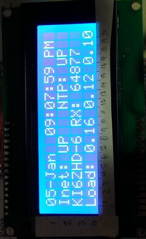
The goal of this section is to add an LCD display to the Raspberry Pi to show what's
going on with the packet station at a glance.  The current script will display the
following on the 20x4 LCD. See a section below if you have an OLED display.

    +--------------------+
    |27-Oct  08:27:31 PM |
    |Inet: UP   NTP: UP  |
    |KI6ZHD-8  RX: 12432 |
    |Load: 0.16 0.07 0.02|
    +--------------------+

There really are infinite different things that can be displayed on say a 20x4 or 16x2 LCD
display or even more on high definition OLED displays, etc.  It's all up to you but I
just wanted to display something simple, meaning ful but also readable from a distance.
Using one of these blue backlit 20x4 LCD displays is both cheap and very easy to read:

   $8.75 - Blue Serial IIC/I2C/TWI 2004 204 20X4 Character LCD Module Display For Arduino
   https://www.ebay.com/itm/321923408888

This inexpensive LCD is about the same width and hight a Raspberry Pi SBC.  It is
simply driven via a four wires (+5, GND and two I2C data connections) instead of most
high resolution LCD displays using many many GPIO pins.  This is a 5volt display but
even though the Raspberry Pi is a 3.3v device, the Rpi offers a +5v pin for the backlight
and can drive it just fine.

   NOTE:  It's important to connect LCD backlight to a +5.0v pin and not 3.3v pin. If
          you try to use the 3.3v pin, the backlight won't be bright enough to be able
          to read the text on the display


 +------------------------------------------------------------------------------------+
 | DAMAGE   On this specific (cheap) unit, the I2C to LCD piggyback / backpack board  |
 | WARNING! is soldered on at a funky angle.  Just behind the piggyback board is one  |
 | -------- of the twisted metal retainer clips to mechanically bind the LCD to the   |
 |          PCB.  Unfortunately,  if this piggy back board is pushed down too far, it |
 |          will SHORT OUT the board!!!  This has happened to me and fortunately, the |
 |          5volt USB power supply shutdown before things got too hot and nothing     |
 |          fried.  You might not be so luck so I recommend you check this!           |
 |                                                                                    |
 |          I recommnend to take a pair of needle nose plier and carefully bend this  |
 |          one twist mount back and forth until it breaks off.  Once gone, tape a    |
 |          small peice of card board down against the LCD PCB with electrical tape   |
 |          to make sure these two boards can NEVER touch!                            |
 +------------------------------------------------------------------------------------+

To get started, you first need to run the Raspberry Pi setup tool and ensure the I2C bus
is enabled:

  sudo raspi-config

     Goto :

         - Interfacing options
              - I2C        : If you have any I2C low speed devices and plan to use them, enable this

Exit the program to save the new settings.  Now shutdown the Pi before you connect
the LCD+Piggback I2C board with:

   sudo /sbin/shutdown -h now


Now unplug the power from your Rpi and wire up the LCD display to the Pi.  For me, I used:

   http://pinout.xyz/
   --
   Rpi pin                        LCD pin
   --------+---------------------+--------
      2    : +5V backlight power :   VCC
      3    :      I2C DATA       :   SDA
      5    :      I2C Clock      :   SCL
      6    :       ground        :   GND

   --

I personally also wrapped up the board in a bit of card board and tape as a form of
a crappy case just to prevent any other electical shorts, etc.  In the future, I hope
to find an inexpensive case to enclose it in.  There are also lots of 3D print designs
available on thingverse.com too.

Now power back up the Rpi with the connected display.  Once powered, the display's
backlight should light up but either two rows of blocks should show up or nothing be
on the display.  Once the Rpi is booted back up, SSH back into it and install some
key I2C packages:

   Bookworm, Bullseye, Buster (transition) and newer OSes:
      sudo apt install i2c-tools python3-smbus

   Buster, Jessie, Wheezy and older OSes:
      sudo apt install i2c-tools python-smbus


Once those tools are installed, try running the following command to see if the
I2C display is detected:

   # detect all I2C IDs on the second I2C bus (Rpi4 and newer Pi hardware):
   sudo i2cdetect -y 1

        0  1  2  3  4  5  6  7  8  9  a  b  c  d  e  f
   00:          -- -- -- -- -- -- -- -- -- -- -- -- --
   10: -- -- -- -- -- -- -- -- -- -- -- -- -- -- -- --
   20: -- -- -- -- -- -- -- -- -- -- -- -- -- -- -- --
   30: -- -- -- -- -- -- -- -- -- -- -- -- -- -- -- 3f
   40: -- -- -- -- -- -- -- -- -- -- -- -- -- -- -- --
   50: -- -- -- -- -- -- -- -- -- -- -- -- -- -- -- --
   60: -- -- -- -- -- -- -- -- -- -- -- -- -- -- -- --


As you can see here, my 20x4 LCD display has an I2C address of 0x3f. I've also seen
the 0x27 or "27" address used by some vendors.  If you see a "UU" in the address
spot where you expect your RTC address, this means that the I2C address in use
(might be a good thing.. we'll see)

Now we need to get an example program going to confirm the LCD
works ok.  I would start with this simple project found that worked for me.
There are lots of them out there though.


   NOTE: 5.0v VCC vs. 3.3v VCC on the LCD backbpack
   ------------------------------------------------
   I've seen that many programs just barely show anything on the LCD display but
   if you look *very* closely, at an angle, you'll be able to tell the display is changing
   but it's way too faint.  As I was troubleshooting this, I randomly stumbled into another
   program that would show all the text in a clear, bright fashion!  Seems this specific LCD
   seemingly has TWO brightness levels but this one program is mistakenly showing the text in
   ultra-bright mode.  It's good to know things work this way but it's the wrong function.  It
   ultimately turned out that my issue was that the LCD's VCC line (aka the backlight connection)
   was connected to the Raspberry Pi's 3.3v pin and not the +5.0v pin.  Once I made thw switch
   to use the +5.0 volt power connection, I could read all the text.


So let's get a test program:

   #This fork of another user's program works well
   #   It 100% initializes well and shows text and graphics the first time, every time
   #

   cd /tmp

   #RPi_I2C_driver.py
   wget https://raw.githubusercontent.com/emcniece/rpi-lcd/master/RPi_I2C_driver.py

      # previous broken link
      # https://gist.github.com/amateusz/fa985d170e9621e92bd5093a3826594b/raw/67b0c364da4137633c73de800fc9efa15f991173/RPi_I2C_driver.py

   #example.py
   wget https://gist.github.com/amateusz/fa985d170e9621e92bd5093a3826594b/raw/67b0c364da4137633c73de800fc9efa15f991173/examples.py


Now edit the "RPi_I2C_driver.py" and change I2C address to match your display's I2C address
(one unit was at 0x3f while another unit was at 0x27).  This script also used to support different
LCD dimensions (for me, I'm using 20,4) but that was seemingly dropped:


   vim RPi_I2C_driver.py
   --
   # LCD Address
   ADDRESS = 0x27
   --


   NOTE:  This script seems to be Python2 and has issues running without some minor changes.
          If you want to still try, create this file:


          vim examples.patch
          --
          --- examples.py	2023-10-27 18:20:48.409466199 -0700
          +++ examples-new.py	2023-10-27 18:12:43.024561606 -0700
          @@ -87,16 +87,16 @@
           # now draw cust. chars starting from col. 7 (pos. 6)

           pos = 6
          -mylcd.lcd_display_string_pos(unichr(1),1,6)
          +mylcd.lcd_display_string_pos(chr(1),1,6)
           sleep(pauza)

          -mylcd.lcd_display_string_pos(unichr(2),1,pos)
          +mylcd.lcd_display_string_pos(chr(2),1,pos)
           sleep(pauza)

          -mylcd.lcd_display_string_pos(unichr(3),1,pos)
          +mylcd.lcd_display_string_pos(chr(3),1,pos)
           sleep(pauza)

          -mylcd.lcd_display_string_pos(unichr(4),1,pos)
          +mylcd.lcd_display_string_pos(chr(4),1,pos)
           sleep(pauza)

           mylcd.lcd_display_string_pos(block,1,pos)
          @@ -105,13 +105,13 @@
           # and another one, same as above, 1 char-space to the right
           pos = pos +1 # increase column by one

          -mylcd.lcd_display_string_pos(unichr(1),1,pos)
          +mylcd.lcd_display_string_pos(chr(1),1,pos)
           sleep(pauza)
          -mylcd.lcd_display_string_pos(unichr(2),1,pos)
          +mylcd.lcd_display_string_pos(chr(2),1,pos)
           sleep(pauza)
          -mylcd.lcd_display_string_pos(unichr(3),1,pos)
          +mylcd.lcd_display_string_pos(chr(3),1,pos)
           sleep(pauza)
          -mylcd.lcd_display_string_pos(unichr(4),1,pos)
          +mylcd.lcd_display_string_pos(chr(4),1,pos)
           sleep(pauza)
           mylcd.lcd_display_string_pos(block,1,pos)
           sleep(pauza)
          @@ -121,12 +121,12 @@
           # now again load first set of custom chars - smiley
           mylcd.lcd_load_custom_chars(fontdata1)

          -mylcd.lcd_display_string_pos(unichr(0),1,9)
          -mylcd.lcd_display_string_pos(unichr(1),1,10)
          -mylcd.lcd_display_string_pos(unichr(2),1,11)
          -mylcd.lcd_display_string_pos(unichr(3),2,9)
          -mylcd.lcd_display_string_pos(unichr(4),2,10)
          -mylcd.lcd_display_string_pos(unichr(5),2,11)
          +mylcd.lcd_display_string_pos(chr(0),1,9)
          +mylcd.lcd_display_string_pos(chr(1),1,10)
          +mylcd.lcd_display_string_pos(chr(2),1,11)
          +mylcd.lcd_display_string_pos(chr(3),2,9)
          +mylcd.lcd_display_string_pos(chr(4),2,10)
          +mylcd.lcd_display_string_pos(chr(5),2,11)

           sleep(2)
           mylcd.lcd_clear()
          --


          #Now apply the patch
          #
          patch -p0 examples.py


Ok, now give the program a try:

   python examples.py


This program should do the following on the LCD:

   1. light up the backlight
   2. Show some text
   3. Show a smiley face icon
   4. Show a filling bar from the left to the right
   5. Show a smiley face icon
   6. turn the backlight off


If that worked, you're in business!  We'll use this script later so let'
s move it to a permanent location:

   sudo mv RPi_I2C_driver.py examples.py /usr/local/sbin/


  NOTE: Tuning the LCD contrast:
  ------------------------------
      If you either have a hard time reading the text on the LCD display or you can see
      ligher rectangular blocks where characters could be shown, the LCD contrast on
      the backpack needs to be turned up / down.  Take a small philips screw driver and
      on the back of the LCD I2C backpack, turn the varistor to the most readable view.


Anyway, now that things are physically setup, let's get the packet status display working
on with the LCD.  In the discussion thread at

   https://www.raspberrypi.org/forums/viewtopic.php?t=190570

There was an example program posted at https://www.dropbox.com/s/lxdprouv6i8d1re/LCD_16x2_I2C.zip?dl=0
which runs a basic clock.  Unfortunately, this code doesn't seemingly initialize the LCD
properly 100% of the time so I load each of the two above programs to get things working.
This is a total hack but it does work for now.


I then enhanced the program to include the above mentioned display items with showing:

   - The Month-Day datestamp    Local time AM/PM
   - The status of the Internet connection (pinging 8.8.8.8) and
     the status of the NTP session (do we have Internet time)
   - The current running callsign and the number of received AX25 packets
   - The system load with 1min / 5min / 15min details

You can grab a copy of my modified script here:

   cd /tmp
   wget http://www.trinityos.com/HAM/CentosDigitalModes/RPi/usr/local/sbin/lcdui-modified.py
   wget http://www.trinityos.com/HAM/CentosDigitalModes/RPi/usr/local/bin/is-internet-up.sh
   sudo mv lcdui-modified.py /usr/local/sbin/
   sudo chmod 755 is-internet-up.sh
   sudo mv is-internet-up.sh /usr/local/bin/


Next, if your LCD display is NOT at I2C address 0x37, you need to edit the file and change
this "0x37" to your address say 0x27:

   sudo vim lcdui-modified.py
   --
   device = lcd(0x3f, 1, backlight, initFlag)
   --


Ok, try running the script

   python /usr/local/sbin/lcdui-modified.py


It should look something like the following on the LCD screen:

    +--------------------+
    |27-OCt  08:27:31 PM |
    |Inet: UP   NTP: UP  |
    |KI6ZHD-8  RX: 12    |
    |Load: 0.16 0.07 0.02|
    +--------------------+


You can find other examples of LCD display programs here:

  #C and Python examples : Missing URL for libraries
  https://www.sunfounder.com/learn/sensor-kit-v2-0-for-raspberry-pi-b-plus/lesson-30-i2c-lcd1602-sensor-kit-v2-0-for-b-plus.html


If that runs well, have it start at boot up with adding the following to the /etc/rc.local file:

   sudo vim /etc/rc.local
   --
   echo -e "\nStarting up LCD on I2C address: 0x37"
   #this test script seems to initialize the LCD properly every time
   python /usr/local/sbin/examples.py
   #This is the running program but doesn't aways init properly
   python /usr/local/sbin/lcdui-modified.py &
   --
60.b. Setup a DS3231 battery backed up real time clock (RTC) and some Rpi5 RTC detail
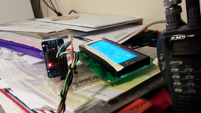
This section covers how to add a DS3231 realtime clock (RTC) to your Raspberry Pi to allow it
to automatically set the system's date/time upon initial power up.  There is also a little bit
of detail about the new Raspberry Pi 5 included RTC functionality too.

There are a lot of different RTC kits, HATs, and other solutions out there for the Raspberry Pi,
Arduino, etc. which might use the basic PCF8523 chip, the better DS1307 chip, the much better
DS3231 chip, other RTC chips, and also the new Raspberry Pi 5 RTC built-in support.  Your third
party RTC also might use a different I2C addresses than the one mentioned in this scrtion so you
might need to adapt these steps below to your specific RTC hardware.

It's also important to understand this section builds upon the I2C enablement steps previously
mentioned in the "connecting an LCD to your Rpi" section.  As such, you must least install the
key I2C programs in that previous section FIRTST before following this section.


Background:
-----------
    You might be thinking to yourself, "Why do I need an DS3231 RTC device if you already (possibly)
    have a USB-based GPS connected which can set the clock as described in a previous section?
    That's a good question so consider this:

          1. An DS3231 RTC consumes almost no power and its always running even when your Rpi is
             not powered.  It will give the Raspberry Pi system the correct date/time upon
             initial boot for accurate logging.  Using a GPS to set your system's dated/time takes
             much longer to get the date/time and then reflect in your system's logs, etc.

          2. If your setup is in a static location or have poor GPS satellite reception,
             why waste the power on a GPS receiver and worse, suffer GPS position jitter (your
             position keeps moving around).  Instead, just statically set your location in
             the APRS application

          3. Some RTC solutions like the Raspberry Pi 5 RTC also supports the ability to wake
             up your Rpi5 from a deep sleep, do some processing, and then go back into a deep
             sleep

          4. Setting up a RTC is arguably easier and cheaper

          5. Why not have both?  :-)


The specific third party DS3231 RTC unit I bought is this one:

   # NOTE: this website URL buys THREE units for a total cost of $7 including the batteries ($2.30 US/ea)!
   #       That's a great deal though these are evidently Chinese boards with a questionable sourcing
   #       of these Dallas DS3231 chips (possibly even ?counterfeit?)
   #
      http://www.ebay.com/itm/231880855190

   # In comparison, Adafruit sells a similar RTC with what should be a true Dallas part for $13.95 US
   # for just one unit which also doesn't include a battery (another $0.95).  That's 6.5x more expensive
   # but it's # probably both the better quality part and the more ethical purchase (not ripping off
   # Dallas Semiconductor)
   #
      https://www.adafruit.com/?q=DS3231


   # If you're curious to learn more about these DS3231 knockoff chips, you can read more say here:
   #
      http://dangerousprototypes.com/blog/2016/01/15/using-a-2-ds3231-rtc-at24c32-eeprom-from-ebay/


Anyway, assuming you have your third party RTC board with a battery ready to be connected to your
Raspberry Pi and you already enabled the I2C bus per the previous section for the LCD display (if not,
read up on that now and come back here), let's shutdown your Rpi to connect it:

   sudo /sbin/shutdown -h now


NOTE: For Raspberry Pi 5 owners who have connected up the small battery pack, skip down a bit
----  in this section

Now unplug the power from your Rpi and wire up the RTC.  This wiring is very similar to the
the LCD setup above but this RTC chip uses the +3.3v voltage ONLY.  I've read conflicting
information where some sites say you can power it with +5.0v as well but I don't recommend it.
I've personally have things working with the +3.3v line only.  You also might consider wiring
things up through a little Raspberry Pi breadboard like this:

   https://fe-pi.com/products/proto-z-v1

   IMPORTANT:  This specific proto board connects the three pins together just like a
               breadboard on BOTH sides of the PCB.  These are NOT just individual holes with
               solder grommets as I had expected.  I missed that and I completely screwed up
               one board and had to use an Exacto knife to cut the traces on both sides of
               the board to un-short my board!


I2C bus wiring:

   I2C buses can be wired either in a serial or parallel fashion.  In this setup, I connected
   the Raspberry Pi to a breadboard.  On the breadboard, I connected up both the RTC as well
   as connected jumper cables to the LCD display in PARALLEL.  Works well.


Here is a nice website for showing the standard and alternative Rpi header pinouts:

   http://pinout.xyz/

   Rpi physical
     pin                         RTC pin
   --------+------------------+--------
      1    :   +3.3v power    :   VCC
      3    :    I2C DATA      :   SDA
      5    :    I2C Clock     :   SCL
      6    :      ground      :   GND


Once everything is wired up, power back up the Rpi with the RTC board connected.  If you
bought the same DS3231 RTC as I did, the LED on the RTC board should light up meaning
it has +3.3v.


Once the Rpi booted back up, log in and install some key I2C packages
(if not already installed):

   #Bookworm, Bullseye, Buster (new transition) and newer distro versions:
   #
   sudo apt -y install i2c-tools python3-smbus

     or

   #Buster (old transition), Jessie, Wheezy and older distro versions:
   sudo apt install i2c-tools python-smbus


Detecting RTC modules:
----------------------
   Once those I2C tools are installed, try running the following
   command to see if the I2C-based RTC module (and maybe other
   I2C devices) are detected:

   sudo i2cdetect -y 1
   --
        0  1  2  3  4  5  6  7  8  9  a  b  c  d  e  f
   00:          -- -- -- -- -- -- -- -- -- -- -- -- --
   10: -- -- -- -- -- -- -- -- -- -- -- -- -- -- -- --
   20: -- -- -- -- -- -- -- -- -- -- -- -- -- -- -- --
   30: -- -- -- -- -- -- -- -- -- -- -- -- -- -- -- 3f
   40: -- -- -- -- -- -- -- -- -- -- -- -- -- -- -- --
   50: -- -- -- -- -- -- -- 57 -- -- -- -- -- -- -- --
   60: -- -- -- -- -- -- -- -- 68 -- -- -- -- -- -- --
   70: -- -- -- -- -- -- -- --
   --


In the above output, I see:

   0x3f : 20x4 LCD display on I2C Bus 1 - described in the previous chapter
   ----
   0x57 : DS3231 RTC's internal AT24C32 32K EEPROM (not all units have this)

   0x5f : Seems some counterfeit DS3231 RTC chips might use this address
          https://electronics.stackexchange.com/questions/397569/i2c-response-to-ghost-address-0x5f

   0x68 : DS3231 RTC time source

If you see a "UU" in the address spot where you expect to see the RTC 0x68 address, this
actually means that the RTC and it's I2C address is already in use!   That most likely
means your Raspberry Pi distro already recognized the RTC and has configured it (that's
what happened to me).  That's a good thing but to confirm that in-use point, try running:

   ls -la /dev/rtc0


If that command comes back with something like the following, your system is already up
and running (aka.. you're done!):

   crw------- 1 root root 253, 0 Dec 31  1969 /dev/rtc0

  If that DOES already show up,  also try running the following command:

     dmesg | grep rtc

  and confirm the output looks like this to confirm things are indeed setup properly:
  --
  [    9.133480] rtc-ds1307 1-0068: SET TIME!
  [    9.137606] rtc-ds1307 1-0068: rtc core: registered ds3231 as rtc0
  --


Raspberry Pi 5 with RTC battery users:
--------------------------------------
   Run the command "dmesg -T | grep rpi-rtc" and if you see the details below, your native
   RTC is working!
      --
      [Mon Feb  5 18:57:42 2024] rpi-rtc soc:rpi_rtc: registered as rtc0
      [Mon Feb  5 18:57:42 2024] rpi-rtc soc:rpi_rtc: setting system clock to 2024-02-06T02:57:42 UTC (1707188262)
      --

   The Rpi5 RTC solution can use a rechargable battery instead of th more common non-rechargable battery
   like a CR2032 which is commonly found on most third-party RTC solutions.  Per the Official Raspberry documentation,
   this do NOT recommend to use non-recharable battery as their RTC solution consumes more power than say a DS3231.
   Ok, that's not great but at least making this recharable gives you options.  If you take that option, makes it
   Ironically, this recharging is NOT enabled by default so it needs to be enabled.  You can see this by running the
   command:

      cat /sys/devices/platform/soc/soc\:rpi_rtc/rtc/rtc0/charging_voltage
      --
      0
      --

   To enable this, append the following line to part of the config file where other "dtparm" items are:

      sudo vim /boot/firmware/config.txt
      --
      dtparam=rtc_bbat_vchg=3000000
      --

   Now reboot your Rpi5 and again check out the dmesg command output as recommended above:

      dmesg -T | grep rtc
      --
      [Wed Feb 14 12:45:49 2024] rpi-rtc soc:rpi_rtc: trickle charging enabled at 3000000uV
      [Wed Feb 14 12:45:49 2024] rpi-rtc soc:rpi_rtc: registered as rtc0
      [Wed Feb 14 12:45:49 2024] rpi-rtc soc:rpi_rtc: setting system clock to 2024-02-14T20:45:49 UTC (1707943549)
      --

      Confirm that output above shows "trickle charging enabled at 3000000uV" aka 3 volts.


   More details can be shared here but until I do, you can read more here:

      https://www.raspberrypi.com/documentation/computers/raspberry-pi-5.html#real-time-clock-rtc


Back to the third-party RTC solution:

  IMPORTANT:   Now, things look good from the above commands and even work but if you look
  ----------   closely, does your output show the "ds3231" or does it show "ds1307" instead
               like this output below?
    --
    [    9.049339] rtc-ds1307 1-0068: rtc core: registered ds1307 as rtc0
    [    9.049408] rtc-ds1307 1-0068: 56 bytes nvram
    --

    If your ouput also has the INCORRECT string "registered ds1307" text, maybe your RTC chip
    is really a ds1307 chip or it was incorrectly recognized by the OS (common occurance).  The
    behavior for this output seems to be inconsistent but it's actually the ds1307 kernel module
    that supports BOTH the ds1307 and ds3231 chips.  If you tell the OS to specifically load the
    ds3231 option, it can give you additional features.  Visually inspect your RTC chip very
    carefully and if you believe you really have a ds3231 chip, you'll need to update your
    /boot/config.txt file as instructed below to gain access to some of this chip's
    advanced features like temperature sensors, flash ROM, etc.


  If things do look good, you're not 100% done.  You need to skip down to the end of this section and
  program the RTC to have the correct date/time.


Configuring your third party I2C RTC if not recognized
------------------------------------------------------
If the "ls -la /dev/rtc0" command comes back with a:

   ls: cannot access '/dev/rtc0': No such file or directory


This probably just means your specific RTC board might be at different I2C address.  No big deal.
All you'll need to do is research what I2C addresses your specific RTC board will show up as
from the seller.  If you don't see ANYTHING in the above "i2cdetect" command output, you need to
make sure:

   -  the I2C bus is turned on in the raspi-config tool (see Section #4 of this doc)

   -  check your wiring from the Rpi to the RTC module, etc.  You might also try running the i2cdetect
      command on the other I2C bus (try I2C bus 0)


Assuming your RTC was NOT recognized (not showing as "UU" above), let's give it a temporary test by
running the following commands to get the kernel module to load and connect to the device on
I2C bus 1 (Raspberry Pi v1 owners will need to use bus 0 instead):

   # You must use su command here and NOT sudo to run the entire command as it's passing multiple
   # parameters
   #
   #  Change the "0x68" to match the I2C ID of your specific RTC
   #
   sudo su
   echo ds3231 0x68 > /sys/class/i2c-adapter/i2c-1/new_device
   exit


If you get an error like "bash: echo: write error: Invalid argument", your RTC chip
is probably already being used (shown as "UU").  Now check the output of the I2C command again:

   sudo i2cdetect -y 1

Does the 0x68 address now show as "UU" in it's place like this:
   --
        0  1  2  3  4  5  6  7  8  9  a  b  c  d  e  f
   00:                         -- -- -- -- -- -- -- --
   10: -- -- -- -- -- -- -- -- -- -- -- -- -- -- -- --
   20: -- -- -- -- -- -- -- -- -- -- -- -- -- -- -- --
   30: -- -- -- -- -- -- -- -- -- -- -- -- 3c -- -- --
   40: -- -- -- -- -- -- -- -- -- -- -- -- -- -- -- --
   50: -- -- -- -- -- -- -- 57 -- -- -- -- -- -- -- --
   60: -- -- -- -- -- -- -- -- UU -- -- -- -- -- -- --
   70: -- -- -- -- -- -- -- --
   --


Hopefully it now shows "UU" and that means the RTC is now (temporarily) in use!  That also
means Linux loaded the DS1307 / DS3231 kernel module.  Confirm the kernel module is loaded
by running:

   lsmod | grep ds
   --
   rtc_ds1307             13908  0
   hwmon                  10552  1 rtc_ds1
   --


Also make sure the RTC device was created as well:

   ls -la /dev/rtc*
   --
   lrwxrwxrwx 1 root root      4 Nov 20 17:05 /dev/rtc -> rtc0
   crw------- 1 root root 253, 0 Nov 20 17:05 /dev/rtc
   --


Assuming you DO see the "UU" now, let's now see if you can read the time from it:

   #Simply READ from the chip
   sudo hwclock -r -f /dev/rtc0
   --
   1999-12-31 23:44:08.906751-0800
   --


If you see some of that... even if the date / time is wrong.. that's still awesome as that
means the RTC is working and can be accessed.  The WRONG date and time just means it's brand
new and it might not have ever been programmed.  Assuming you Raspberry Pi has already
configured to get it's time by being an NTP client per the previous section in this document
(highly recommend and also see WHY I' m using ntpdate vs say other tools as well),
configuring the RTC date/time will be easy.

You should confirm you DO have good NTP lock via some remote time servers.  Here is what
I see for my system.  The remote host with a "*" is the current system used for time:

   # If you're NOT using ntpd per the previous section (needed for use with getting the
   # date/time from a GPS receiver, let's look at it via Systemd's solution:
   #
   timedatectl
     --
                    Local time: Fri 2023-10-27 17:32:42 PDT
                Universal time: Sat 2023-10-28 00:32:42 UTC
                      RTC time: Sat 2023-10-28 00:32:42
                     Time zone: US/Pacific (PDT, -0700)
     System clock synchronized: yes
                   NTP service: active    <----------------------------------------
               RTC in local TZ: no
     --

   If you see something like that above, that means you have a valid NTP connection and accurate time.


   # Alternatively, If you enabled ntpd per the previous section (needed for use with getting the
   # date/time from a GPS receiver, let's look at the NTP details via the command "ntpq":
   #
   ntpq -c peers
   --
        remote           refid      st t when poll reach   delay   offset  jitter
   ==============================================================================
    SHM(0)          .GPS.           15 l    -   16    0    0.000    0.000   0.000
    0.debian.pool.n .POOL.          16 p    -   64    0    0.000    0.000   0.001
    1.debian.pool.n .POOL.          16 p    -   64    0    0.000    0.000   0.001
    2.debian.pool.n .POOL.          16 p    -   64    0    0.000    0.000   0.001
    3.debian.pool.n .POOL.          16 p    -   64    0    0.000    0.000   0.001
   +eterna.binary.n 204.9.54.119     2 u  707 1024  377   52.846    2.335 143.338
   +time.tritn.com  63.145.169.3     2 u  149 1024  377   26.745    0.763   6.440
   +christensenplac 200.98.196.212   2 u  147 1024  373   87.077    2.070   9.090
   -40.85.153.82    45.76.244.193    3 u   62 1024  377   16.602    2.725  22.823
   *rolex.netservic .kPPS.           1 u  825 1024  177   82.314   -3.493  11.500  <-------
   --


Ok, assuming you have a good date/time, let's update the DS3231 RTC's clock.  It's as
easy as running the previous command but now we're going to WRITE to it.  Running this
command won't give any output as it completes.  The second command here will then read
from the chip and confirm the correct date/time:

   sudo hwclock -w -f /dev/rtc0
   #no output given


Now re-read the date/time from the RTC and make sure it has the right time and date:

   sudo hwclock -r -f /dev/rtc0
   --
   2023-10-27 17:35:12.789499-07:00
   --


Great!  Now you've been able to set and read back the correct time! Now all you have to do
is enable the RTC kernel module to load up at boot time.  To do this, edit the /boot/config.txt
file, find the line that has the "dtoverlay" line  and make the change.

  Add these two lines after the last line that has "dtoverlay" in it:

      NOTE: create a new line that reads the following (btw, you CAN have multiple active
            "dtoverlay" lines in this file

   #Bookworm and later OSes:
   sudo vi /boot/firmware/config.txt

   #Bullseye and earlier OSes:
   sudo vi /boot/config.txt

     --
     #Enable RTC
     dtoverlay=i2c-rtc,ds3231
     --


Next, it's recommended to remove the stock Raspberry Pi "fake" hardware clock package if
you intend to always keep this RTC module connected to your Rpi.  You can do that with:

   sudo apt remove fake-hwclock


Next up, for most Raspberry Pi OS (Bookworm, Bullseye, Buster and other versions that use
SystemD, you need to edit one more file and COMMENT out a few lines:

   sudo vim /lib/udev/hwclock-set

         Find the following lines (usually starting at line 7):
         --
         if [ -e /run/systemd/system ] ; then
             exit 0
         fi
         --

      and add # characters on those three lines comment the lines out so they look like

         --
         #if [ -e /run/systemd/system ] ; then
         #    exit 0
         #fi
         --

That should be it!  To test everything, go ahead and reboot your Raspberry Pi with:

   sudo /sbin/shutdown -r now


Once the RPi reboots, log back into the Rpi and try running:

   ls -la /dev/rtc*

      Confirm the /dev/rtc device is listed:
      --
      lrwxrwxrwx 1 root root      4 Nov 20 17:05 /dev/rtc -> rtc0
      crw------- 1 root root 253, 0 Nov 20 17:05 /dev/rtc
      --


   dmesg -T | grep rtc-

      You should see the RTC being recognized:

      --
      [Fri Oct 27 17:41:42 2023] rtc-ds1307 1-0068: registered as rtc0
      --


BONUS:  A built in temperature sensor on DS3231 RTCs!
-----------------------------------------------------
The DS3231 RTC chip (not the DS1307 chip) also includes a highly accurate temperature sensor
which is included for it to keep far more accurate time compared to NON-temperature compensated
RTCs.  Assuming you configured and rebooted your Rpi to use the DS3231 chip vs the basic ds1307
non-temperature compensated module, you can read the temperature from the DS3231 RTC.

Use this command to determine which device will report the temperature sensor:

   find /sys/devices/ | grep 0068 | grep temp1_input
   --
   /sys/devices/platform/soc/20804000.i2c/i2c-1/1-0068/hwmon/hwmon2/temp1_input
   --

Assuming you got a response similar to above, try cat'ing that file to get a temperature
reading in Celsius:

   #Use a little embedded commands here to do two things in one line
   #
   cat `find /sys/devices/ | grep 0068 | grep temp1_input`
   --
   23250
   --


If the above commands didn't work, read below.  For a working example, I used the following command
but you might need to "cat" the output of what was found above:

   Rpi3:
   ----
   cat /sys/devices/platform/soc/3f804000.i2c/i2c-1/1-0068/hwmon/hwmon0/temp1_input

   23250
   --

   Rpi Zero-W
   --
   cat /sys/devices/platform/soc/20804000.i2c/i2c-1/1-0068/hwmon/hwmon1/temp1_input

   23250
   --


That output is showing it's 23.250 degrees Celsius (73.850 degrees Fahrenheit).  If you have the
"bc" package installed, you can convert to Fahrenheit with this one line command:

   #Update this RTCTEMP variable to use your specific valid device as described above
   #
   RTCTEMP="/sys/devices/platform/soc/20804000.i2c/i2c-1/1-0068/hwmon/hwmon2/temp1_input"
   echo "scale=2; (`cat $RTCTEMP` / 1000.0) * (9/5) + 32" | bc -l


   The output of those two lines should look like something like:
   --
   76.10
   --


If you get a response but the temp seems too high, check the placement of the RTC board.
Is it close to a heat generator like the RPI's CPU?  If so, try moving it to a different
place away from any heat generators.  Maybe you are using a case with your Raspberry Pi
but it doesn't have any ventalation holes, doesn't have a fan, etc?


If you get an error polling for the temperature, it's possible that one of a few things happened:

  1. You didn't enter in the right I2C address in the "cat" command.  Try finding the right address
     with the following command:

          sudo find /sys/devices/ | grep 0068 | grep temp1_input

     On some systems, I got the response:

          /sys/devices/platform/soc/20804000.i2c/i2c-1/1-0068/hwmon/hwmon0/temp1_input

     that means I need to give the command:

         cat /sys/devices/platform/soc/20804000.i2c/i2c-1/1-0068/hwmon/hwmon0/temp1_input


  2. You forgot to reboot your system to use the ds3231 personality of the kernel module

  3. Your DS3231 is a counterfeit chip (very common when buying cheap Ebay / AliExpress / etc RTC
     devices.  Please read the URLs in the beginning of this section to learn more on what you get
     when you pay very little

  4.  The OS has auto-configured your RTC setup yet is loading the WRONG RTC driver.  Check your
      config.txt file as mentioned above and on the "dtoverlay" line, make sure it reads:

         dtoverlay=i2c-rtc,ds3231

      NOT

         dtoverlay=i2c-rtc,ds1307

      If you had to change this, reboot your Raspberry Pi for the changes to go into effect.
60.e. Infrared (IR) transmitter and 8 channel light sensor

TBD: Setting up an InfraRed IR TX/RX Raspberry HATT board with a secondary DIY light meter sensor

  I have a complete setup working using the following HAT board:

     https://raspberrypiwiki.com/index.php/Raspberry_Pi_IR_Control_Expansion_Board

        - This board DOES require custom LIRC packages to be compiled to be compatible due to known
          kernel issues


  I also have developed my own DIY hat design which includes a SPI-connected MCP3008 ADC with a light
  sensor to confirm that the remote device (a Finnex fishtank light) has actually turned on/off.  If
  it didn't change, there are scripts that do automatic retries, etc.

I will slowly work on adding these IR/ADC HAT and package creation instructions to this document.
Until then, if you would like to get a copy of my notes to get started, email me.
[Chapter Gap]
70. Stuff that still needs to be added or updated
OBSOLETE:  This code has been unmaintained for years now and though a very slick tool, it probably
           no longer works

N7NIX Dan tracker
-----------------
Need to consider the integration of the DanTracker document at:

    hampacket2:/usr/src/archive/RPi/n7nix-udrtracker-install.txt

into this doc.  The challenge here is that this valuable program's source code
has long been abandoned.

   DanTracker currently does NOT support gpsd and
   - only supports GPSes on /dev/ttyUSB*
   - only supports NEMA GPSes
   - does not initialize SiRF GPSes to send NEMA
   - does support for setting the time via GPS once a day

  Concerns:
  - even if I disable DanTracker GPS and gpsd and just run:
    cat /dev/ttyUSB0 > /dev/null
    the impact hits direwolf where it under-samples and then fails to do decodes:

          Past 100 seconds, 4275495 audio samples, 0 errors.


  #Update the config - Dantracker currently ONLY supports devices like ttyUSB0
  # (not /dev/serial/by-id/usb-Prolific_Technology_Inc._USB-Serial_Controller_D-if00-port0 )

  vi /etc/tracker/aprs_tracker.ini
  --
  port = /dev/ttyUSB0
  --


  #You have to get the GPS running in NEMA mode first
  sudo gpsd -N -D3 -n /dev/ttyUSB0

  /etc/tracker/tracker-up


  To view the current system, use:

     http://192.168.0.10:8080/tracker.html
         or
     http://192.168.0.10:8081/spy.html


  # Is this needed for N7NIX DanTracker?

  /etc/init.d/prepare-dirs
  --
  #!/bin/bash
  #
  ### BEGIN INIT INFO
  # Provides:          prepare-dirs
  # Default-Start:     2 3 4 5
  # Default-Stop:      0 1 6
  # Required-Start:
  # Required-Stop:
  # Short-Description: Create /var/log/nginx directory on tmpfs at startup
  # Description:       Create /var/log/nginx directory on tmpfs at startup
  ### END INIT INFO

  DIR=/var/log/lighttp

  #
  # main()
  #
  case "${1:-''}" in
    start)
      # create the /var/log/nginx needed by webserver
      if [ ! -d ${DIR} ]; then
        mkdir ${DIR}
        chmod 755 ${DIR}
      fi
      ;;
    stop)
      ;;
    restart)
     ;;
    reload|force-reload)
     ;;
    status)
     ;;
    *)
     echo "Usage: $SELF start"
     exit 1
     ;;
  esac
  --

  chmod 755 /etc/init.d/prepare-dirs
  update-rc.d prepare-dirs defaults 01 99


  # ------------------------------------------------------------------------
  Check out http://dantracker.tk/tracker.html for more RPi optimizations, etc
  # ------------------------------------------------------------------------


# This note is only relevant for F6BVP's based Rpi image (obsolete)

   You can update the various F6BVP code, AX25 stack, etc. from the included scripts:

   cd /usr/local/src/
      Instax25.new
      updAX25
      updfbb
      updfpac


#Other ideas.. make the whole SD card read only

  https://hallard.me/raspberry-pi-read-only/


# Maybe install Xastir - old though - currently at 2.0.4
  apt install Xastir


# ---------------------------------------------------------------
# Possibly Deprecated
# ---------------------------------------------------------------


# ---------------------------------------------------------------
?Still needed for Jessie?

# /var/log items go into the tmpfs ram drive anyway

Suppress 1000s of cron lines like the following in /var/log/auth.log
#
#   Jan 30 18:49:01 ota3 CRON[14054]: pam_unix(cron:session): session opened for user zzz by (uid=0)
#   Jan 30 18:49:03 ota3 CRON[13055]: pam_unix(cron:session): session closed for user root

edit /etc/pam.d/common-session-noninteractive

At the end of the file, find the line:

   session required pam_unix.so

and now add the following line ABOVE it

   session [success=1 default=ignore] pam_succeed_if.so service in cron quiet use_uid
80. Todo
03/27/24 - remove duplicate disabling of say Avahi, etc.

03/17/22 - Move logrotation to an eariler section - ideally at the same time as enabling
           LOG ram drive
90. Special Topics
These sub-sections are used to keep various misc. projects I've completed with the Raspberry Pi
but haven't found a better place in this document (for now):
90.a - Use a Coastal Chipworks TNC-Pi on your Raspberry Pi
-------------------------------------------------------------------------
This section has not been been validated for Raspberry Pi OS Bookworm yet
  though it should work
-------------------------------------------------------------------------

The above mentioned /etc/ax25/ax25-up.new script DOES have support for the TNC-Pi.  All you need
to do is edit the script to use the TNC-Pi routines vs. the Direwolf ones.  It should just work.


   1. - On the TNC-Pi board, does it have Jumpers JP2 and JP3 right next to the Rpi GPIO pin header?
        If so, they both MUST be in-place to communicate to the TNC-Pi to change it's settings (for
        either serial OR I2C mode).  They must remain there if the TNC-Pi is to use the serial port
        interface or REMOVED if you're going to use the TNC-Pi via the I2C bus

   2. - If you have a Raspberry Pi v3, you MUST make two changes to the Pi hardware configurationup to
        swap the on-board SBC hardware serial port to be connected to the GPIO pins instead of the default
        to be connected to the on-board Bluetooth controller (this is required when using the hardware
        TNC-PI HATT board either in serial or I2C mode)

           Edit the /boot/config.txt file and add these two lines:

              dtoverlay=pi3-miniuart-bt
              core_freq=250

           You can read more about these changes here:
           http://raspberrypi.stackexchange.com/questions/45570/how-do-i-make-serial-work-on-the-raspberry-pi3

   3. - You need to enable the serial port on the Rpi with the following steps but unfortunately,
        this approach both enables the serial port AND the serial console support at the same time.  We
        don't want the serial console support so that part has to be undone:

           sudo raspi-config --> Interface Options --> Serial Port --> YES --> Ok --> Finish

           On older Raspbian releases, you would find this in :
              sudo raspi-config --> Advanced Options --> Serial --> YES --> Ok --> Finish

        Select YES to reboot your Raspberry pi


   4. - Make sure the serial console is not enabled

      Look at the /boot/cmdline.txt file and Look for the string:

         console=serial0,115200

      If you see it, you'll need to edit the file with sudo rights, remove that portion of text, save
      the file and get ready to reboot the Rpi


   5. - Now reboot your rpi with:

      sudo /sbin/shutdown -r now


   6. - Make sure the /dev/ttyAMA0 serial port is recognized

      ls -la /dev | grep AMA
      --
      lrwxrwxrwx  1 root root           7 Nov  6 09:44 serial0 -> ttyAMA0
      crw-rw----  1 root dialout 204,  64 Nov  6 09:44 ttyAMA0
      --

      If it's NOT seen, you need to try using the "sudo raspi-config" step again


   7. - Make sure there aren't any console sessions configured to use /dev/ttyAMA0

      ps aux | grep getty

      If you see something like the following, you need to fix this
         --
         root      1077  0.8  0.1   4112  1764 ttyAMA0  Ss+  08:24   0:18 /sbin/agetty --keep-baud 115200 38400 9600 ttyAMA0 vt102
         --

      Disable the getty running on /dev/ttyAMA0 permanently the Jessie / SystemD way with:

         sudo systemctl stop serial-getty@ttyAMA0.service
         sudo systemctl disable serial-getty@ttyAMA0.service


   8. - Make sure there aren't any AX25 interfaces already loaded

      ifconfig | grep ax

          If there are, use the command "sudo ifconfig ax0 down" to shut them down


   9. - Make sure there aren't any KISS applications already running:

      ps aux | grep kiss

      Use the command "sudo killall kissattach" to kill any running kissattach commands (also removes any mkiss commands too)


   10. - Download the newest TNC-Pi get/set tools

      sudo mkdir /usr/src/pitncgetset
      cd /usr/src/pitncgetset

      # Get the newest John Wiseman G8BPQ code - current as of 08/30/18
      #
      wget http://www.cantab.net/users/john.wiseman/Downloads/PITNCParamsApr18.zip
      wget http://www.cantab.net/users/john.wiseman/Downloads/i2ckiss.zip

        # If the above links don't work, try looking for a different version of
        # the "PITNCParams" filename.  You can also try downloading it at the following
        # URL but that link doesn't always seem have the newest available code:

             http://www.tnc-x.com/pitnc.zip
               and
             http://www.tnc-x.com/i2ckiss.zip

               or another alternative: https://dl.dropboxusercontent.com/u/31910649/i2ckiss


   11. - Uncompress and make sure the pitncgetset binaries are executable

      #Uncompress the archive
      sudo unzip pitncgetset.zip

      chmod 750 pitnc_setparams pitnc_getparams


   12. - Check the /dev/ttyAMA0 serial port to make sure it's ok.  Disconnect the DB9 connection going from the TNC-Pi
         to your radio.  Now run the following command (you can use control-C to stop it) and you should see NOTHING.
         If you see garbage on the screen (something like the following):

            sudo cat /dev/ttyAMA0
            ����������������������������������������������������������������

         That's bad.  I recommend to shut down your TNC-Pi with "sudo /sbin/shutdown -h now", wait to see the green
         power LED blink 7 times.  Now REMOVE the power connection from the Raspberry Pi for 30 seconds and then
         reconnect power.  Again try the above command and make sure NO garbage or any out text output is coming


   13. - Try running the pitnc_getparams program:

         - If running on a TNC-Pi v1 board:

            ./pitnc_getparams 0 0

         - if running on a TNC-Pi v2 board:

            ./pitnc_getparams 1 0


      You should see something like:

         Using Serial port /dev/ttyAMA0

            PIC Software Version           0
         01 TXDelay - Zero means use ADC  25
         02 Persistance                  250
         03 Slottime (in 10 mS)            6
         04 TXTail                         2
         05 Full Duplex - Not used         0
         06 Our Channel (Hex)             00
         07 I2C Address (0 = async) Hex   00
            ADC Value                     30
         8 0 19 fa 6 2 0 0 0 1e f1 c0 sum 0


   14. - Making changes to the TNC-Pi via I2C

      - After making any changes to the TNC-Pi's register, you need to reboot the unit.  To do so, run the
        I2C command:

           ./pitnc_getparams 15 2


   If you want to try to use the TNC-Pi in I2C mode (frees up the onboard /dev/ttyAMA0 serial port),
   here are some additional things to check:

     14.a - You will need to change the "I2C address" using the above commands to enable I2C mode, power down the
            Rpi and take off the TNC-PI JP2 and JP3 jumpers (if you have an older TNC-Pi board)


     14.b - see if the I2C drivers are installed:

        lsmod | grep i2c
        --
        i2c_bcm2708             4834  0
        i2c_dev                 5859  0
        --

        Both entries MUST be there


     14.c - make sure the i2ctools are installed

          sudo apt install i2c-tools


     14.d - Make sure the I2C bus can be found

         make sure the you see bus #1 (should show something like: i2c-1   i2c   3f804000.i2c   I2C adapter)

            sudo i2cdetect -l


     14.e  - See if you can see the TNC-Pi in I2C mode on address 15:

        --
        sudo i2cdetect 1

        WARNING! This program can confuse your I2C bus, cause data loss and worse!
        I will probe file /dev/i2c-1.
        I will probe address range 0x03-0x77.
        Continue? [Y/n]
             0  1  2  3  4  5  6  7  8  9  a  b  c  d  e  f
        00:          -- -- -- -- -- -- -- -- -- -- -- -- --
        10: -- -- -- -- -- 15 -- -- -- -- -- -- -- -- -- --
        20: -- -- -- -- -- -- -- -- -- -- -- -- -- -- -- --
        30: -- -- -- -- -- -- -- -- -- -- -- -- -- -- -- --
        40: -- -- -- -- -- -- -- -- -- -- -- -- -- -- -- --
        50: -- -- -- -- -- -- -- -- -- -- -- -- -- -- -- --
        60: -- -- -- -- -- -- -- -- -- -- -- -- -- -- -- --
        70: -- -- -- -- -- -- -- --
        --

        The output above shows NOTHING which means it's not correct.

           Troubleshooting items to be added


     14.f - Enable I2Ckiss

          Assuming you want to use the TNC-Pi in I2C mode with the Linux AX.25 stack, you would
          then run the command:

             i2ckiss 1 15 vhfdrop 10.0.0.2


     The rest of configuring the AX.25 stack is configured in the above mentioned /etc/ax25/ax25-up.new
     script.  That script DOES support the TNC-Pi setup with some simple changes.  Read and edit the
     script to suit your needs.


     Ps.  Here is an older thread will take you through a way to get things working via the I2C bus
          and not the serial port which might get you going:

          https://groups.yahoo.com/neo/groups/Raspberry_Pi_4-Ham_RADIO/conversations/topics/4755
90.b - Setup a ssd1306 I2C-based 128x64 OLED display
This section quickly covers the setup and operation of a ssd1306 20x4 character / 128x64 pixel
I2C-connected OLED display.  I find having a display directly connected to the Rpi is useful
to quickly understand how the Pi is running.  The 20x4 LCD display mentioned in a previous section
of this doc is easier to read due to their large and bright characters from a distance but can be
rather bright in a dark room (it's backlight).  These little OLED displays a much smaller and
dimmer which you might prefer.  These OLED displays come in many sizes from 0.96" (diagonal), 1.3",
and 2.42" and come in text colors of white (most common), green, blue, and yellow but for some
reason, all display sizes offer the same resolution.  Following this section and it's recommended
Python API, you will effectively get a 20x4 text display though it can also display graphics, do
scrolling of text, etc.  This example Python3 script will display the following on the OLED display:

    +--------------------+
    |IP: xxx.xxx.xxx.xxx |  <--- x is your Pi's IP address
    |CPU: x.xxLA yy.y'C  |  <--- x is your Pi's 1min CPU load average; y is the SOC temperature
    |Mem: xxx/yyyMB zz.z |  <--- z is percentage memory utilized
    |Disk: x/yyGB z%     |  <--- Z is percentage storage utilized
    +--------------------+

NOTE: I would say that the 0.96" OLED display isn't super bright.  If you want to try to make
      it brighter (might damage the display), read this article to swap out a surface mount
      resistor: https://forums.adafruit.com/viewtopic.php?p=573606#p573606


This section is based on the fine work posted at:

   https://www.the-diy-life.com/add-an-oled-stats-display-to-raspberry-pi-os-bullseye/


but.. the above URL gives instructions are OLD and need to be modernized as it will no longer
work with the new Python3 "externally managed" chroot system found in modern OSes like Raspberry
Pi OS Bookworm.

Here are the other assumptions made for this section:

  - You have a ssd1306 OLED display is at 0x3C hex

  - This section assumes you are running Raspberry Pi OS Bookworm

  - This section assumes you already enabled and installed the basic I2C tools as covered in
    the real-time clock RTC or 20x4 LCD display sections


Ok, let's get down to it:

  - Go to our build areas
       cd /usr/src/archive/Rpi-scratch/
       mkdir ssd1306
       cd ssd1306

  - Install the Python pip library tool and required dependencies:
       #
       sudo apt -y install python3-pip


  - Install the python3 setup tools
       #
       #NEW way
       sudo apt -y install python3-setuptools

          #OLD way
          pip3 install --upgrade setuptools


  - Disable Bookworm's insistance in using the new virtual environments system
       #
       sudo mv /usr/lib/python3.11/EXTERNALLY-MANAGED /usr/lib/python3.11/EXTERNALLY-MANAGED.disabled


  - Install the Adafruit display library
       #
       #NEW way
       /home/$USER/local/lib/python3.11/bin/python3 /home/$USER/local/lib/python3.11/bin/pip3 install --upgrade adafruit-python-shell

       #OLD way
       pip3 install --upgrade adafruit-python-shell


  - Download the Adafruit setup python script
       #
       wget https://raw.githubusercontent.com/adafruit/Raspberry-Pi-Installer-Scripts/master/raspi-blinka.py


  - Run the Adafruit setup python script :: This will install a LOT of pip3 modules : please be patient
       #
       #NEW way
       sudo /home/$USER/local/lib/python3.11/bin/python3 raspi-blinka.py

          #OLD way
          sudo python3 raspi-blinka.py

       ---> Once prompted, type in Y to reboot the Pi


  - Log back into your Pi once it finishes rebooting


  - Install the Adafruid CircuitPython module for the ssd1306 display :: This will install a LOT of pip3 modules : please be patient
       #
       #NEW way
       /home/$USER/local/lib/python3.11/bin/python3 /home/$USER/local/lib/python3.11/bin/pip3 install adafruit-circuitpython-ssd1306

          #OLD way
          pip3 install adafruit-circuitpython-ssd1306


  - Install the Python3 pillow library for graphic support
       #
       #NEW way
       /home/$USER/local/lib/python3.11/bin/python3 /home/$USER/local/lib/python3.11/bin/pip3 install pillow

          #Old way
          pip3 install python3-pil


  - Install an example python script that displays basic Rasberry Pi stats on the OLED display
       #
       cd /usr/src/archive/Rpi-scratch/ssd1306
       git clone https://github.com/mklements/OLED_Stats.git
       cd OLED_Stats

       #NEW way
       /home/$USER/local/lib/python3.11/bin/python3 stats.py

          #OLD way
          python3 stats.py


  - The OLED display should light up and show:

       - IP address: cycles between IPv4 and IPv6 addresses
       - CPU load (in percentage) and temperature (C)
       - RAM used / RAM available (MB) and percentage used
       - Storage used / available (GB) and percentage used


  - Start the display up at boot: add the following line to your personal cron (this is not the root user cron)
    #
    crontab -e

       - Select your preferred editor (I generally recommend Vim)

       - Add the following line at the end of the file
         --
         @reboot cd /usr/src/archive/Rpi-scratch/ssd1306/OLED_Stats; /home/$LOGNAME/local/lib/python3.11/bin/python3 stats.py &
         --

  - Reboot the Rpi to ensure the display comes up as expected

     - sudo /sbin/shutdown -r now

     - When the pi is rebooting, the display will still display the old information and won't
       be updating.  When the script restarts, should temporarily go off

     - The display should eventually start refreshing with current details


  - Run a quick 60 second CPU stress test to show the load and temp numbers show on the display.
    Run the following command:

     #For 4 core Rpis like Rpi5, 4, CM4, 400, 3+, Zero2 W, 3, CM3, 2
     stress --cpu 20 --io 20 --vm 6 --vm-bytes 25M --timeout 60s

     #For 1 core Rpis like Rpi0, 0w, 1, 1+
     stress --cpu 5 --io 20 --vm 6 --vm-bytes 25M --timeout 60s
90.c - Setup lmsensors to monitor more of the hardware
The /usr/local/bin/review-rpi-cpu.sh script mentioned in a section above provides some good
detail about the host but tools like lm-sensors can get even more details on various aspects
of the host.  The main benefit of installing lm-sensors is to add various environmental reports
to the nightly logwatch report.

  NOTE: lm-sensors does work on the various Raspberry Pi hardware models but it seems there hasn't
        been any new development to the lm-sensors project since 2019.  Worse, it seems the main
        developer resigned back in 2007:

           https://lwn.net/Articles/229996/
           https://github.com/lm-sensors/lm-sensors/issues/3


To install lm-sensors, do the following:

   # Install it from the debian repos
     sudo apt install lm-sensors

Now run the configuration wizard to search for all supported sensors

     sudo sensors-detect

     #Accept the default YES to look for all possible sensors


Now configured, you can run the "sensors" command to see what is all is available to you.
Here is an example from a Raspberry Pi 5:

   sensors
   --
   $ sudo sensors
   rpi_volt-isa-0000
   Adapter: ISA adapter
   in0:              N/A    <-------- Ignore this

   cpu_thermal-virtual-0
   Adapter: Virtual device
   temp1:        +49.6°C    <-------- This is probably the SOC CPU temp

   rp1_adc-isa-0000
   Adapter: ISA adapter
   in1:           1.48 V    <-------- Various voltages from the Rpi5 PMIC
   in2:           2.55 V    <-------- Various voltages from the Rpi5 PMIC
   in3:           1.41 V    <-------- Various voltages from the Rpi5 PMIC
   in4:           1.40 V    <-------- Various voltages from the Rpi5 PMIC
   temp1:        +56.6°C    <-------- This is probably the GPU temp

   pwmfan-isa-0000
   Adapter: ISA adapter
   fan1:        2961 RPM    <-------- Raspberry Pi Active Cooler fan RPM
   --
90.d - Send a nightly graphic of the temperatures of the Rpi SOC and RTC sensor
Want to get a plot of your Raspberry Pi's SOC and RTC temps sent to you daily?  Ok, then
follow these steps:

   +------------------------------------------------------------------------------------------+
   | NOTE:  This section assumes you enabled the postfix email system as part of the logwatch |
   |        section of this doc.  If you also want the RTC temp plots, you need to follow the |
   |        realtime clock section of this doc.                                               |
   +------------------------------------------------------------------------------------------+

   cd /tmp
   wget http://www.trinityos.com/HAM/CentosDigitalModes/RPi/usr/local/bin/monitor-rpi-temp.sh
   wget http://www.trinityos.com/HAM/CentosDigitalModes/RPi/usr/local/bin/generate-cputemp-graph.sh
   chmod 755 monitor-rpi-temp.sh generate-cputemp-graph.sh
   sudo mv monitor-rpi-temp.sh generate-cputemp-graph.sh /usr/local/bin


TBD: The foundation is present to support RTC temp plotting but it's not complete just yet


Next, you need to install gnuplot (which brings in a LOT of other Linux packages to support
boatloads of other output formats), s-nail to send emails with attachments, and the bc calculation
tool:

   sudo apt install gnuplot s-nail bc


If you have a RTC installed with a supported on-board temperature sensor, you need to update
the monitor-rpi-temp.sh script with the correct sensor path.  To do that, find the path with
the following command and your output might be different depending on your OS version, model
of your raspberry pi, etc:

   find /sys/devices/platform/soc | grep temp1_input
      --
      /sys/devices/platform/soc/20804000.i2c/i2c-1/1-0068/hwmon/hwmon2/temp1_input
      --

   Now take that output, edit the /usr/local/bin/monitor-rpi-temp.sh script and update the
   RAWRTCTEMP variable line to have the correct path:
      --
       RAWRTCTEMP="`cat /sys/devices/platform/soc/20804000.i2c/i2c-1/1-0068/hwmon/hwmon2/temp1_input`"
      --


Ok, let's test things.  Run the monitor program to confirm you can get a one-time data entry:

   /usr/local/bin/monitor-rpi-temp.sh

   # If everything works, you won't see any output or errors


Now you need to verify your data capture is working.  Run the following command
and make sure a temp file with today's date is present and it's contents looks something
like this:

   $ ls -la /var/tmp
   --
   total 304
   drwxrwxrwt  4 root   root    4096 May 16 00:00 .
   drwxr-xr-x 11 root   root    4096 May  2  2023 ..
   -rw-r--r--  1 dranch dranch 30780 May 16 08:32 cputemp-051624.log
   --


   less /var/tmp/cputemp-051624.log
   --
   05/16/24 00:05:01 : 62.83 C : 145.09 F : 48.00 C : 118.40 F
   --

      # The format of this file is:
      #
      #   date : time : SOC temp in C and F, RTC temp in C and F


Ok, you're close to being done.  To enable the every-minute poll and the nightly email of
the .png image, run the "crontab -e" command and add the following two lines:

   #Do NOT run using sudo or being the root user
   crontab -e
   --
   */1  * * * * /usr/local/bin/monitor-rpi-temp.sh
   8    0 * * * /usr/local/bin/generate-cputemp-graph.sh
   --


If your everything looks correct, now we wait as the Rpi gathers temp data.  Per the above
cron entry, at 12:08am tomorrow, the script will generate a graph image which will be emailed
to the root user on your Pi (which will then be forwarded to whatever email you set Postfix to
relay things to).  An example of this email and image would look like:


   --
   Results for 051524

   Stats on graph
      Total data points: 1440
      Temp MIN (F): 140.25
      Temp MAX (F): 147.03

   --


Troubleshooting:
----------------
   - If you don't receive an email with a graphic the next day, try running the generation
     script and see if it gives you any arrors:

        /usr/local/bin/generate-cputemp-graph.sh
        --
        Beginning process to create graph for: 05/15/24

        Creating files..
         - done creating files

        Emailing graph..
        --


To do:
------
   - Cleanup or move old temperature files in /var/tmp as this consumes RAM on the
     ram drive.
90.e - Support automatic shutodwn of your Rpi via a UPS signalling
--------------------------------
This section is incomplete - TBD
--------------------------------

The long term reliability of any computer really needs to include a UPS.  Not only does a UPS
keep your computer up when there are power blackouts but it also keeps them running properly
during far more common power brownouts and receiving dirty power (spikes, etc).  There are
lots of backup options for Raspberry Pis but I'll mention a few:


   - WaveShare Raspberry Pi UPS HATs using 18650 batteries

      - I personally use their BOTTOM HAT boards:

           Full size Pis: https://www.waveshare.com/product/raspberry-pi/hats/interface-power/ups-hat-b.htm
           Zero size Pis: https://www.waveshare.com/product/raspberry-pi/hats/interface-power/ups-hat-c.htm?___SID=U

        as this stype of HAT won't interfere with other HAT boards that go on top.  That said,
        these boards use pogo-pins, aka spring-loaded
        pins to connect to the Rpi's GPIO pins to both supply power and enable I2C communcations.
        There is the very low possibility that in high vibration environments, this kind
        of connection might be an issue.  If you are worried about this, then just buy
        one of their TOP-style HAT boards which connects directly into the GPIO header:

           https://www.waveshare.com/ups-hat.htm


   - Multi-computer UPSes

     - I have used APC SmartUPS UPSes for years and have had great luck with them.  They offer high quality
       power output, good management, etc.  The downside is that they are EXPENSIVE but this high grade "SmartUPS"
       line is really much better than their other lines like BackUPS, etc.  It's worth noting that several of
       APCs new UPSes are NOT compatible with the apcupsd or nut management programs.  You need to refer to the
       apcupsd documentation to see what lines of UPSes are compatible.

       If you want to get UPS management working with your UPS, I can recommend the apcupsd program.  It's
       light weight and works well.


Configuring APCUPSd as a client
   - TBD : email me if you have questions for now
91 - Custom Kernel Compiling the Raspberry Pi OS way
-------------------------------------------------------------------------
This section has not been been validated for Raspberry Pi OS Bookworm yet
  though it should work
-------------------------------------------------------------------------

[ Work in progress ]

As part of a working effort with Bernard F6BVP, we are looking to install custom kernel modules
for modern Raspbian kernels that REVERT known toxic changes to the following modules:

   ax25
   netrom
   rose

WARNING:

   This effort is NOT for Linux newbies and will take hours to complete due to the size of the
   build


REQUIREMENTS:

   1. An external storage device - I recommend at least 32GB of space on either an SSD or spinning HD.
      Do NOT do these builds on the Raspberry Pi's SD card as you *will* permanently damage and crash
      the SD card.  This is due to the punishing level of writes which SD cards are not designed to
      support.  You've been warned.

   2. You are either using the Stretch version of Raspbian-Lite or have disabled the GUI system from
      startup via the raspi-config.  This is required to maximize the amount of available RAM for
      the build.

   3. You have minimized the amount of RAM allocated to the video system.  This is covered in the
      beginning chapters of this doc using raspi-config.

   4. You have mounted an external /tmp partition to support overflowing of any build objects.  This
      is automatically done in my mount-usb-hd.sh available at:

         http://www.trinityos.com/HAM/CentosDigitalModes/RPi/usr/local/sbin/mount-usb-hd.sh

   5. IMPORTANT:
      I noticed when I was doing a kernel build, I was seeing the "overTemp" icon (a red thermometer)
      blinking in the upper right corner of the HDMI console display!  The compile was seemingly running
      ok but obviously the Rpi was throttling it's performance.  I didn't place any heat sinks on my Rpi 3B+
      but to support these builds, I placed a small +5V fan to blow air on it and the icon went away.

   6. You have lots of time to let the builds do their thing as there is a LOT of code in the Linux
      kernel and *all* Raspberry Pi hardware (even the newest RPI v3B+) is generally SLOW for work
      like this.


Mount the storage:

   1. Mount the external storage manually or via my "mount-usb-hd.sh" script

      ./mount-usb-hd.sh
      --
      Initializing mount directories if required: /tmp/root /tmp/home
      Debian 8 or 9.0 - Jessie / Stretch : SystemD style

      Drive sda is LVM partitioned

      Logical volumes not enabled, starting
        PARTIAL MODE. Incomplete logical volumes will be processed.
        3 logical volume(s) in volume group "vg_dranchlt3" now active
      mounting /tmp/ with LVM
      mounting /tmp/home

      /usr/src/archive is present
      /usr/src/archive/Rpi-scratch is present... ready to go!
      --

   2. Move into the external drive

      cd /usr/src/archive/Rpi-scratch


Install any required build tools and other dependencies:

   NOTE:  Most of the required GCC tool chains, etc. are already pre-installed
          in Raspbian

   sudo apt install git bc


Get the Raspbian kernel code

   The command you run depends on the version of code you want to compile:

      mkdir kernel
      cd kernel

      #Mainline 4.14.x code
      git clone --depth=1 https://github.com/raspberrypi/linux

        #The above clone command with the "--depth 1" option downloads the newest 4.14 code and it
        # took 1min48sec and 1.1GB space on a Rpi 3B+ with a cablemodem connection


      NOTE#2:  If you wish a specific kernel branch w/o downloading everything (say the 4.1.x line
               which ended at 4.1.21), you would run:

                  git clone --depth=1 --branch rpi-4.1.y https://github.com/raspberrypi/linux

              This took 1min 13sec and 833MB of space on a Rpi 3B+ with a cablemodem connection

     NOTE #3:  If you wish to build ANY of the older kernels, do NOT include the original URL's
               "--depth=1" option.  This command took 46min and 3.92GB space on a Rpi 3B+ with a
               cablemodem connection


   Once downloaded, you can see what kernel version you would build by running the following
   command (I would build the 4.14.95 version by default):

      #Look at the top of the file for the versions
      less linux/Makefile


Build a stock 4.14.x kernel to ensure everything works:

   #This assumes you are building for a Rpi 2 or newer (this will NOT work for an RPI v0 or v1)
   # This took 14 seconds to complete
   cd linux
   KERNEL=kernel7
   make bcm2709_defconfig

   #This step took 76 minutes on a RPI v3B+ to build 4.14.95
   time make -j4 zImage modules dtbs
   --
   [all the build stuff removed]

   real    76m32.336s
   user    283m40.400s
   sys     16m41.059s
   --


Confirm what kernel files you already have installed:

   #Show the current kernel you're running:
   uname -a
   --
   Linux rpi3plus 4.14.93-v7+ #1191 SMP Wed Jan 16 11:53:33 GMT 2019 armv7l GNU/Linux
                  ^^^^^^^^^^^                                            ^^
   --

   #List the current kernel modules for current and previous kernels
   ls -la /lib/modules/
   --
   total 32
   drwxr-xr-x  8 root root 4096 Jan 19 10:14 .
   drwxr-xr-x 16 root root 4096 Jun 26  2018 ..
   drwxr-xr-x  3 root root 4096 Aug  4 14:21 4.14.59+
   drwxr-xr-x  3 root root 4096 Aug  4 14:21 4.14.59-v7+
   drwxr-xr-x  3 root root 4096 Dec  8 12:35 4.14.79+
   drwxr-xr-x  3 root root 4096 Dec  8 12:35 4.14.79-v7+
   drwxr-xr-x  3 root root 4096 Jan 19 10:14 4.14.93+
   drwxr-xr-x  3 root root 4096 Jan 19 10:14 4.14.93-v7+  <------------------------
   --

   #List the current and previous kernels
   ls -la /boot
   --
   total 17079
   drwxr-xr-x  3 root root    2560 Dec 31  1969 .
   drwxr-xr-x 23 root root    4096 Aug  4 14:17 ..
   -rwxr-xr-x  1 root root   23315 Jan 19 10:14 bcm2708-rpi-0-w.dtb
   -rwxr-xr-x  1 root root   22812 Jan 19 10:14 bcm2708-rpi-b.dtb
   -rwxr-xr-x  1 root root   23071 Jan 19 10:14 bcm2708-rpi-b-plus.dtb
   -rwxr-xr-x  1 root root   22589 Jan 19 10:14 bcm2708-rpi-cm.dtb
   -rwxr-xr-x  1 root root   24115 Jan 19 10:14 bcm2709-rpi-2-b.dtb
   -rwxr-xr-x  1 root root   25311 Jan 19 10:14 bcm2710-rpi-3-b.dtb
   -rwxr-xr-x  1 root root   25914 Jan 19 10:14 bcm2710-rpi-3-b-plus.dtb
   -rwxr-xr-x  1 root root   24087 Jan 19 10:14 bcm2710-rpi-cm3.dtb
   -rwxr-xr-x  1 root root   52296 Jan 19 10:14 bootcode.bin
   -rwxr-xr-x  1 root root     142 Jul 11  2018 cmdline.txt
   -rwxr-xr-x  1 root root    1601 Jun 26  2018 config.txt
   -rwxr-xr-x  1 root root   18693 Dec  8 12:36 COPYING.linux
   -rwxr-xr-x  1 root root      41 Jan 19 10:14 .firmware_revision
   -rwxr-xr-x  1 root root    2628 Jan 19 10:14 fixup_cd.dat
   -rwxr-xr-x  1 root root    6695 Jan 19 10:14 fixup.dat
   -rwxr-xr-x  1 root root    9895 Dec  8 12:35 fixup_db.dat
   -rwxr-xr-x  1 root root    9875 Jan 19 10:14 fixup_x.dat
   -rwxr-xr-x  1 root root     145 Jun 26  2018 issue.txt
   -rwxr-xr-x  1 root root 4943016 Jan 19 10:14 kernel7.img  <------------------------
   -rwxr-xr-x  1 root root 4695264 Jan 19 10:14 kernel.img
   -rwxr-xr-x  1 root root    1494 Dec  8 12:35 LICENCE.broadcom
   -rwxr-xr-x  1 root root   18974 Jun 26  2018 LICENSE.oracle
   drwxr-xr-x  2 root root   13312 Jan 19 10:14 overlays
   -rwxr-xr-x  1 root root  682532 Jan 19 10:14 start_cd.elf
   -rwxr-xr-x  1 root root 2869028 Jan 19 10:14 start.elf
   -rwxr-xr-x  1 root root 3955716 Jan 19 10:14 start_x.elf
   --

   #Confirm you have enough space in /boot
   df
   --
   Filesystem                       1K-blocks     Used Available Use% Mounted on
   /dev/root                         15240048  1859012  12729236  13% /
   devtmpfs                            495480        0    495480   0% /dev
   tmpfs                               500088        0    500088   0% /dev/shm
   tmpfs                               500088    19160    480928   4% /run
   tmpfs                                 5120        4      5116   1% /run/lock
   tmpfs                               500088        0    500088   0% /sys/fs/cgroup
   /dev/mmcblk0p1                       43539    17478     26061  41% /boot  <------------------------
   tmpfs                               100016        0    100016   0% /run/user/1001
   /dev/mapper/vg_dranchlt3-lv_root  51475068  8763180  40074064  18% /tmp
   /dev/mapper/vg_dranchlt3-lv_home 249515908 21266576 215551528   9% /tmp/home


Install the new kernel you just compiled:

   #This takes about 30 seconds for all of these steps
   sudo make modules_install
   sudo cp arch/arm/boot/dts/*.dtb /boot/
   sudo cp arch/arm/boot/dts/overlays/*.dtb* /boot/overlays/
   sudo cp arch/arm/boot/dts/overlays/README /boot/overlays/
   sudo cp arch/arm/boot/zImage /boot/$KERNEL.img


Confirm what you now have installed:

   #List the current kernel modules for current and previous kernels
   ls -la /lib/modules/
   --
   total 36
   drwxr-xr-x  9 root root 4096 Jan 27 13:26 .
   drwxr-xr-x 16 root root 4096 Jun 26  2018 ..
   drwxr-xr-x  3 root root 4096 Aug  4 14:21 4.14.59+
   drwxr-xr-x  3 root root 4096 Aug  4 14:21 4.14.59-v7+
   drwxr-xr-x  3 root root 4096 Dec  8 12:35 4.14.79+
   drwxr-xr-x  3 root root 4096 Dec  8 12:35 4.14.79-v7+
   drwxr-xr-x  3 root root 4096 Jan 19 10:14 4.14.93+
   drwxr-xr-x  3 root root 4096 Jan 19 10:14 4.14.93-v7+
   drwxr-xr-x  3 root root 4096 Jan 27 13:26 4.14.95-v7+  <-------------------
   --

   #List the current and previous kernels
   ls -la /boot
   --
   total 17226
   drwxr-xr-x  3 root root    3072 Dec 31  1969 .
   drwxr-xr-x 23 root root    4096 Aug  4 14:17 ..
   -rwxr-xr-x  1 root root   23315 Jan 27 13:26 bcm2708-rpi-0-w.dtb  <-------------------
   -rwxr-xr-x  1 root root   22812 Jan 27 13:26 bcm2708-rpi-b.dtb  <-------------------
   -rwxr-xr-x  1 root root   23071 Jan 27 13:26 bcm2708-rpi-b-plus.dtb  <-------------------
   -rwxr-xr-x  1 root root   22589 Jan 27 13:26 bcm2708-rpi-cm.dtb  <-------------------
   -rwxr-xr-x  1 root root   24115 Jan 27 13:26 bcm2709-rpi-2-b.dtb  <-------------------
   -rwxr-xr-x  1 root root   25311 Jan 27 13:26 bcm2710-rpi-3-b.dtb  <-------------------
   -rwxr-xr-x  1 root root   25914 Jan 27 13:26 bcm2710-rpi-3-b-plus.dtb  <-------------------
   -rwxr-xr-x  1 root root   24087 Jan 27 13:26 bcm2710-rpi-cm3.dtb  <-------------------
   -rwxr-xr-x  1 root root   17513 Jan 27 13:26 bcm2835-rpi-a.dtb  <-------------------
   -rwxr-xr-x  1 root root   17629 Jan 27 13:26 bcm2835-rpi-a-plus.dtb  <-------------------
   -rwxr-xr-x  1 root root   17659 Jan 27 13:26 bcm2835-rpi-b.dtb  <-------------------
   -rwxr-xr-x  1 root root   17916 Jan 27 13:26 bcm2835-rpi-b-plus.dtb  <-------------------
   -rwxr-xr-x  1 root root   17792 Jan 27 13:26 bcm2835-rpi-b-rev2.dtb  <-------------------
   -rwxr-xr-x  1 root root   17617 Jan 27 13:26 bcm2835-rpi-zero.dtb  <-------------------
   -rwxr-xr-x  1 root root   17822 Jan 27 13:26 bcm2835-rpi-zero-w.dtb  <-------------------
   -rwxr-xr-x  1 root root   18448 Jan 27 13:26 bcm2836-rpi-2-b.dtb  <-------------------
   -rwxr-xr-x  1 root root   18266 Jan 27 13:26 bcm2837-rpi-3-b.dtb  <-------------------
   -rwxr-xr-x  1 root root   52296 Jan 19 10:14 bootcode.bin
   -rwxr-xr-x  1 root root     142 Jul 11  2018 cmdline.txt
   -rwxr-xr-x  1 root root    1601 Jun 26  2018 config.txt
   -rwxr-xr-x  1 root root   18693 Dec  8 12:36 COPYING.linux
   -rwxr-xr-x  1 root root      41 Jan 19 10:14 .firmware_revision
   -rwxr-xr-x  1 root root    2628 Jan 19 10:14 fixup_cd.dat
   -rwxr-xr-x  1 root root    6695 Jan 19 10:14 fixup.dat
   -rwxr-xr-x  1 root root    9895 Dec  8 12:35 fixup_db.dat
   -rwxr-xr-x  1 root root    9875 Jan 19 10:14 fixup_x.dat
   -rwxr-xr-x  1 root root     145 Jun 26  2018 issue.txt
   -rwxr-xr-x  1 root root 4930840 Jan 27 13:26 kernel7.img  <-------------------
   -rwxr-xr-x  1 root root 4695264 Jan 19 10:14 kernel.img
   -rwxr-xr-x  1 root root    1494 Dec  8 12:35 LICENCE.broadcom
   -rwxr-xr-x  1 root root   18974 Jun 26  2018 LICENSE.oracle
   drwxr-xr-x  2 root root   13312 Jan 27 13:26 overlays  <-------------------
   -rwxr-xr-x  1 root root  682532 Jan 19 10:14 start_cd.elf
   -rwxr-xr-x  1 root root 2869028 Jan 19 10:14 start.elf
   -rwxr-xr-x  1 root root 3955716 Jan 19 10:14 start_x.elf
   --

   #Confirm you have enough space in /boot
   df
   --
   Filesystem     1K-blocks    Used Available Use% Mounted on
   /dev/root       15240048 1915832  12672416  14% /
   devtmpfs          495480       0    495480   0% /dev
   tmpfs             500088       0    500088   0% /dev/shm
   tmpfs             500088   12908    487180   3% /run
   tmpfs               5120       4      5116   1% /run/lock
   tmpfs             500088       0    500088   0% /sys/fs/cgroup
   /dev/mmcblk0p1     43539   17632     25908  41% /boot
   tmpfs             100016       0    100016   0% /run/user/1001
   --


Ok, reboot the Raspberry Pi, log back into it and see what kernel version you're
now running:
   --
   /sbin/shutdown -r now

   #Log back in after it's rebooted

   #Check to see which version you're now running

   uname -a
   --
   Linux rpi3plus 4.14.95-v7+ #1 SMP Sun Jan 27 12:58:59 PST 2019 armv7l GNU/Linux
                  ^^^^^^^^^^^                                         ^^
   --

   Success!  We're now running 4.14.95 for the ARM v7 CPU


Ok, so why did I write all this up?  Let's assume you want to build a SPECIFIC kernel
version like 4.1.21 kernel, you would want to issue:

   git clone --depth=1 --branch rpi-4.1.y https://github.com/raspberrypi/linux

   #Then you have to create two workarounds for this specific older build on the newer Stretch OS
   cp include/linux/compiler-gcc5.h include/linux/compiler-gcc6.h

   and in the Makefile
   --

KBUILD_CFLAGS   := -Wall -Wundef -Wstrict-prototypes -Wno-trigraphs \
                   -fno-strict-aliasing -fno-common \
                   -Werror-implicit-function-declaration \
                   -Wno-format-security -Wno-error=unused-but-set-variable \
                   -std=gnu89
--

   #It also seems the build has to be done in separate steps
   time make -j4 zImage modules dtbs
   time make -j4 modules
   time make -j4 dtbs

   Then do the rest of the build as usual which took 18min 37sec on a Rpi 3B+

--
100. Errata
# 06/08/24 - Added a note about how slow Class-4 SD cards are compared to Class-10 SD cards
# 06/07/24 - Added a note that 32bit Bookworm Lite on a 4GB card is very tight and new users
# should start with at least an 8GB card
# - Added a new section on Raspberry Pi UPS support - not complete yet
# - Moved up the "OPTIONAL: Install important sysadmin and monitoring packages" to be
# much earilier in the doc as these packages are useful way sooner
# 06/06/24 - Minor improvements on the index
# 06/05/24 - Cleanup to the gpiod details for Direwolf
# 05/25/24 - Updated the fan_ctrl.py script to better support some minimum fan runtime
# (hysteresis) to minimize the fan coming on/off at the low temp threshold
# - Improved fan_ctrl.py debugging output
# 05/20/24 - Added examples of lm-sensors output
# - Added mention that the Rpi5/CM4IO RTC chip is embedded in the PWIC power chip
# 05/18/24 - Fixed the netrom section index
# - Corrected a broken link in the Netrom section
# 05/16/24 - Added a new appendix section to Send a nightly graphic of the temperatures of the Rpi
# SOC and RTC sensors
# 05/12/24 - Added an lm-sensors appendix section though it's not very useful as the tool
# doesn't seem to support the Raspberry Pi Broadcom SOC as well as X86 hosts
# 05/11/24 - Updates to the serial console section to make the login "getty" process to learn
# the correct baud speed from the the mechanism that shows all the kernel booting
# details
# - Improvements in the LCD/OLED is-internet-up.sh script to detect various up/down
# scenarios
# 05/08/24 - Improvements to the OLED display section
# 05/06/24 - Added index lables for preconfig items for enabling ssh and serial console
# 05/05/24 - More GPIOD section cleanups fore the Direwolf v1.8 on Raspberry Pi OS Bookworm
# 04/23/24 - Some more updates to the UroNode section
# 04/16/24 - new flip-flip on what to use for a hostname when setting up Postfix
# 04/15/24 - Added a new section for the installation and setup of UroNode for netrom and AX.25 node
# services
# - AX.25: I have found a new issue with the new Raspberry Pi Bookworm 6.6.20 kernel and
# axparms over-writing packet applications registering their callsign+SSID. For now,
# I have disabled the use of axparms in the ax25-up.new2 script for now but this might
# impact tools like UroNode in some corner cases.
# - Deleted the old deprecated rtl8192-wifi-ap Wifi in Adhoc mode section as that hardware
# was never properly supported the kernel and was later dropped
# - Reorganized the section numberings ro move most 30-something chapters to 40-something
# 04/08/24 - Updated the ax25-up/down scripts to offer saving logs persistently somewhere else than
# /var/log if you have enabled a RAM drive on /var/log
# 04/01/24 - Validated "Enable NTP for accurate date" section for Bookworm
# - Switched backing up the Pi from the legacy backup-rpi-files.sh script to the more
# universal backup-this-machine.sh script
# - Added the new appendix section: 90.b: Setup a I2C-based 128x64 OLED display
# 03/29/24 - Enhanced the fan_ctrl.py script to support a START speed where many non-PWM fans need
# a faster initial speed but they can then be slowed down while still rotating. This
# new master script is now on my website and not the indestructables site
# - Merged the fan_ctrl-debug.py script into fan_ctrl.py script and now support a "debug"
# command line option
# - Moved Appendix 90.b to use a Kenwood D710 hardware TNC to section 25.b to have better
# flow
# - Added udev rules for USB to serial port adapters with use with hardware TNCs
# - Significant updates to the Linpac configuration section
# 03/27/24 - Merged the Appendix Section 60.c on my thoughts on cases, heat sinks, and fans
# into the Section #1 case section
# - Moved up the Appendix 60.d: Fan cases and CPU fan control now be at Section 16.c
# as it's stupid to do all this compiling when the CPU would be overheating and throttling!
# - Resolved nftables rule not properly logging via ulogd2 and still cluttering
# dmesg, etc.
# - Split up the logwatch and logrotate sections
# - Enhanced all sections using "debuild" to use all CPU cores available (NOT sure this is
# actually working properly)
# 03/24/24 - Various improvements to the firewall-confirm.sh script for nftables
# - make the nftable firewall allow IPv4 ping responses by default
# - enabled logging of dropped traffic for nftables rulesets
# - Various improvements to the hardening section
# - Added the mention that using very large SD cards can help minimize SD card failure
# for long term use
# - Added additional guidence on how to disable the IPv6 protocol for those who
# wish to do so
# 03/20/24 - Updated the Linpac build system to update the missing axlisten issue and how to
# easily work around it with a symlink
# 03/17/24 - Raspberry Pi OS Bookworm (12.2) has been released and brings updates and breakages
# - Updated the Direwolf section to recommend v1.8-Git version to be compatible with
# the new Bookworm release (now must use gpiod)
# - Updated the shutdown button section to better promote users to use the new official
# shutdown approach
# - Updated the variable fan control section to mention this is gpiod compatible
# - Made a minor improvement in the Postfix section around the source hostname using
# just the hostname and not also including the FQDN
# - Added some new details on prevous Raspberry Pi OS releases and their HW support
# 03/14/24 - Improvements in the Bluetooth section
# 03/11/24 - Improvements to the postfix section
# 03/09/24 - Improvements in the static IP section using NetworkManager configs
# 03/07/24 - Some updates to the Wifi configuration for Bookworm with the switch to
# NetworkManager vs. legacy methods be it for GUI, TUI, or CLI
# 03/06/24 - Added additional tools to investigate the mode and state of the GPIO pins
# - Updated the shutdown button section to state this is NOT required for Rpi5 HW
# - Minor mention of gpiod will be used in future versions of Direwolf, etc.
# 03/04/24 - Added tuning of the logwatch service to give more details in the nightly reports
# to better highlight any hidden / non-seen system issues
# 02/14/24 - Added Raspberry Pi 5 RTC specific enabling details
# - Added Raspberry Pi 5 fan-case and active-cooler details and how to read the TACH
# 02/07/24 - Added the initial supported Raspian/Rasberry Pi OS version and it's included
# kernel version for each of the different Raspberry Pi SBC models
#
# - Mentioned that the TUI raspi-config tool still has more configurability than
# the GUI "Raspberry Pi Configuration tool
# 02/02/24 - Added the mention of a Linux native SD card performance / quality testing tool
# 01/14/24 - Transition from iptables to nftables firewall support is completed
# - Updated the backup-this-host.sh script to include nftables firewall
# files, removes the backup of /usr/src/archive as it's too big
# 01/01/24 - Started changing out "soundcard" for "sound device" to be more generic
# 12/30/23 - Updated the SSH key second to address the "Too many authentication failures"
# issue with having lots of SSH keys
# 12/14/23 - Updated the SSH key creation to be explicit in creating a 256bit key
# 12/11/23 - Fixed a ax25mail-utils packaging step error
# - Updated Linpac pre-packaging steps to do things more the git way
# - Minor formatting fixes
# 12/04/23 - Initial start of nftables firewall support
# 11/23/23 - Fixed broken link for jumping to the disable brltty section
# 11/17/23 - Minor improvements for Rpi Zero 2W HW details
# 11/16/23 - Added workaround notes for RealVNC + Wayland on Bookworm
# 11/11/23 - Added the --no-ucm option to all alsactl commands to avoid warnings
# 11/04/23 - Added a initial note on known Linux AX.25 kernel stack bugs in the Linux
# AX.25 setup section.
# 10/30/23 - Updated the vebage around creating shrunken backup images using pishrink
# 10/28/23 - Updated the doc and create-new-direwolf-deb.sh script to support the official
# Direwolf 1.7 release
# - Moved around the installation of the packaging tools and updated the
# create-new-direwolf-deb.sh to be a bit more stand alone
# - fixed inconsistency of saying the doc focuses on 32bit binaries (armhf)
# but then say install 64bit packages (arm64)
# 10/27/23 - Updated the bluetooth, fan control and other sections with Bookworm
# - Added mention of any sections that have NOT been validated with bookworm
# - Updated the RTC and LCD sections to work for Bookworm as well as added
# mention of the phantom 0x5f I2C address on counterfeit DS3231 RTCs
# - Updated the LCD section to support Python3 for modern OSes
# 10/24/23 - Updated the packaging approach for Linpac, ax25mail-utils, etc.
# since checkconfig seems to be broken on Bookworm
# - Significant improvements to the automated startup and shutdown of the
# packet system
# 10/23/23 - Lots more updates throughout to support Bookworm
# - Updated Direwolf create-new-direwolf-deb.sh script
# - Added a point to disable the netromd daemon from starting up for now
# since this document doesn't cover netrom configuration right now
# 10/14/23 - Lots of updates to support Bookworm:
# - Use of nftables instead of iptables
# - Use of networkmanager for all networking (static IPs)
# - clean ups on legacy use of the name Raspbian
# - Added notes on how to activate PCIe v3.0 mode on the RPi5
# 10/11/23 - Raspberry Pi OS Bookworm has been released
# - Updated the recommended buck/boost converter as old unit is no longer made
# - updated the RaspberryPi-4-HamRadio list URL from Yahoo to Groups.IO (that
# actually switched a LONG time ago but I missed updating it here)
# 10/04/23 - Lots of updates on the new RPi5 RP1 southbirdge chip
# - Updates on the upcoming Bookworm OS release
# - Added a chart of SD card speeds and parameters
# 10/02/23 - Mention that the Rpi5 PCIe port can be configured to be PCIe gen3 (out of spec)
# vs. the default setting of PCIe gen 2.
# - More details on the new Rpi5 case, reported Wifi performance, etc.
# - Clarification that the new SDR104 UHS-1 SD card support is NOT using the dual-pin
# type SD cards
# 09/30/23 - Added details on the newly announced Raspberry Pi 5
# 09/20/23 - Added an alternative, more native way to support a shutdown button
# 08/28/23 - Improved clarify around setting alsamixer and ensuring playback OUTPUT is not muted
#
# - Added the recommendation to DISABLE AGC on the input alsamixer control for Direwolf
#
# - Reordered the Mixer section to put CM108/CM118 chips above FePi like sound devices as
# they are far more common these days
# 08/26/23 - Updated the predictable ethernet naming convention section to detail HOW the OS
# enables or disables this function
# 08/24/23 - updated the rules.v6 file to support neighbor discovery and remove the commented out
# but still incorrect IPv4 examples
# 08/21/23 - Added iotop and iptraf-ng to the recommended storage section
# 08/19/23 - Various minor cleanups in many sections
# 07/29/23 - Mention of the "pinout" command included in PiOS Bullseye or newer
# 07/25/23 - Minor cleanups around predictable network interface names
# 06/15/23 - Minor cleanups to the Direwolf deadair fix as well as the Direwolf compiling section
# 06/12/23 - Updated the Raspberry Pi OS section a bit and more clearly call out this doc assumes
# you are using the 32bit version of the OS
# 05/08/23 - Updated Direwolf DEV branch to reflect 1.7G
# 04/27/23 - Added a blurb of why NOT to use cheap radios for packet radio usage
# in the "connecting your radio" section
# 04/26/23 - Added year of release for each of the Rpi hardware generations in the HW section
# - Added a few more boards in the overview list
# 03/06/23 - Updated Direwolf DEV version to 1.7F
# - Updated the create-new-direwolf-deb.sh script to be a bit more robust and complete
# 02/12/23 - Added some more verbage around turning OFF any AGC on the sound
# card input for Direwolf
# 02/02/23 - Added some more power draw figures
# 01/28/23 - Some fixes around the RAM sizing in the early Rpi 1A+ model
# - Some clarifications on the Digirig and USB other sound devices
# 01/16/23 - Some minor cleanup of the chapter names
# 01/15/23 - Added mention of the Digirig sound card device
# 01/08/23 - Some minor improvemetns to the Direwolf compiling section
# 12/21/22 - Added some detail to the D74 Bluetooth section to recognize when
# a previous pairing entry is missing and things won't pair
# - Updated the Bluetooth keyboard section a bit
# 12/19/22 - Updated the GPS library version details a bit
# - Basic cleanup across the AX.25 and Direwolf compiling sections
# 12/06/22 - Added mention of the Raspbery Pi Foundation Codec Zero sound HATT
# - Improve the section of disabling brltty from taking over serial ports
# 12/03/22 - Minor formatting fixes in the gpsd section
# 11/21/22 - Added the missing command to make axlisten SUID root for Linpac users
# who won't run Linpac as root (a good thing)
# 11/07/22 - Quick mention of display #0 and #1 on the Rpi4
# 10/26/22 - Updated the Wifi sections a bit; made mention of WPA3 support
# 10/23/22 - Fixed the recommended GND pin for the pishutdown section
# minor section label improvements
# 10/13/22 - Added the disabling of modemmanager and brltty
# 10/08/22 - Fixed the rc.local script to specify the destination email address which then uses
# the Postfix /etc/aliases file to send to the final user
# 09/17/22 - Added a few URLs for alternative Raspberry Pi hardware since finding any available
# Rpi SBCs has been nearly impossible due to supply chain, scalper, etc issues
# 09/12/22 - updated the Direwolf section to include a new automated build and packaging script
# 08/08/22 - Minor formatting on the different Rpi model details
# 08/07/22 - Minor section labling improvements for the iptables section
# - Some additional helpful comments about the iptables logging ONLY using
# the ulog system by default
# - Deleted a duplicate set of iptables commands for creating the backup
# ".checked" rules
# - Updated the ulog section to no longer state you need to edit the rules.ipv4
# and rules.ipv6 file to enable sending logs to the ulog system as it's
# now already included the the downloaded rulesets
# 07/23/22 - Updated the Wifi AP section to improve the details, troubleshooting, etc
# for Raspberry Pi Bullseye
# Updated the get-wifi-stats.sh script
# 07/19/22 - Added another helpful link on USB soundcard enumeration
# 07/16/22 - Added some logrotate initial run checks
# 07/10/22 - Updated the Sound card section to reflect changed display output from "aplay -l"
- Updated the Direwolf Dead Airtime section
# 07/09/22 - Updated the intro to the Linux AX.25 package compile and installation section
# 07/04/22 - Updated the gpsd chapter to warn users about gpsd v3.22 being broken
# 06/18/22 - Updated the shutdown button section to reflect changed kernel /proc
# syntax
# 06/15/22 - Added a note about unwanted Direwolf decodes due to cabling
# crosstalk using TRRS connectors and/or common grounded wiring
# 06/12/22 - Minor updates to the variable speed fan section
# - now should use python3 instead of python2
# 06/10/22 - Added the mention of the Audio Codec Board Proto I2S sound device
# 04/28/22 - Fixed a broken link in the fan control chapter
# 04/11/22 - Updated the review-rpi-cpu.sh to know about more board versions, better
# presentation of the details
# 04/09/22 - Updated detail around the Raspberry Pi Foundation removing the "pi" user
# - Added some significant details to headless (aka pre-configuration) of the
# Pi before it's first boot
# - Other minor cleanups
# - Added mention of the DietPi distribution
# 03/22/22 - Improved mailx commands
# 03/19/22 - Improvements to the SD card backup section
# - Updated the RTC section to be Bullseye compatible
# 03/17/22 - Updated the NFLOG section to include ip6table log redirection
# - Updated the shutdown button section to reflect that the wiringpi library
# has been deprecated in Bullseye and to now use raspi-gpio instead
# 03/16/22 - Added more details about voltage sags when connecting HDMI monitors
# - Updated tmpfs (RAM drive) sizing recommendations for /tmp and /var/log
# 03/05/22 - Updated the doc to mention that Raspberry Pi OS 64bit version is now fully released
# - Minor improvements around stopping Avahi from running by default
# - Mention of possibly POORER wifi performance on the new Zero 2 W model
# - Removal of the openssl-blacklist package since it seems it was dropped in Bullseye
# - Made a global switch from using apt-get to using apt as it has better dependency
# checking
# - Added explicit download commands for the fan control script and other minor improvements
# - Added additional test steps to verify the fan control script is working with
# heat generated from CPU load
# 12/29/21 - Added a new Rpi file backup section that is good for intermediate backups between
# doing full SD card backups
# 12/20/21 - Clarifying note on build dependencies for ax25-apps
# - Added comments about the seemingly reversed behavior from the Raspberry Pi Foundation
# of disabling Predictable Ethernet Interface names, installation of CUPS, etc
# - other minor spelling fixes
# 12/01/21 - Added a new script for checking if you need to reboot after a new kernel install
# - Added a note about any failures when running the usermod
# 11/29/21 - Added a download link for the rules.v6 file
# 11/21/21 - minor updates about the OS differences with Bullseye
# 11/17/21 - more recommendation on cases including ones for the new RPI0W2
# 11/16/21 - Updated the temp controlled fan section title to reflect it's a variable speed fan too
# 11/14/21 - Added a packet log timestamping section with a fun learning on the run-parts tool
# 11/13/21 - Updated the Intro section quite a bit to talk about the new Bullseye OS release
# including more details on support lifetimes, details on the 64bit OS section clarifying
# that the 64bit Bullseye is still considered BETA
# - Some minor improvemetns in the RTC section
# - Enable printing kernel boot lines on the GPIO serial console
# 11/12/21 - Updated the Direwolf section for Bullseye support
# 10/31/21 - Started updating the foc to add support for the upcoming Bullseye version of
# Raspberry Pi OS
# - Updated the firewall-confirm.sh script to fully support IPv6
# - Other clean-ups made
# 10/29/21 - Added the new Rpi Zero 2 W SBC and did various cleanups to the hardware
# spec area
# - Added a brief section on overclocking
# 09/28/21 - Added a mention of PiShrink for users wanting more complex backups
# - Updated the language that the Fe-Pi is actually the Fe-Pi Audio Z v2
# - Added a note that the temperature controlled FAN chapter and it's chosen
# GPIO pin CONFLICTS with I2S-based sound devices like the Fe-Pi Audio Z
# 09/27/21 - Mentioned newest Rpi4 models are using the newer SOC found in the 400 and CM4
# 09/23/21 - Updated the temperature controlled fan section a bit more
# - Completed the optional SSH key section
# 09/15/21 - Updated the temperature controlled fan section to add complete full details
# and enabling systemd to start the monitor
# 09/11/21 - Updated the Nexus DR-X Fe-Pi clone sound device information
# 09/10/21 - Fixed a broken index link
# 08/14/21 - Improvements and minor fixes for the NFS section
# 08/05/21 - Updated the postfix section for better details and improved security
# 07/24/21 - Minor improvements in the descriptions in the bluetooth section
# 07/23/21 - Added more details for supporting IPv6 firewalls
# - Updated the risks about deleting the pi user account
# - Added a missing step of locking out the "pi" user
# - Updated the direwolf.conf file to default to plughw:2,0 now for PulseAudio
# enabled Raspberry Pi Buster OSes
# - Added a direwolf troubleshooting hint for users running GUIs that have
# PulseAudio enabled
# - Minor formatting improvements
# 07/18/21 - Specifically mention the use of a 470 Ohm resistor for the LED
# indicator for DCD
# - Fixed a misspelled index link
# 07/10/21 - Updated the setting of direwolf's audio level section a bit
# 07/07/21 - Updated the Direwolf section a bit
# - updated the version of ax25mail-utils
# 06/19/21 - Added some additional troubleshooting steps in the GPSD section for
# setups that don't have USBAUTO disabled
# 06/16/21 - Added a new section on Rpi LEDs, changing what they do, etc
# - Added the beginnings of a new appendix item for a DIY IR transmitter,
# light sensor, and other small project integration
# 06/14/21 - Added section 60.d to set up PWM fan control
# - Minor gpsd section updates
# - Updated the file system location of vcgencmd
# 06/03/21 - Updated the text in the firewall section a bit
# - Added an important missing step to update the rules.v4.checked ruleset
# - Re-arranged the raspbi-config section to reflect newer versions of the tool;
# removed the memory-split item as that's been removed from the tool as well
# - updated the patching section to now use apt instead of apt-get
# 06/02/21 - Addition of OS selection with FULL vs. Lite, 64bit vs. 32bit, etc.
# - Merger and Clean up of 64bit vs. 32bit OS details
# 06/01/21 - Added URLs for wifi testing with metal cases as well as thermal performance
# - Added mention about known older firmware issues with 5Ghz wifi
# - Added mentions about 2.4Ghz wifi interference with USB 3.0 devices
# 05/31/21 - Added a new section on cases, fans, and temperature control
# - updated the ntp and time with gpsd sections a bit
# - Added a section of how to full or partial restores from your SD backup
# - Added another GPIO pinout url
# - Updated the index a little bit
# - Did another spellcheck run
# 05/29/21 - indexed the hardware section for better linking
# 05/12/21 - Fixed some minor HTTPS issues
# 05/11/21 - Revamped the legacy OSS Direwolf Dead Airtime TX support section
- Added mention of Signalink units and isolation transformers
- Disabled the caching of this page so people will always get the newest
version
- Added a webhits tracker just to see how much the doc is really used by people
# 04/26/21 - Added some more bluetooth checks and examples; added notes for Windows
# clients
# 04/24/21 - Made the bluetooth serial console operational across reboots
# 04/22/21 - Added a new serial console over bluetooth section
# 04/18/21 - Updated the shutdown button section to include some GPIO pin
# status and monitoring tools, improved the shutdown button testing, etc
# 04/16/21 - Updated the RTC section to be a little more clear on some steps as well
as fixes for some high temperature scenarios
# 04/14/21 - Minor tweaks to the sudo vim /etc/watchdog.conf
# 04/12/21 - Make recommendation for users to be more selective on OS updates using
# apt-get dist-upgrade --no-install-recommends
# 03/28/21 - Some improvements to the RTC section regarding I2C setup and troubleshooting
- Added a mention in the Fe-Pi section about it's presence on the I2C bus
# 02/22/21 - Fixed the APRS LCD screen rotation
# 02/07/21 - Minor comment changes to the IPv6 workaround for GPSd
# 02/02/21 - Fixed the Direwolf DCD LED wiring hook up. Thanks to Fred N7FMH for this one
# 01/18/21 - Some improvements made to the review-rpi-cpu.sh script
# - Added mention of the RIM-Lite sound devices
# 01/01/21 - Noted that the USB-C power issue on Rpi4 boards was fixed in the Rpi4
# v1.2 hardware revision
# 12/31/20 - Updated the warning about long /dev/serial/by-id names when editing
# the /etc/ax25/ax25-up.new script
# 12/30/20 - Updated the Linpac section to push the "NOT RECOMMENDED" install using the Deb repo
# approach to the very bottom to minimize confusion
# 12/28/20 - Added some misc cleanups
# 12/24/20 - Added a mention that a similar I2S board like the FePi units are
# available from the Nexus DR-X people
# - Added the inclusion the Masters Communications DRA-36 USB sound device
# 12/14/20 - Added a note about maximum PCM audio level output from the Fe-Pi
# as well as how some radios have input gain settings
# 12/04/20 - Minor updates to the Direwolf section
# - Added a note that Raspberry Pi OS now installs PulseAudio by default
# which is a benefit for Bluetooth audio users
# 12/02/20 - Added details on how to interpret Direwolf level output and
# what it means in terms of "twist", etc.
# 11/29/20 - Cleared up some steps for building Direwolf between v1.6 and v1.5
# - Updated the direwolf section index numbering
# - Updated the DWC2 USB kernel module details to be clearer
# 11/23/20 - Added a section on alternative OS distros
# 11/22/20 - Added a new CRITICAL issue around long predictable /dev/serial/by-id names
# and kissattach for say serial connected KISS TNCs, etc
# - Clarified the "Work around for significant Predicable Interface naming bug with AX.25"
# section
# 11/21/20 - Added Kenwood D710 KISS TNC support to the setup
- Added notes that the Fe-Pi Audio Z v2 HAT board seems to be EOLed
# 11/13/20 - Tuned the Fe-Pi mixer settings; more hints around the Nexus DR-X and
NW Digital boards
# 11/10/20 - Added more details for the CM3+
# 11/04/20 - Added the new Raspberry Pi 400 specs and other HW spec cleanups
# 10/31/20 - Added a direct link to the Direwolf dead TX workaround section
# 10/29/20 - Updated the Direwolf instructions to reflect the new final 1.6 release
- removed unneeded patches for Direwolf 1.6 beta
- Substantial updates to the hardware section with more clarity around the
Compute Module 4 (CM4) and CM4IO
- Added notes around rc.local deprecation on systemd-enabled OSes
# 10/27/20 - Added mention of other sound devices like the DINAH, DRAWS, Nexus DR-X, etc
# 10/20/20 - Added details on the new Raspberry pi 4 Compute module and I/O board
- Added some gross HTML code at the top of this page for image rotation;
Please let me know if this doesn't look right on your browser
# 10/11/20 - Updated the Direwolf section to detail various options for users to
avoid the dead TX airtime DWC / direwolf issue
# 10/07/20 - Updated the Direwolf TX dead-air issue and added updates on the OSS
workaround but also added fix details and NEW possible work arounds
# 10/06/20 - Fixed a incorrectly specified /etc/asoundrc filename
# 09/30/20 - Added CSD decoder URLs in the uSD hardware section
# 09/24/20 - Did a significant review, re-formatting, and improved steps for many sections
across the entire doc
- Added download links for the iptables rulesets
- Added a section on assigning static IPs for eth0
- Minor index formatting fixes
# 09/08/20 - Updated the 20d.soundcard-mixer section a bit to recommend users to ONLY
turn up the output to the soundcard channel (LEFT or RIGHT) connected to the
radio and put the other level to 0.
- Improved some of the working and formatting of this soundcard-mixer section
# 09/07/20 - Minor updates
# 08/26/20 - Added "30.a Configure your Rpi to connect to an existing Wifi AP for network access"
# 08/08/20 - Added mentions of Debian Unstable aka Sid to building Direwolf
# 07/26/20 - Added a recommendation to only use Class-10 SD cards and a URL of how to learn
more and benchmark your chosen card
- Added a link to the sound chip for the Fe-Pi
- Added more critical notes around the Fe-Pi's "headphone mux" setting
# 07/23/20 - Added some aoss-style Direwolf troubleshooting steps
# 07/13/20 - Added a small blurb on picking a radio for your setup and what to be aware of
# 06/17/20 - Minor improvements to the Direwolf OSS workaround section
# 06/05/20 - Minor index changes
# 06/01/20 - Added a possible alternative I2S soundcard to the Fe-Pi AudioZ
# 05/29/20 - Added mention of the new 8GB Raspberry Pi 4, newly renamed Raspberry Pi OS (was
Raspbian), and mention of the upcoming native 64bit Raspberry Pi OS version
# 05/25/20 - Updated the Rpi SD image section as the SD card backup section to move from
the image-raspbian-zip-to-rpi-sd-card.sh script to image-rpi-sdcard-multiformat.sh
which supports multiple formats
# 05/08/20 - Fixed the Direwolf Cpack patch
# 04/15/20 - Added a Direwolf Cpack fix to address the incorrect 0.1.1 version issue
- Fixed typo with applying Direwolf OSS patch
# 04/14/20 - Added spec URLs for what GPIO pins are initialized high/low in the PTT GPIO section
# 04/13/20 - Added a kissparms setting in the /etc/ax25/ax25-up.new script to disable the CRC
# which hurts the initial packet connection upon reboot
# 04/05/20 - Fixed the wrong command to make the listen program SUID root
# - Added the disabling of Wifi
# - made the disabling of Bluetooth more comprehensive
# - Added links to a recommended installed package
# - Added a section on how to only use SSH keys and disable passwords
# 04/02/20 - Changed the aplay test example to be more generic to find more hardware possibilities
# 03/31/20 - Fixed the updating of tocalls for Direwolf
# 03/27/20 - Fix duplicate HTML section tags for the Linpac section
# 03/08/20 - Updated section 6 on SD card protection to mention two new options. Once is to enable
# the new OverLayFS option or make the SD card read-only
# - Improvements to the watchdog section
# - Other minor wording improvements
# 03/07/20 - Updated the full hostapd.conf file to deal with new incompatibilities with
# rts and fragmentation settings
# 03/02/20 - Added notes on which boards run which kernel file images
# 01/17/20 - Updated the Rpi stability testing section a little using "stress"
# 01/12/20 - Updated Direwolf DEV to 1.6D and updated the build section to better support the OSS
sound card workaround as well as be more consistent
# 12/29/19 - Updated the Linpac develop release to 0.27
# 12/21/19 - Added libudev-dev to the Direwolf section as a preparation for Direwolf 1.6 when
it releases
# 12/15/19 - Clarifications on the Rpi v3 wifi connection being direct and NOT thought the
USB bus
# 12/14/19 - Added a serial port section to the Rpi hardware differences section
# 12/08/19 - Updated the Direwolf section to support the new Direwolf 1.6 Cmake system
- Updated the soundcard test section to test either the Fe-Pi or USB soundcard options
- Started moving the documentation to use "apt" instead of "apt-get"
# 12/02/19 - Added mentions of new November firmware that lowers the Rpi4 power consumption
as well as new reports of Wifi interference with different HDMI display resolutions
# 11/30/19 - Fixed an important missing "2" in the pishutdown2.py call in rc.local
# 11/10/19 - Added how to check out Direwolf's DEV branch via git
# 11/09/19 - Hardware section update to mention that the Rpi4 now has all Broadcom firmware
on a dedicated eeprom chip vs. all previous Rpi firmwares were stored on the
SD card
- Mention in the RTC and Direwolf section how an RTC clock can avoid very old
APRS packets from getting igated weeks later
# 10/10/19 - Typo cleanups
# 08/29/19 - Updated Rpi3 specs
# 08/27/19 - Added Rpi 1+ hardware specs
# 08/09/19 - Added the analyze-direwolf-packetlog.sh script into the archive for users
who like to learn more about what Direwolf is hearing. Use the new
run-aprs-analysis.sh script to run nightly via cron
# 07/26/19 - Some cleanup in the firewall section and removed the unused
rules.v4-test step
# 07/24/19 - Some additional cleanups and improvements to the gpsd section say not
to auto-detect new GPS units, etc.
# 07/22/19 - Added the "v" option to the firewall verification section to be more clear
# 07/21/19 - Updated various sections including RTC and GPS sections a bit
- Made updates about the initial raspi-config setup working strange for
Buster after changing the Locale encoding and doing a reboot might be wise
before continuing on
# 07/21/19 - Updated the DS3231 RTC section on understanding more about counterfeit DS3231
boards, where to get boards with real chips, and another check if your RTC
is running on a different I2C bus
- Updated the downloaded Raspbian Buster image which is now using the officially
released Debian Buster URLs; as some specific fixes for dual monitors, etc.
# 07/20/19 - Added an extensive note on the fact that NFTABLES has become the default firewall
technology starting in Raspbian Buster over iptables. This seems to be in a state
of transition in Buster as key things are missing to be a complete nftables solution.
I will add support for this in time but IPTABLES seems to still be the primary
interface in Buster to configure firewalls and it remains fully supported.
# 07/19/19 - Updated the manual-ampr-start.sh script with the new reduced AMPR address range
# 07/18/19 - Rpi hardware USB updates
# 07/17/19 - Minor index fixes
# 07/16/19 - Added another URL on buying quality micro-SD cards
- major aspell spell checking run done
# 07/14/19 - Extensive soundcard section update to add full setup on the Fe-Pi I2S
sound device and why
- Added Direwolf OSS work around support for USB-based sound devices
- updated the ax25-up.new script to include checks and start the Direwolf OSS
workaround if required
- Added a summary of differences in the hardware section
# 07/13/19 - Added a known USB hardware issue section
- Added details on the used USB controllers with different Rpi hardware
# 07/10/19 - Added a note about a known problem with E-type USB-C power cables
with the Rpi4
- Added more modern terminology (Wifi-6) and USB 3.2 Gen 1
# 07/08/19 - Added more details in the external USB drive section
# 07/07/19 - Added a note around the missing libncursesw6-dev library
- Added a sub-section on formatting your external storage device with a
Linux file system
- Updated the mount-usb-hd.sh script to be cleaner
- Renamed the scratch storage area to /usr/src/archive/Rpi-scratch
instead of the previous Rpi2-scratch
# 07/04/19 - Updated the tmpfs RAM drive section to be more clear
- Added a missing point to put the ax25mail-utils package updates
on-hold to avoid the Raspbian repos from overwriting it
# 07/03/19 - Minor update in the Rpi hardware comparison section
# 07/02/19 - Updated the HDD idle and mount/umount sections a bit
- More formatting cleanups
# 06/30/19 - Updated the watchdog section
- Updated and added the use of the umount-usb-hd.sh and spindown-usb-hd.sh scripts
- Upgraded Direwolf to version DEV 1.6C for Raspbian Buster
# 06/29/19 - Beginning support for the Raspberry Pi 4 and Buster
- Major update to the Raspberry Pi HW differences section
- Added support for initial IPv6 firewall rules
- Make the formatting of this document a little less ugly
# 06/15/19 - Updated the /usr/local/bin/review-rpi-cpu.sh to better show the
Rpi health bitmap, included C to F temp conversion, etc
# 06/12/19 - Clarified the warning when installing the libax25 package using
force-overwrite
# 05/11/19 - Added a link discussing all the alternative GPS-like satellite
systems running
- Added a link for a cheaper CM108 sound device
# 03/24/19 - Added automake to support other debian related OSes (Mint)
- Updated the ve7fet section to use shorter checkconfig descriptions
- Updated the ve7fet libax25, ax25apps, and ax25tools versions
- added th suid root work around for Linpac users not running ax25spyd
- added a ax25spyd URL
# 03/16/19 - Removed the legacy installconf steps as they were confusing users
# 03/08/19 - Cleaned up the intro section and some index links
# 02/25/19 - Updated the update-glibc-ax25-workaround.sh notes
# 02/18/19 - Updated the RTC section to reflect that newer Raspbian versions somewhat
correctly auto-configure DS3231 RTCs but not to support the temperature
sensors, etc. Made other cleanups here as well.
# 02/10/19 - Updated notes on the AX.25 packages with the VE7FET repo, the Official AX.25
repo, and Debian repos
- Updated the linpac section to build from the Git develop branch
- Updates to the Linpac section to add more sub-sections to build ax25mail-utils
# 01/27/19 - Added a new special topic on building new kernels. This section is a work
in progress to support installing custom-built kernel modules for the ax.25
system
# 12/29/18 - Added a link on USB soundcard enumeration
# 12/28/18 - Added a quick /tmp RAM drive expansion for packaging Direwolf
- Cleaned up the index, aligned sub-topics, etc
# 12/07/18 - Basic reminder if autoreconf doesn't work, users didn't follow section 16 first
# 11/16/18 - Added the Raspberry Pi 3A+ to the specs area and cleaned up the section a little
# 11/10/18 - Updated to the ax25-up.new script that includes tuning of the AX.25 window sizes
and other parameters
# 11/04/18 - Updated the Direwolf section to use a shorter description during the checkinstall
# packaging
# - Added workarounds for increasing the /tmp file system when packaging direwolf
# 11/03/18 - Updated the watchdog section
# 10/25/18 - Updated review-rpi-cpu.sh to include low power and CPU throttling counts
# 10/23/18 - Minor updates to the audio card packet level section
# 10/21/18 - Updated the ax25-up.new and ax25-up.new2 scripts to support new VE7FET changes to listen
# and other improvements
# - Updated the libax25 section to note that the use of the update-glibc-ax25-workaround.sh
# script is no longer needed if you're using the Aug 2018 version of the VE7FET repo
# - Made several changes to the ax25-up.new script
# - Minor index formatting fixes
# 10/20/18 - Major updates to the AX25 package builds from VE7FET to adapt to the removed
# "installconf" section
# - Added missing step before compiling the AX25 packages to enter the
# /usr/src/archive/Rpi2-scratch/ directory
# - Updated the note in the libax25 compile section since it seems the VE7FET
# repo has been repaired.
# - Added more formatting for the ax25 packages and made more clarifying comments
# 10/19/18 - Minor updates talking about when needing the Glibc patch workaround script
# 10/18/18 - Significantly updated the "Enable local storage for demanding builds" section for new
# Linux users
# 10/17/18 - Updated the optional USB HDD mount script section
# 10/11/18 - Update to Direwolf 1.5 final release
# 09/21/18 - Added a link for a decent 12v to 5v UBEC power source
# 09/09/18 - Added IPv6 firewall examples in the directory structure at
# http://www.trinityos.com/HAM/CentosDigitalModes/RPi/etc/iptables/
# 09/06/18 - Added a note about IPv6 firewalls and how to do initial tests. This document
# does not fully cover IPv6 yet though I've added a minimal /etc/iptables/rules.v6
# ruleset in the RPi directory snapshot
# 08/30/18 - Updated the TNC-Pi section to being up i2ckiss, etc.
# - Improved the TNC-Pi section formatting a little
# 08/28/18 - Remove avahi-daemon and expanded on the SSH section to include updating the
# firewall to handle the change in port numbers
# 08/04/18 - Minor changes to the Rpi hardware section
# 07/20/18 - Added a comment in the TNC-Pi section to reboot the TNC after making any
# register changes
# 07/19/18 - Added a note that a .deb force install is now needed for the ax25-tools
# package due to three conflicting MAN page files
# - Added a reminder in the picking a GPIO pin section about making sure the
# user has set the required GPIO Unix permissions
# 07/10/18 - Updated a URL for Raspbian and Bluetooth support
# 06/26/18 - Typo for section 70
# 05/24/18 - Some ax25 compile section cleanups
# 05/17/18 - Added a note about this doc is tested with Direwolf 1.4 but if newer versions of
# Direwolf are available, I recommend to give them a try
# - Fixed a broken index link
# 05/15/18 - Updated the download URL for the TNC-Pi utility
# 04/21/18 - Enhanced the iptables-ulog section to install any missing packages
# - other typo fixes
# 04/05/18 - Added notes about enabling Wifi or SSH on a fresh install of Raspbian to enable remote
# over-the-network only configuration
# 03/24/18 - Updated Direwolf
# 03/23/18 - More Hardware section formatting improvements
# 03/18/18 - Added a note in the AX.25 library section on how to use the update-glibc-ax25-workaround.sh
# script when new glibc/libc updates come which cause upgrade failures
# 03/17/18 - Updated the Wifi AP+Client section a bit to include firewall updates, still kinda
# broken but AP mode is working ok
# - Updated the Differences in Raspberry Pi models to add the 3B+ and made the section
# a little clearer
# - noted that the 3B+ doesn't support connecting a wifi u.fl connector for external
# antennas
# - add a link to EOL dates for Raspbian (Jessie went EOL early)
# - Updated the update-glibc-ax25-workaround.sh script a bit
# - Updated the packet to Kenwood D74 section a bit
# - Fixed some jump links
# 03/08/18 - Added dual/simultaneous wifi client AP access and AP mode
# 02/03/18 - Enhanced the Bluetooth section a bit and updated the bt-kiss-bringup.sh script
# 01/25/18 - Noted that the official SD formatter program is now available for Mac too
# 01/19/18 - Added a few URLs for an opto-isolated PTT circuits
# 01/12/18 - Updated in the index a bit
# 01/05/18 - Intentionally included the #ed out bind-interfaces line in the dnsmasq.conf file
# so that Dnsmasq can start and run to give IP addresses to Wifi users
# - Added additional thoughts on installing Raspbian Pixel vs Raspbian Lite
# - Added some specific recommendations to NOT connect your Rpi directly to the Internet
# or have a port SSH port forward going to it until you harden it's configuration with
# say exclusively using SSH keys and disabling SSH passwords, installing Fail2ban, etc.
# - Made the recommendation to DELETE the "pi" user once the new account is working
# for better security
# - Updated the URL for buying a Syba USB sound device
# 12/31/17 - Added a link to the new bt-kiss-bringup.sh script to bring up AX.25 on a D74 HT
# - Enhanced section 19 to say that if you aren't going to use Direwolf and, instead
# are going to use a TNC-Pi or D74, skip to section 25 to get that going
# 12/30/17 - Updated the OS installation chapter to recommend installing Raspbian Stretch at all
# costs.
# - Updated the details on the different hardware versions of the Rpi
# 12/28/17 - IMPORTANT:
# ----------
# Added note that changes in some Linux distributions (Debian Stretch on x86 CPUs)
# are making making the VE7FET AX.25 sources to go toxic but the Official AX.25 sources are
# working fine. That's not to say there aren't important fixes in the VE7FET repo that
# aren't in the Official AX25 repo either. For now, the VE7FET repo is fine for Raspbian
# Stretch but time might prove a switch might be required. Stay tuned.
#
# - Added libncursesw5-dev to compile ax25-apps
# - Added a note about NOT to move the ax25.h GLIBC file if using Debian Buster
# 12/27/17 - Updated the Bluetooth section to support connecting to a Kenwood D74
# as well as added some more advanced bluetooth commands
# - Updated the first time power up section to monitor power brownouts via
# seeing a yellow lightening bolt in the the upper right corner of the HDMI
# display or the red power LED blinking. Mentioned an inexpensive 5.1v @ 2.5A
# power supply
# - Added the useful tool "stress" for checking Rpi power brownouts
# - Updated the different Rpi comparison section a bit
# 12/16/17 - New release
# 12/11/17 - Updated the Linpac version to 0.25
# 12/08/17 - Fixed some spelling errors
# 12/07/17 - Move the ax25mailutils and linpac downloads steps a bit
# 11/22/17 - Added top pictures of the LCD and RTC with click-on zoom
# - Added reading the temp off the DS3231 RTC
# 11/20/17 - Added a new appendix section to display date, time, Internet health check, heard AX25
# packets, and CPU load to an I2C driven 20x4 LCD display
# - Added a new appendix section to have the Rpi set it's date via an I2C driven
# DS3231 RTC.
# 11/17/17 - Updated the USB APM section and added a script to manually spin down the drive
# 11/05/17 - New publish
# 11/01/17 - Updated the Linpac configuration section regarding SSIDs to be a bit clearer
# 10/31/17 - Clarifications on BBS hierarchical addressing in Linpac
# 10/30/17 - Align the axports file to use a speed of 19200 though it doesn't really matter here
# - Mentioned that WD Blue and WD Green series drives also do NOT support APM_level
# 10/26/17 - Added a new hostapd issue and work around where dnsmasq won't come up
# 10/25/17 - Added a new review the bootup logs chapter to confirm that the system is booting up without
# errors. Recommended to periodically do after applying OS patches to make sure things didn't
# break
# - Fixed some HTML character encoding issues like &, etc
# 10/22/17 - Removed the delaycompress option from all the logrotate configuration files
# - Fixed the logrotate section to properly manage the ulogd_traffic-emu1.log file
# 10/21/17 - Added an attribute for the Linpac patch from Martin Cooper KD6YAM
# 10/16/17 - Added critical steps to enable HOLDS on the libax25, ax25-apps, ax25-tools, and Linpac
# packages which are currently known TOCIC in the Deb repos. Without these "holds" in place,
# your locally built packages will get overwritten with the known toxic versions
# - Updated the Linpac section to apply a new patch to avoid some issues when built with newer
# versions of GCC. This patch will soon be integrated into Linpac 0.25
# 10/15/17 - Changed out to a new pishutdown2.py script that includes debouncing to avoid false shutdowns
# due to say RFI, etc.
# - Added that users now need to disable apt-daily.service to avoid automatic updates
# in addition to removing the unattended-upgrades package
# 10/12/17 - Added package requirements to run ax25-up.new scripts
# 10/08/17 - Fixed a missing permission stage for creating /usr/src/archive
# - moved up the zlib1g requirement for the base libax25 package
# - updated details on the predictable network interface names issue
# - Some additional Direwolf checkinstall cleanups for vanilla Debian
# 09/29/17 - Fixed a cut/paste issue for installing ax25mail-utils-0.13
# 09/26/17 - Fixed some incorrect AX.25 interface names named "vhfport" when they should have been
# vhfdrop
# - Philosophy mention of why the direwolf.conf is in /etc/ax25
# - added missing zlib dependencies for ax25-tools
# 09/05/17 - Increase the RAM drives for /tmp to 10MB and /var/log/ to 50MB
# - Added a log rotation max size limit of 10M to the /var/log/packet, ax25-listen.log,
# and ulogd_traffic-emu1.log files
# - Significant changes to the Wifi AP section to be compatible with Stretch
# - Added an important warning about possible wifi vs. bluetooth reliability issues
# - Added a recommended USB-based GPS receiver
# - Retooled and enhanced the image backup section a bit
# - Updated the intro section
# 09/02/17 - Added a CRITICAL work around for AX.25 and Persistent Interface naming issues
# - Added alternative media idea to send logs to instead of the temporary RAM drive
# - added a GPSD fix if IPv6 is disabled
# - Added steps to install linpac and ax25mail-utils from apt-get
# - mentioned there might be issues with using the Linpac binaries and the VE7FET ax.25
# repo
# - Enabled another F-key in the example for Linpac
# - Added a final testing section
# - Updated the ax25-up.new and ax25-up.new2 scripts to add more testing, Linpac start,
# etc
# 08/29/17 - Added openssl-blacklist to the Email/Postfix section
# - Made logrotate it's own section and renumbered all other sections to fit
# - Added the Ulogd logs into the logrotate system
# - Added key missing "--" in the mailx test
# - Noted that Watchdog support in Stretch is questionable; will revisit
# 08/28/17 - Signification improvements in documentation, clearer steps throughout, etc.
# - Added that simultaneous wifi and BT support on the Rpi v3 doesn't work well
# - Corrected sudo command for iptables-save compound command
# - Added how to use alternative SSH listening ports
# - Added a key note that no IPv6 firewall is created and to disable IPv6 for now
# - Completed the ulogd section and using the new NFLOG approach so no more iptables
# filter hits in the /var/log/syslog nor dmesg logs!
# 08/27/17 - Added a top note that I will be updating this document to support Raspbian Stretch
# as time permits
# 08/21/17 - Various fixes as reported from KI6NJF : appending new unix groups to existing groups;
# disable auto-login added some clarification on hard drive spindown issues; missing
# '" root' on the mailx command on reboots; mentioned notes of not needing to unmount
# /tmp; moved the packet monitor to TTY8
# 08/20/17 - Added an option section in the Direwolf.conf section on how to enable APRS-IS RX-only Igate
# and MSG only TX-Igate functionality
# - Added a section on how to interactively test APRS-IS filters with TELNET
# - Updated the Direwolf compiling section to reflect improvements and a repaired Direwolf-1.4-patch
# file
# - updated the /usr/local/sbin/mount-usb-hd.sh script to use non LVM-partitioned USB HDs
# - Mentioned an alternative tool "iptables-apply" to safely enable to firewall rulesets
# - fixed some index numbering in the IPTABLES section and corrected some HTML formatting
# issues for < characters
# 08/06/17 - Minor formatting cleanups for the index and other sections; spell check run
# 08/05/17 - Renamed section 1 to reflect it's contents a bit better
# 07/23/17 - New intro section
# - Added a new tricks.management section about other scripts to monitor the Rpi's
# CPU and temp and other useful sysadmin scripts
# 07/05/17 - Extensively updated the Wifi AP and Linpac sections
# - Updated the pyshutdown GPIO button section
# - more clearly deprecated the legacy rtl8192 wifi sections
# 06/03/17 - Enhanced the manual-ampr-start.sh script with the new ampr-ripd 2.2 and other cleanups
# 04/27/17 - Updated Direwolf to 1.4 (final release version)
# 04/24/17 - Added a test OBEACON object
# 04/20/17 - Updated the Direwolf build a bit
# 04/07/17 - Corrected required Direwolf checkinstall packages as we don't need the -dev versions
# 03/16/17 - updated checkconfig package description to be all on one line
# 03/09/17 - Updated the SD card imaging section to recommend using larger card sides, pre-format it,
# - Updates on the Rpiv3 vs Rpiv2 boards
# - Updated GPS setup section
# 02/28/17 - Added a URL for Bluetooth audio support
# 02/26/17 - Added a note to remove the unattended-upgrades package
# 02/21/17 - Updated setting the proper hostname and FQDN for the Rpi
# 02/20/17 - Added systemd logging to the pyshutdown section to better monitor when it's
# being activated
# 01/13/17 - Added sending an email to root when the pi is rebooted
# - Updated the watchdog section a bit
# 12/12/16 - Added HW watchdog support
# - Added the beginnings of ulogd2 support to send iptables log lines to
# a different file
# 12/10/16 - Added specific links for the firewall-confirm.sh script
# - added the removal of the Avahi daemon
# 11/27/16 - Added libgps-dev to add gps support to direwolf
# - Add some clarifying points for compiling Direwolf 1.4 Alpha
# 11/06/16 - Added a short section on HW vs SW TNCs
# - Added an appendix on supporting the TNC-Pi HAT HW TNC
# 10/23/16 - Updated the postfix relayhost section
# 10/22/16 - Added missing gpio group to new user creation
# 10/20/16 - Added in a lot of missing sudo command in the firewall section
# - Enabled a beacon into Direwolf itself to indicate the system's
# position
# - added dnsutils as another package to install in the postfix section
# 10/19/16 - Combined the LED and Bluetooth tricks section
# 10/17/16 - Added NTP support
# - Added the beginnings of i2c-tncpi support to the ax25-up.new script
# - Added a ax25 testing subsection
# - Added a silent audio quality check section
# 10/14/16 - Updated the GPS section to support Jessie
# - Updated the SD card backup section to make duplicate cards
# 10/13/16 - Updated intro to talk about the Rpi v3 hardware
# 10/12/16 - More clarity on Direwolf sound device naming
# - Added "audio" unix group to the new user creation
# - More thoughts on recommended security hardening (TBD)
# 10/11/16 - Fixed the incorrect command usermode (should be usermod)
# 10/03/16 - Updated section 4's name a bit
# - Added routing to clean up old rpi-update kernel modules
# 09/29/16 - Swapped some of the sections around for the PTT circuit
# 09/15/16 - Updated to direwolf 1.3 release from -F beta version
# also improved the installation steps and the Makefile.linux
# - Increased the tmsfs size for /tmp from 1Mbyte to 10Mbyte
#
# 09/14/16 - Wifi support completed
# - Added a new Bluetooth cheatsheet section
#
# 09/11/16 - Initial Wifi for Rpi v3 support started
# 09/08/16 - Updates from W6ELA
# - Added URLs for proper TXDELAY tuning
# - Started a new section on configuring the Wifi AP using the Rpi3 wifi and
# deprecating the RTL8192 support (hacky, poorly supported, etc)
# 08/26/16 - Added the video unix group
# - Added a link to tuning your packet levels
# 08/17/16 - Moved up the connecting your radio and Wifi AP sections
# 08/14/16 - Working on adding Raspbian Jessie based Wifi AP support
# 08/07/16 - Added a note about allowing the HDMI port to always be enabled
# 08/06/16 - Added the PiShutdown section
# - Added more details on GPIO pinouts, selection for Direwolf DCD
# 08/04/16 - Added the part number to the Syba soundcard recommendation
# 08/01/16 - HTMLized the document
# 05/22/16 - reordered the initial security section
# - implemented the firewall-confirm.sh script
# - Changed the method to lock the pi account, groupadds, etc
# 05/06/16 - Added a point to install rpi-update if it's not installed already
# 04/30/16 - Added to the HDD powerdown section
# 04/15/16 - Added an alternative way to find sound card input sampling rates
# - Added rough notes to set NTP time ASAP
# 03/16/16 - Added recommend to create a new sudo-enabled account and DISABLE
# the pi account
# 03/06/16 - Added an additional todo item
# 03/05/16 - Added a gotcha section on how to fix an Rpi not being able to reboot
# 03/04/16 - Added references to alternative / pre-build Rpi images
# 02/27/16 - Added a new interactive GPIO pinout website URL
# 12/12/15 - Added DHCP client support to the firewall
# 12/11/15 - Updated iptables example to drop but not log chatty network traffic
# - Added changes to the /etc/rsyslog.conf file for a broken setting that
# creates a huge amount of of logs as well as other overly chatty logs
# and duplication
# - Added a critical fix for proper keyboard mappings to log in via the
# local HDMI console
# 12/10/15 - Updated logrotate configs to be more aggressive
# 12/06/15 - Added a note on the FIX_BITS option
# 11/30/15 - Fixed raspi-config typo
# 11/29/15 - Updated the Linpac section
# - Updated the /etc/ax25/ax25-up.new2 script
# 11/28/15 - More clear wording about needing to adapt the PTT circuit for peoples
# specific radio
# - Mentioned that the settings in /etc/ax25/ax25-up.new override settings
# originally loaded in direwolf.conf
# - Added Linpac
# 11/26/15 - Recommend to create a new user account and DISABLE the default "pi"
# account
# - Formatting improvements
# 11/24/15 - Added a critical point about microphone bias voltages from soundcards
# and radios
# 11/21/15 - Added an iptables section to secure the Rpi as soon as possible
# - Dump more packages upon first install
# 11/07/15 - Added index; revamping all sections sequentially
# 10/21/15 - Added HD APM ; shutdown button
# 10/14/15 - initial version (based on the old Wheezy doc)